Herunterladen Inhalt Inhalt Diese Seite drucken

Werbung

Verfügbare Sprachen
  • DE

Verfügbare Sprachen

  • DEUTSCH, seite 31
CARDIN ELETTRONICA spa
Via del lavoro, 73 – Z.I. Cimavilla
3 1 0 1 3
Tel:
Fax:
email (Italian):
email (Europe):
Http:
AUTOMAZIONE PER CANCELLI A BATTENTE
AUTOMATION FOR HINGED GATES
AUTOMATISME POUR PORTAILS BATTANTS
AUTOMATIZACIÓN PARA CANCILLAS BATIENTES
ITALIANO
ATTENZIONE! Prima di iniziare l'installazione leggere le
istruzioni attentamente!
Esempio d'installazione
Schema di montaggio
Schema elettrico (impianto tipo)
Avvertenze importanti
Istruzione per l'installazione
Sblocco manuale
Collegamento elettrico
Procedura di programmazione
Menu di visualizzazione
Comando via radio
Modalità di funzionamento
Funzionamento a batteria
Indicazioni del display
Caratteristiche tecniche
ENGLISH
ATTENTION! Before installing this device read the
following instructions carefully!
Installation example
Assembly
Wiring diagrams (installation examples)
Important remarks
Installation instructions
Manual release mechanism
Electrical connection
Programming procedure
Display mode
Remote control
Function modes
Battery powered operation
Indications on the display
Technical specifications
C o d o g n è
( T V )
I t a l y
+39/0438.404011
+39/0438.401831
Sales.office.it@cardin.it
Sales.office@cardin.it
www.cardin.it
DREHTORANTRIEBE
Pag.
Pag.
Pag.
Pag.
Pag.
Pag.
Pag.
Pag.
Pag.
Pag.
Pag.
Pag.
Pag.
Pag.
Page
Page
Page
Page
Page
15-16
Page
Page
16-17
Page
Page
Page
Page
Page
Page
Page
BL
Instruction manual
ZVL474.02
Questo prodotto è stato testato e collaudato nei laboratori della casa costruttrice, la quale ne ha verificato la
perfetta corrispondenza delle caratteristiche con quelle richieste dalla normativa vigente. This product has been
tried and tested in the manufacturer's laboratory who have verified that the product conforms in every aspect to
the safety standards in force. Ce produit a été testé et essayé dans les laboratoires du fabriquant. Pour l'installer
24Vdc
suivre attentivement les instructions fournies. Dieses Produkt wurde in den Werkstätten der Herstellerfirma
auf die perfekte Übereinstimmung ihrer Eigenschaften mit den von den geltenden Normen vorgeschriebenen
Motors
getestet und geprüft. Este producto ha sido probado y ensayado en los laboratorios del fabricante, que ha
comprobado la perfecta correspondencia de sus características con las contempladas por la normativa vigente.
24Vdc Motors 200/BL224E
ATTENTION! Avant de commencer la pose, lire
attentivement les instructions!
Exemple d'installation
Schéma de montage
Schéma électrique (exemple d'installation)
Consignes importants
Instructions pour l'installation
Déverrouillage manuel
Branchement électrique
Procédé de programmation
Menu de visualisation
Commande via radio
Modes de fonctionnement
Fonctionnement à batterie
Indications de l'afficheur
Caractéristiques techniques
ACHTUNG! Bevor mit der Installation begonnen wird, sollte
die Anleitung aufmerksam gelesen werden!
Anlagenart
2
Montagegearbeiten
3-5
Elektrischer Schaltplan (Anlagenart)
6
Wichtige Hinweise
7
Installationsanleitung
7-8
Manuelle Entriegelung
8
Elektrischer Anschluss
8-9
Programmierverfahren
10
Anzeigemenü
11
Funkbefehl
12
Betriebsmodus
12
Batteriebetrieb
13
Displayanzeigen
14
Technische Daten
48
¡ATENCIÓN! Antes de iniciar la instalación del sistema,
leer atentamente las instrucciones.
Sistema tipo
2
Esquema de montaje
3-5
Diagrama eléctrico (sistema tipo)
9
Advertencias importantes
15
Instrucciones para la instalación
Desbloqueo manual
16
Conexionado eléctrico
Procedimiento programación
18
Menú de visualización
19
Control vía radio
20
Modalidades de funcionamiento
20
Funcionamiento por batería
21
Indicaciones del display
22
Datos técnicas
48
1
Series
Model
BL
224E
FRANÇAIS
Page
Pages
Page
Page
Pages
Page
Pages
Page
Page
Page
Page
Page
Page
Page
DEUTSCH
Seite
Seite
Seite
Seite
Seite
Seite
Seite
Seite
Seite
Seite
Seite
Seite
Seite
Seite
ESPAÑOL
Página
Página
Página
Página
Página
Página
Página
Página
Página
Página
Página
Página
Página
Página
Date
20-02-2006
2
3-5
6
23
23-24
24
24-25
26
27
28
28
29
30
48
2
3-5
6
31
31-32
32
32-33
34
35
36
36
37
38
48
2
3-5
6
39
39-40
40
40-41
42
43
44
44
45
46
48

Werbung

Inhaltsverzeichnis
loading

Inhaltszusammenfassung für Cardin 200/BL224E

  • Seite 1 Http: www.cardin.it AUTOMAZIONE PER CANCELLI A BATTENTE AUTOMATION FOR HINGED GATES AUTOMATISME POUR PORTAILS BATTANTS DREHTORANTRIEBE AUTOMATIZACIÓN PARA CANCILLAS BATIENTES 24Vdc Motors 200/BL224E FRANÇAIS ATTENTION! Avant de commencer la pose, lire attentivement les instructions! Exemple d’installation Page Schéma de montage Pages Schéma électrique (exemple d’installation)
  • Seite 2 14 Fotocellule laterali di protezione (FTCS) Attenzione: Lo schema rappresentato è puramente indicativo e viene fornito come base di lavoro al fine di consentire una scelta dei componenti elettronici Cardin da utilizzare. Detto schema non costituisce pertanto vincolo alcuno per l'esecuzione dell'impianto ZEICHENERKLÄRUNG...
  • Seite 3 SCALA: 1:2 Description : Drawing number : DI0424 CORSA “B” SCHEMA DI MONTAGGIO BL224ESB Product Code : BL224ESB P.J.Heath Date : Draft : 07-03-2005 CARDIN ELETTRONICA S.p.A - 31020 San Vendemiano (TV) Italy - via Raffaello, 36 Tel: 0438/401818 Fax: 0438/401831...
  • Seite 4 Lock Product Code : BL224 P.J.Heath Date : Draft : 10-03-2005 CARDIN ELETTRONICA S.p.A - 31020 San Vendemiano (TV) Italy - via Raffaello, 36 Tel: 0438/401818 Fax: 0438/401831 Unlock SCALA: 1: Description : Prodotti Prodotti Cardin Drawing number : DI0425...
  • Seite 5 Date : Draft : P.J.Heath 21-02-2006 CARDIN ELETTRONICA S.p.A - 31020 San Vendemiano (TV) Italy - via Raffaello, 36 Tel: 0438/401818 Fax: 0438/401831 PREINSTALLAZIONE STAFFA POSTERIORE/ANTERIORE - PRE-INSTALLATION FRONT/REAR BRACKET PRÉINSTALLATION PATTE POSTÉRIEURE/ANTÉRIEURE - VORMONTAGE HINTERER/VORNER HALTEBÜGEL PREINSTALACIÓN SOPORTE POSTERIOR/ANTERIOR 44.5 mm...
  • Seite 6 SCHEMA ELETTRICO IMPIANTO TIPO - STANDARD WIRING DIAGRAM - SCHÉMA ÉLECTRIQUE DE L'EXEMPLE D'INSTALLATION ELEKTRISCHER SCHALTPLAN ANLAGENART - ESQUEMA ELECTRICO INSTALACIÓN ESTÁNDAR All rights reserved. Unauthorised copying or use of the information contained in this document is punishable by law CC242ESSB ANS400 CS1283...
  • Seite 7 Nota: in caso di preinstallazione delle staffe (posteriore ed anteriore) senza la • Vano morsettiera per il cablaggio con cavo Cardin CABPC10 dotato di coper- presenza del pistone, consultare anche le indicazioni in figura 9.
  • Seite 8: Sblocco Manuale

    • Fissare con l'apposito perno "1" l'attuatore alla staffa di coda "3" (fig. 2 pag. 3) Attenzione! Per il corretto funzionamento del programmatore è necessario • Portare l'attuatore nella normale posizione di funzionamento appoggiando al che le batterie incorporate siano in buono stato: in assenza di tensione cancello la staffa di testa, contrassegnandone poi la posizione.
  • Seite 9 Collegamenti morsettiera - in posizione 1 si seleziona la costa con contatto NC; - in posizione 2 si seleziona la costa di sicurezza con contatto 8.2 kΩ; CMN comune per tutti gli ingressi/uscite Se si ponticella l'ingresso CSP, posizionare il jumper "J6" in posizione 1 (NC). ELS uscita per elettroserratura (pilotata in continua) 12 Vdc –...
  • Seite 10 PROCEDURA DI PROGRAMMAZIONE (Impostazioni del programmatore e del sensore di corrente) • È obbligatoria la presenza delle battute di apertura e chiusura per entrambe le ante. • Accertarsi che le sicurezze siano a riposo e che la scheda sia alimentata da rete: in caso contrario non si entra in programmazione. •...
  • Seite 11: Menu Di Visualizzazione

    MENU DI VISUALIZZAZIONE Agendo sul tasto PROG si accede in sequenza alle seguenti funzioni: - regolazione del sensore di corrente; - memorizzazione dello stato dei dip-switch; - selezione del tipo di motore; - visualizzazione dello stato dei comandi e delle sicurezze; - impostazione funzione richiusura con ostacolo.
  • Seite 12: Modalità Di Funzionamento

    "via radio". interamente la memoria. Dovendo sostituire la scheda elettronica CARDIN ELETTRONICA S.p.A - 31020 San Vendemiano (TV) Italy - via Raffaello, 36 Tel: 0438/401818 Fax: 0438/40183 per guasto, il modulo di memoria può essere estratto da essa ed 4.
  • Seite 13: Funzionamento A Batteria

    4) Manovra di emergenza Ne consegue che l’esecuzione del comando, qualora consentita (sicu- Nel caso in cui il programmatore elettronico non dovesse più rispondere ai comandi rezze a riposo) verrà ritardata per il tempo necessario alla ripresa del per un malfunzionamento, agire sugli ingressi EMRG1 o EMRG2 per muovere corretto funzionamento dei dispositivi stessi (circa 1 secondo).
  • Seite 14 Segnalazioni di funzionamento INDICAZIONI DEL DISPLAY (D1 - pagina 6) Visualizzazioni all’accensione Programmazione del tempo di pausa Visualizzato per due secondi: "CC242C" = modello della centralina Programmazione automatica in corso segnala la memorizzazione della configurazione dei dip-switch e la Nella programmazione indica che il sistema si è versione del firmware.
  • Seite 15: Important Remarks

    (measurement "C" fig. 4 page • The terminal board (wired up using Cardin cable CABPC10) is located in a 4) according to the type of opening required.
  • Seite 16: Manual Release Mechanism

    • Rotate the worm screw lead nut (part. 4 fig. 3) until it reaches 15 mm from Warning! For the correct operation of the programmer the incorpo- the end of the closing direction travel distance and rotate the mechanical rated batteries must be in good condition: the programmer will lose travel rings "7"...
  • Seite 17 Terminal board connections Note The total of the 2 external device outputs must not exceed 10 W. Note Jumper "J6" identifies the type of safety edge connected to binding post 24: CMN common for all inputs and outputs. - in position 1 the safety edge with NC contact is selected; ELS electric lock output (fed continuously) 12 Vdc - 15 W.
  • Seite 18 PROGRAMMING PROCEDURE (Setting the programmer and the current sensor) • The installation of both anti-derailment buffers is absolutely obligatory before starting programming. • Make sure the safety devices are at rest and the ECU is receiving mains power otherwise you will not be able to enter programming. •...
  • Seite 19: Display Menu

    DISPLAY MENU Using the PROG button you can access the following functions in sequence: - selecting the type of motor; - memorising the status of the dip-switches; - reclosure after encountering an obstacle; - display the status of the command and safety devices; - motor power setting - display the number of manoeuvres;...
  • Seite 20: Function Modes

    If the electronic card has ming via radio" mode. CARDIN ELETTRONICA S.p.A - 31020 San Vendemiano (TV) Italy - via Raffaello, 36 Tel: 0438/401818 Fax: 0438/40183 to be replaced due to failure, the module can be extracted from 4.
  • Seite 21: Battery Powered Operation

    4) Emergency manoeuvre If after this period a security device is found to be in alarm the command If the electronic programmer no longer responds to commands due to a will not be carried out, power to the external devices will be cut off and malfunction you may use the EMRG1 or EMRG2 inputs to move gate leaf the programmer will return to stand-by.
  • Seite 22 INDICATIONS ON THE DISPLAY (D1, page 6) Operational indications Start up display Pause time programming Shown for 2 seconds: "CC242C" = ECU model; Automatic programming under way Indicates the dip-switch setting memorisation stage and firmware version During programming this means that the system is set to single gate leaf operation Alarm indications Serial line (CSER) active...
  • Seite 23: Consignes Pour L'utilisation

    à clé. en coupant la patte au point "A" figure 7. • Logement bornier pour le câblage avec câble Cardin CABPC10, doté de couvercle • Fixer la patte postérieure au pilier (fig.7 page 5) en respectant les cotes "A" et "B"...
  • Seite 24: Programmateur Électronique

    • Retirer le carter de la vis (tout le système vis, noix et butées de sécurité réglables Attention! Pour un fonctionnement correct du programmateur, il est s'avérera à ce point découvert). nécessaire que les batteries intégrées soient en bon état. En cas de •...
  • Seite 25 Branchements du bornier Nota Le cavalier "J6" permet de sélectionner le type de bord de sécurité branché à la borne 24: CMN commun pour toutes les entrées/sorties - en position 1, sélection du bord de sécurité avec contact N.F., ELS sortie pour serrure électrique (pilotée en continu) 12 Vdc–15 W - en position 2, sélection du bord de sécurité...
  • Seite 26 PROCÉDÉ DE PROGRAMMATION (configurations du programmateur et du senseur de courant) • Il est obligatoire d’installer les fins de course en ouverture et fermeture pour les deux vantaux. • Contrôler que les dispositifs de sécurité soient en veille et que la carte soit alimentée par le réseau d’alimentation; en cas contraire, il est impossible d’entrer en programmation.
  • Seite 27 MENU DE VISUALISATIONS La touche PROG permet d’accéder en séquence aux fonctions suivantes: - programmation du niveau du senseur de courant; - mémorisation du réglage des dip-switches; - sélection du type de moteur; - visualisation de l’état des commandes et des dispositifs de sécurité; - programmation du fonction de refermeture avec obstacle interposé.
  • Seite 28: Modes De Fonctionnement

    Par contre, le récepteur contenant le code émettra un bip différent qui dure 1 CARDIN ELETTRONICA S.p.A - 31020 San Vendemiano (TV) Italy - via Raffaello, 36 Tel: 0438/401818 Fax: 0438/401 Avant de procéder à la première mémorisation, se rappeler d’annuler seconde, signalant l'accès effectif au procédé...
  • Seite 29: Fonctionnement À Batterie

    4) Manœuvre d’urgence Il en résulte un retard d’exécution de l’ordre (si sécurités à l’état de veille) En cas de défaillance du programmateur électronique qui ne répond plus aux correspondant au temps nécessaire à la reprise du fonctionnement correct commandes, intervenir sur l’entrée EMRG1 ou EMRG2 pour manœuvrer le vantail de ces dispositifs (environ 1 seconde).
  • Seite 30 Signalisations de fonctionnement INDICATIONS SUR L’AFFICHEUR (D1 - page 6) Visualisations à l’allumage Programmation du temps de pause visualisé pendant deux secondes: “CC242C” = modèle de la centrale Programmation automatique en cours signale la mémorisation de la configuration des dip-switches Indique en phase de programmation que le système et la version du firmware.
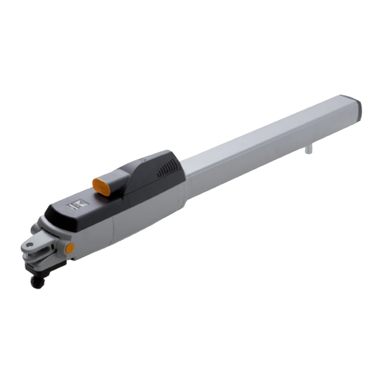
  • Seite 31 Schmierung (es ist wichtig, dass das obere und untere Scharnier lotrecht zueinander TECHNISCHE BESCHREIBUNG stehen) kontrollieren. 200/BL224E Der Antrieb ist zur Betätigung von Torflügeln (bis 2,2 m, 200 kg Gewicht pro • Den Kabelverlauf gemäß den Installationserfordernissen der Steuer- und Sicherheitsvor- Torflügel) geeignet und besteht aus einer kompakten und widerstandsfähigen Kombination richtungen gemäß...
  • Seite 32: Elektronischer Steuerung

    • Die Schneckenschraube des Antriebes (Teil 4, Abb. 2) bis auf 15 mm vor die Achtung! An keiner Stelle auf der Leiterplatte der Steuerung befindet vollständige Schließung drehen und die mechanischen Anschläge "7" und "9" sich die Stromspannung von 230 Vac: es ist allein nur die sehr niedrige (Abb.
  • Seite 33 Anschlussklemmleisten-Anschlüsse Anmerkung Der Jumper "J6" wählt den Typ der an Klemme 24 angeschlossenen CMN Neutralleitung für alle Eingänge/Ausgänge Sicherheitsleiste aus: - In Position 1 wird die Leiste mit NC-Kontakt ausgewählt; ELS Ausgang für Elektroschloss (ununterbrochen gesteuert) 12 Vdc – 15 W - In Position 2 wird die Sicherheitsleiste mit Kontakt 8.2 kΩ...
  • Seite 34: Programmierverfahren (Einstellungen Der Steuerung Und Des Strommess-Sensors)

    PROGRAMMIERVERFAHREN (Einstellungen der Steuerung und des Strommess-Sensors) • Das Vorhandensein der Öffnungs- und Schließungsanschläge ist für beide Torflügel obligatorisch. • Sich vergewissern, dass die Sicherheitsvorrichtungen sich in Ruhestellung befinden und dass die elektronische Leiterplatte mit Netzstrom versorgt wird; andernfalls ist der Eintritt in die Programmierung nicht möglich. •...
  • Seite 35: Menu Der Anzeige

    MENU DER ANZEIGE - Einstellung der Stromsensorstufe; Durch Betätigung der Taste PROG erfolgt der Zugriff zu den folgenden Funktionen: - Motorentypwahl; - Speicherung des Zustands der Dip-Schalter; - Einstellung der Schließfunktion bei einem Hindernis. - Anzeige des Zustands der Steuerungen und der Sicherheiten; - Einstellung der Motorleistung - Anzeige der Anzahl der Manöver;...
  • Seite 36 13-04-2001 Speicher vollkommen gelöscht werden. Falls die elektronische CARDIN ELETTRONICA S.p.A - 31020 San Vendemiano (TV) Italy - via Raffaello, 36 Tel: 0438/401818 Fax: 0438/401 eine Sekunde dauernden Bipton von sich und begeben sich in den "funkge- Karte im Falle eines Defekts ausgewechselt werden muss, kann das steuerten"...
  • Seite 37: Wartung

    4) Notfall-Betätigung • Bei blockiertem Tor werden zum Sparen des Batteriestromes die kontrollierten externen Stromverbraucher (CTRL 30 Vdc) nicht mit Strom versorgt. Wenn ein Wenn die elektronische Steuerung wegen eines Defektes nicht mehr auf die Befehl (über Kabelleitung oder Funk) gegeben wird, versorgt die Steuerung Befehlseingabe anspricht, sind die Eingänge EMRG1 oder EMRG2 zur manuellen zuerst die Stromverbraucher und bewertet den Zustand der Sicherheitsvor- Betätigung des Torflügels 1 zu verwenden.
  • Seite 38 Betriebsfunktionsmeldungen DISPLAY-ANZEIGEN (D1 - Seite 6) Anzeigen beim Anschalten Programmierung der Pausenzeit Anzeige für zwei Sekunden: "CC242C" = Steuereinheitsmodell Automatische Programmierung im Gange Signalisiert die Speicherung der Konfiguration der Dip-Schalters Zeigt bei der Programmierung an, dass das System sich und der Firmwareversion. auf die Betriebsweise mit einem einzelnen Torflügel eingestellt hat Alarmsignale...
  • Seite 39: Advertencias Para El Uso

    • Fijar el pilar (fig. 7, pág. 5) y el estribo de cola respetando las cotas "A" y "B" (fig. 4, • Alojamiento de la placa de bornes para el cableado con cable Cardin CABPC10 pág. 4), luego de haber controlado la posición de la bisagra de la cancilla respecto provisto de tapa de protección y pasacables incorporado.
  • Seite 40: Programador Electrónico

    • Extraer el cárter de protección del tornillo sinfin (todo el sistema tornillo sinfin, ¡Atención! En ningún punto de la tarjeta del programador está presente la tornillo patrón, tacos ajustables de seguridad resultará expuesto). tensión de 230 Vac: se dispone sólo de la muy baja tensión de seguridad. •...
  • Seite 41 Conexionado placa de bornes Nota El puente "J6" selecciona el tipo de banda sensible conectada con el borne 24: - en posición 1 se selecciona la banda sensible con contacto NC; CMN Común para todas las entradas/salidas - en posición 2 se selecciona la banda sensible de seguridad con contacto 8.2 kΩ; ELS salida para cerradura eléctrica (controlada en continuo) 12 Vdc–15W Si se puentea la entrada CSP, situar el puente "J6"...
  • Seite 42 PROCEDIMIENTO DE PROGRAMACIÓN (Fijación entradas programador y sensor de corriente) • Es obligatoria la presencia de los topes de apertura y cierre para las dos hojas. • Controlar que los dispositivos de seguridad se encuentren en la posición de reposo y que la tarjeta esté alimentada por la red eléctrica; en caso contrario, no se entrará...
  • Seite 43: Menú De Visualización

    MENÚ DE VISUALIZACIÓN Actuando sobre la tecla PROG, se accede -en secuencia- a las siguientes funciones: - configuración del nivel del sensor de corriente; - memorización del estado de los dip-switches; - selección del tipo de motor; - visualización del estado de los dispositivos de mando y seguridad; - configuración función de cierre con obstáculo;...
  • Seite 44: Modalidad De Funcionamiento

    13-04-2001 Draft : Indicaciones LED "L4" (pág. 6) CARDIN ELETTRONICA S.p.A - 31020 San Vendemiano (TV) Italy - via Raffaello, 36 Tel: 0438/401818 Fax: 0438/40183 Nota: Cuando la memoria estará totalmente ocupada, el avisador acústico emi- LED centelleante rápidamente: borrado de un código tirá...
  • Seite 45: Mantenimiento

    4) Maniobra de emergencia Resulta que la ejecución del mando, si está permitida (dispositivos de seguridad Si el programador electrónico no reaccionara a los controles por un mal fun- en reposo), será diferido por el tiempo necesario para el correcto funcionamiento cionamiento, actuar sobre las entradas EMRG1 o EMRG2 para mover la hoja de los dispositivos mismos (aproximadamente 1 segundo).
  • Seite 46 Señalizaciones de funcionamiento INDICACIONES EN EL DISPLAY (D1 - página 6) Visualizaciones tras el encendido Programación del tiempo de pausa Visualizado por dos segundos: "CC242C" = modelo de la centralita Programación automática en curso Señaliza la memorización de la configuración de los dip-switches y la versión del firmware.
  • Seite 47 Die CE-Konformitätserklärungen für die Cardin-Produkte stehen in der Originalsprache auf der Homepage www.cardin.it im Bereich "Normen und Zertifizierung" zur Verfügung. Las declaraciones de conformidad CE de los productos Cardin se encuentran disponibles en el idioma original en el sitio www.cardin.it en la sección "normas y certificaciones".
  • Seite 48: Caratteristiche Tecniche

    Frecuencia de recepción S449 433.92 Número de canales N° Número de funciones gobernables N° Número de códigos almacenables N° CARDIN ELETTRONICA spa Via del lavoro, 73 – Z.I. Cimavilla 31013 Codognè (TV) Italy Tel: +39/0438.404011 Fax: +39/0438.401831 email (Italian): Sales.office.it@cardin.it email (Europe): Sales.office@cardin.it...

Inhaltsverzeichnis