Herunterladen Inhalt Inhalt Diese Seite drucken
Trix BR 185.1 Bedienungsanleitung
Vorschau ausblenden Andere Handbücher für BR 185.1:

Werbung

Verfügbare Sprachen

Verfügbare Sprachen

D
GB
F
NL
USA
Modell der BR 185.1
21527

Werbung

Inhaltsverzeichnis
loading

Inhaltszusammenfassung für Trix BR 185.1

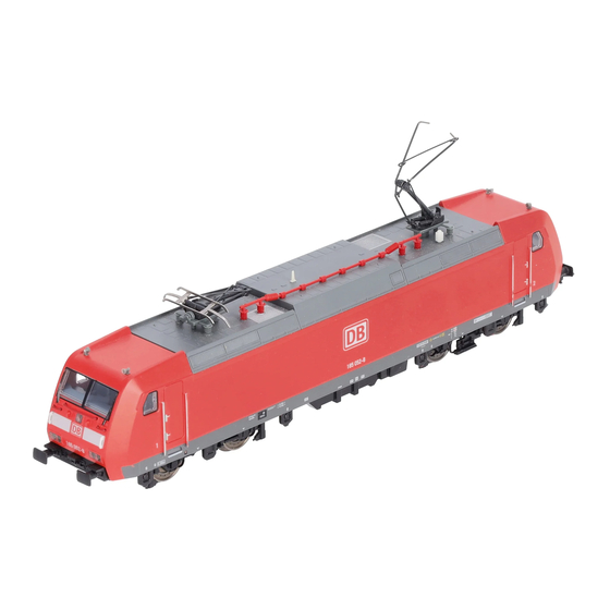
  • Seite 1 Modell der BR 185.1 21527...
  • Seite 3: Inhaltsverzeichnis

    Inhaltsverzeichnis: Seite Sommaire : Page Informationen zum Vorbild Informations concernant la locomotive réelle Sicherheitshinweise Remarques importantes sur la sécurité Wichtige Hinweise Information importante Multiprotokollbetrieb Mode multiprotocole Hinweise zum Digitalbetrieb Remarques relatives au fonctionnement en mode digital Schaltbare Funktionen Fonctions commutables Parameter/Register Paramètre/Registre Wartung und Instandhaltung...
  • Seite 4: Informationen Zum Vorbild

    Informationen zum Vorbild Information about the prototype 1994 erschien die AEG-Versuchslokomotive 12X, die fortan In 1994, the AEG experimental 12X locomotive appeared, als 128 001 bei der DB in Erprobung war. Die gewonnenen which then underwent testing as road no. 128 001 on the DB. Erkenntnisse flossen in die Entwicklung der Baureihe 145.
  • Seite 5 Informations concernant la locomotive réelle Informatie over het voorbeeld En 1994 apparut la locomotive d‘essai 12X d‘AEG, dès lors In 1994 verscheen de AEG-proeflocomotief 12X, die voortaan testée par la DB sous l‘immatriculation 128 001. Les résultats als 128 001 bij de DB op proef was. De opgedane ervaringen obtenus furent exploités pour la conception de la série 145.
  • Seite 6: Sicherheitshinweise

    Priorität 2: DCC werden. Priorität 3: DC • Für Reparaturen oder Ersatzteile wenden Sie sich bitte an Hinweis: Wenn zwei oder mehr digital-Protokolle am Ihren Trix-Fachhändler. Gleis erkannt werden, wählt der Decoder automatisch das • Gewährleistung und Garantie gemäß der beiliegenden höchstwertige Protokoll. Wird z.B. mfx und DCC erkannt, Garantieurkunde. wählt der Decoder mfx.
  • Seite 7: Hinweise Zum Digitalbetrieb

    Hinweis: Beachten Sie, dass nicht alle Funktionen in allen mfx-Protokoll Digital-Protokollen möglich sind. Unter mfx und DCC können Adressierung einige Einstellungen von Funktionen, welche im Analog- • Keine Adresse erforderlich, jeder Decoder erhält eine Betrieb wirksam sein sollen, vorgenommen werden. einmalige und eindeutige Kennung (UID). Hinweise zum Digitalbetrieb • Der Decoder meldet sich an einer Central Station oder • Die genaue Vorgehensweise zum Einstellen der diversen Mobile Station mit seiner UID automatisch an.
  • Seite 8: Programmierung

    DCC-Protokoll • Alle Funktionen können entsprechend dem Funktions- mapping geschaltet werden. Adressierung • Weitere Information, siehe CV-Tabelle DCC-Protokoll. • Mögliche Adressen: Kurze, lange und Traktionsadresse Es wird empfohlen, die Programmierungen grundsätzlich auf • Adressbereich: dem Programmiergleis vorzunehmen. 1 – 127 (kurze Adresse, Traktionsadresse) Logische Funktionen 1 – 10239 (lange Adresse) • Jede Adresse ist manuell programmierbar. Anfahr-/Bremsverzögerung • Kurze oder lange Adresse wird über die CVs ausgewählt. • Die Beschleunigungs- und Bremszeit können getrennt • Eine angewandte Traktionsadresse deaktiviert die von einander eingestellt werden.
  • Seite 9: Schaltbare Funktionen

    f0 f8 f0 - f3 f4 - f7 Schaltbare Funktionen STOP mobile station Spitzensignal Funktion f0 Funktion f0 ABV aus — Funktion 4 Funktion f4 Funktion f4 Spitzensignal Führerstand 2 aus — Funktion 6 Funktion f6 Funktion f6 Spitzensignal Führerstand 1 aus —...
  • Seite 10: Parameter/Register

    Bedeutung Wert DCC ab Werk Adresse 1 - 127 PoM Minimalgeschwindigkeit 0 - 255 PoM Anfahrverzögerung 0 - 255 PoM Bremsverzögerung 0 - 255 PoM Maximalgeschwindigkeit 0 - 255 Werkreset/Herstellerkennung PoM Funktionen F1 - F8 im Analogbetrieb 0 - 255 PoM Funktionen F9 - F15 und Licht im Analogbetrieb 0 - 255 Erweiterte Adresse (oberer Teil)
  • Seite 11: Safety Notes

    Note: If two or more digital protocols are recognized in the well as transferred along with the product to others. track, the decoder automatically takes on the highest value • Please see your authorized Trix dealer for repairs or digital protocol.For example, if mfx & DCC are recognized, spare parts.
  • Seite 12: Notes On Digital Operation

    Notes on digital operation mfx Protocol • The operating instructions for your central unit will give Addresses you exact procedures for setting the different parame- • No address is required; each decoder is given a one- ters. time, unique identifier (UID). • The values set at the factory have been selected for mfx • The decoder automatically registers itself on a Central in order to guarantee the best possible running characte- Station or a Mobile Station with its UID. ristics.
  • Seite 13 DCC Protocol • See the CV description for the DCC protocol for additional information. Addresses We recommend that in general programming should be • Possible addresses: short, long, and m.u. address done on the programming track. • Address range: Logic Functions 1 – 127 (short address, m.u. address) 1 – 10239 (long address) Acceleration / Braking Delay • Every address can be programmed manually.
  • Seite 14: Controllable Functions

    f0 f8 f0 - f3 f4 - f7 Controllable Functions STOP mobile station Headlights Function f0 Function f0 ABV off — Function 4 Function f4 Function f4 Headlights Engineer‘s Cab 2 off — Function 6 Function f6 Function f6 Headlights Engineer‘s Cab 1 off —...
  • Seite 15: Parameter/Register

    Discription DCC Value Factory-Set Address 1 - 127 PoM Minimum Speed 0 - 255 PoM Acceleration delay 0 - 255 PoM Braking delay 0 - 255 PoM Maximum speed 0 - 255 Factory Reset / Manufacturer Recognition PoM Functions F1 - F8 in analog operation 0 - 255 PoM Functions F9 - F15 and lights in analog operation 0 - 255...
  • Seite 16: Remarques Importantes Sur La Sécurité

    Remarques importantes sur la sécurité • L’intégralité des fonctions est disponible uniquement en exploitation Trix Systems, DCC et mfx. • La locomotive ne peut être utilisée qu‘avec le système • Feux de signalisation s‘inversant selon le sens de mar- d‘exploitation indiqué. che; feux commutables en exploitation digital. • Analogique max. 15 Volt =, digital max. 22 Volt ~. • Rayon minimal d’inscription en courbe 360 mm. • La locomotive ne peut pas être alimentée électriquement par plus d‘une source de courant à la fois.
  • Seite 17: Remarques Relatives Au Fonctionnement En Mode Digital

    Protocole mfx Indication : remarquez que toutes les fonctions ne peuvent pas être actionnées dans tous les protocoles numériques. Adressage Sous mfx et sous DCC, il est possible de procéder à • Aucune adresse n’est nécessaire, le décodeur reçoit tou- quelques paramétrages de fonctions devant être actives tefois une identification unique et non équivoque (UID).
  • Seite 18 Protocole DCC avec ceux de l’appareil de commande. • Toutes les fonctions peuvent être commutées en fonction Adressage du mappage des fonctions (voir le descriptif des CVs). • Adresse possibles: Courtes, longues et adresses de traction • Pour toute information complémentaire, voir le tableau • Catégorie d’adresse : des CVs, protocole DCC. 1 à 127 (adresses courtes, adresses de traction) Il est recommandé, de réaliser la programmation, fonda- 1 à...
  • Seite 19: Fonctions Commutables

    f0 f8 f0 - f3 f4 - f7 Fonctions commutables STOP mobile station Fanal éclairage activé Fonction f0 Fonction f0 ABV désactivé — Fonction 4 Fonction f4 Fonction f4 Fanal cabine de conduite 2 éteint — Fonction 6 Fonction f6 Fonction f6 Fanal cabine de conduite 1 éteint —...
  • Seite 20: Paramètre/Registre

    Affectation DCC Valeur Parm. Usine Adresse 1 - 127 PoM Vitesse minimale 0 - 255 PoM Temporisation d‘accélération 0 - 255 PoM Temporisation de freinage 0 - 255 PoM Vitesse maximale 0 - 255 Réinitialisation d’usine/identification du fabricant PoM Fonctions F1 - F8 en mode analogique 0 - 255 PoM Fonctions F9 - F15 et éclairage en mode analogique 0 - 255...
  • Seite 21: Veiligheidsvoorschriften

    Opmerking: let er op dat niet alle functies in alle digitaal- • De volledige toegang tot alle functies is alleen mogelijk protocollen mogelijk zijn. Onder mfx of DCC kunnen enkele met Trix Systems, DCC of met mfx bedrijf. instellingen, welke in analoogbedrijf werkzaam moeten zijn, • Ingebouwde, rijrichtingsafhankelijke frontverlichting is in ingesteld worden.
  • Seite 22: Aanwijzingen Voor Digitale Besturing

    Aanwijzingen voor digitale besturing mfx-protocol • Het op de juiste wijze instellen van de diverse parame- Adressering ters staat beschreven in de handleiding van uw digitale • Een adres is niet nodig, elke decoder heeft een éénmalig Centrale. en éénduidig kenmerk (UID). • Fabrieksmatig zijn de waarden voor mfx zo ingestelt dat • De decoder meldt zich vanzelf aan bij het Central Station optimale rijeigenschappen gegarandeerd zijn. of Mobile Station met zijn UID. Voor andere bedrijfssystemen moeten eventueel aanpas- • Naam af de fabriek: 185 070-0 singen uitgevoerd worden.
  • Seite 23 DCC-protocol • Alle functies kunnen overeenkomstig de functiemapping geschakeld worden (zie CV-beschrijving). Adressering • Voor verdere informatie, zie de CV-tabel DCC-protocol. • Mogelijke adressen: kort, lang en tractieadres Het is aan te bevelen om het programmeren alleen op het • Adresbereik: programmeerspoor uit te voeren. 1 – 127 (kort adres, tractieadres) 1 – 10239 (lange adres) Fysieke functies • Elk adres is handmatig programmeerbaar.
  • Seite 24: Schakelbare Functies

    f0 f8 f0 - f3 f4 - f7 Schakelbare functies STOP mobile station Frontverlichting Functie f0 Functie f0 ABV uit — Functie 4 Functie f4 Functie f4 Frontsein cabine 2 uit — Functie 6 Functie f6 Functie f6 Frontsein cabine 1 uit —...
  • Seite 25: Parameter/Register

    Betekenis Waarde DCC Af fabriek Adres 1 - 127 PoM Minimale snelheid 0 - 255 PoM Optrekvertraging 0 - 255 PoM Afremvertraging 0 - 255 PoM Maximumsnelheid 0 - 255 Fabrieksinstelling/fabriekherkenning PoM functies F1 - F8 in analoogbedrijf 0 - 255 PoM functies F9 - F15 en licht in analoogbedrijf 0 - 255 Uitgebreld adres (bovenste gedeelte)
  • Seite 31 1 Dachausrüstung E229 278 Hinweis: Einige Teile werden nur ohne oder mit anderer 2 Einarm-Stromabnehmer E610 677 Farbgebung angeboten. 3 Einarm-Stromabnehmer — Teile, die hier nicht aufgeführt sind, können nur im Rahmen 4 Trägerisolation E408 886 einer Reparatur im Märklin-Reparatur-Service repariert 5 Zylinderschraube E785 340 werden.
  • Seite 32 If you should want such certification to be done, please contact us – also due to the additional costs incurred for this. Gebr. Märklin & Cie. GmbH Stuttgarter Str. 55 - 57 73033 Göppingen 251931/0515/Ha1Ef Germany Änderungen vorbehalten www.maerklin.com/en/imprint.html www.trix.de © Gebr. Märklin & Cie. GmbH...

Inhaltsverzeichnis