Bresser MyTemp WTM Schnellstartanleitung
Inhaltsverzeichnis
Verfügbare Sprachen
Verfügbare Sprachen
Quicklinks
Inhaltsverzeichnis

Verwandte Anleitungen für Bresser MyTemp WTM


Inhaltszusammenfassung für Bresser MyTemp WTM
- Seite 1 Wetterstation · Weather Station · MyTemp WTM Schnellstartanleitung Quickstart guide...
- Seite 2 Entonces visite nuestra página web utilizando el siguiente enlace (código QR) para ver las versiones disponibles. Desidera ricevere informazioni esaustive su questo prodotto in una lingua specifica? Venga a visitare il nostro sito Web al seguente link (codice QR Code) per conoscere le versioni disponibili. www.bresser.de/download/7006200 GARANTIE · WARRANTy · GARANTíA · GARANzIA www.bresser.de/warranty_terms...
-
Seite 3: Gültigkeitshinweis
Hersteller-Anschrift gerichtete Anfra- gen oder Einsendungen nicht bearbeitet werden können. Irrtümer und technische Änderungen vorbehalten. © 2017 Bresser GmbH Alle Rechte vorbehalten. Die Reproduktion dieser Dokumentation – auch auszugs- weise – in irgendeiner Form (z.B. Fotokopie, Druck, etc.) so- wie die Verwendung und Verbreitung mittels elektronischer Systeme (z.B. -
Seite 4: Zu Dieser Anleitung
Anleitungsversion: v032017a Bezeichnung dieser Anleitung: Quickstart_7006200_My- Temp-WTM_de-en_BRESSER_v032017a Informationen bei Serviceanfragen stets angeben. 3 Zu dieser Anleitung HINWEIS Diese Schnellstart-Anleitung ersetzt nicht die ausführli- che Bedienungsanleitung! Lesen Sie vor Benutzung des Geräts aufmerksam die Si- cherheitshinweise und die ausführliche Bedienungsanlei- tung. 4 / 24... -
Seite 5: Teileübersicht Und Lieferumfang
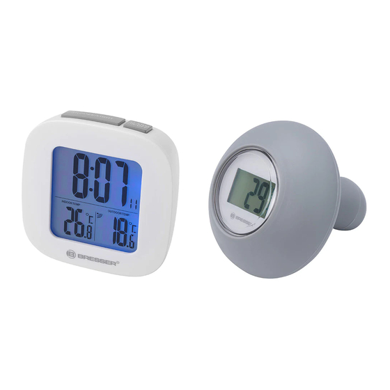
4 Teileübersicht und Lieferumfang Abb. 1: Teileübersicht für Basisstation (oben) und Funk- sensor (unten) Display (Basisstation) SNOOZE/LIGHT-Taste (Schlummerfunktion und temporäre Hintergrund- beleuchtung) ALARM-Taste (Weck- MODE-Taste (Zeitmo- rufeinstellung oder An- dus-Wahl) zeigenwahl) 5 / 24... - Seite 6 UP-Taste (Wertände- DOWN-Taste (Wertän- rung aufwärts) derung abwärts) MEM-Taste (Abruf ge- Batteriefach (Basisstati- speicherter Werte) Display (Funksensor) 10 Ansatzkante Silikonhülle 11 Batteriefach (Funksen- 12 Silikon-Dichtungsrah- sor) (unter Silikonhülle) 13 Thermosenor unten 14 Thermosensor oben Lieferumfang Basisgerät (A), Funksensor (B) Erforderliche Batterien (nicht im Lieferumfang enthalten): 2 Stck.
-
Seite 7: Display-Anzeigen
5 Display-Anzeigen Abb. 2: Display-Anzeigen für Basisstation (oben) und Funksensor (unten) Aktuelle Uhrzeit (Stun- Aktuelle Uhrzeit (Minu- den) ten) Alarmunterbrechung Alarm aktiv (stetige An- (Schlummern) aktiv zeige) Aktuelle Uhrzeit (Sekun- Wasser-/Außentempera- den) tur-Information Temperatureinheit (°C Gegenwärtige Wasser-/ oder °F wählbar) Außentemperaturwert Symbol für Datenemp- 10 Gegenwärtige Innentem- fang... - Seite 8 15 Weckzeitmodus-Infor- 16 Höchst- oder Tiefstwert mation (im Einstellm- für Wasser-/Außentem- odus) peratur (abhängig von 17 Höchst- oder Tiefstwert 18 Symbol Höchst- (MAX) für Innentemperatur (ab- oder Tiefsttemperatur hängig von 18) (MIN) 19 Datumsanzeige (Tag) 20 Datumsanzeige (Monat) 21 Gegenwärtige Wasser-/ 22 Temperatureinheit (°C) Außentemperatur 23 Komfort-Level-Indikator 24 Symbol für Datenüber-...
-
Seite 9: Stromversorgung Herstellen
erneut aufgebaut werden kann. Wird eines der beiden Ge- räte über einen Netzstromanschluss betrieben, so muss auch für dieses bei einem Batteriewechsel kurzzeitig die Stromverbindung getrennt werden. Werden z.B. nur die Bat- terien im Sensor ausgetauscht, kann das Signal anschlie- ßend gar nicht oder nicht mehr korrekt empfangen werden. -
Seite 10: Manuelle Zeiteinstellung
HINWEIS! Beim Abnehmen des Batteriefachdeckels darauf achten, dass der schmale Silikon-Dichtungs- rahmen nicht versehentlich verloren geht. Er dient als wichtiger Schutz vor eindringendem Wasser und haftet häufig am Batteriefachdeckel. Batterien in das Batteriefach einsetzen. Dabei die kor- rekte Ausrichtung der Batteriepole (+/-) beachten. Dichtungsrahmen auf den Rand des Batteriefachs auf- legen. -
Seite 11: Automatische Messwerteübertragung
9 Automatische Messwerteübertragung Sobald die Batterien eingelegt wurden, beginnt die Basis- station mit der Anzeige der Messwerte für den Innenbe- reich. Die ersten vom Außensensor empfangenen Messwer- te werden innerhalb von etwa 3 Minuten nach Inbetriebnah- me angezeigt. Nähere Informationen zum Abruf weiterer Messwerte sind der ausführlichen Bedienungsanleitung zu entnehmen (sie- he Download-Information auf Seite 2). -
Seite 12: Eg-Konformitätserklärung
Quecksilber und "Pb" steht für Blei. 11 EG-Konformitätserklärung Eine „Konformitätserklärung“ in Übereinstimmung mit den anwendbaren Richtlinien und entsprechenden Normen ist von der Bresser GmbH erstellt worden. Diese kann auf Anfrage jederzeit eingesehen werden. 12 Garantie Die reguläre Garantiezeit beträgt 2 Jahre und beginnt am Tag des Kaufs. - Seite 24 Teléfono*: +34 91 67972 69 Telephone*: +44 1342 837 098 BRESSER Iberia SLU BRESSER UK Ltd c/Valdemorillo,1 Nave B Unit 1 starborough Farm, P.I. Ventorro del cano Starborough Road, Nr Marsh Green, 28925 Alcorcón Madrid Edenbridge, Kent TN8 5RB España...