HEIDENHAIN LIF 17 R Montageanleitung
Inhaltsverzeichnis
Quicklinks
For scale mounting, please refer to the separate Instructions.
Für Montage des Maßstabes bitte separate Anleitung beachten.
Pour le montage de la règle, veuillez vous reporter au manuel dédié.
Per il montaggio del nastro graduato fare riferimento al relativo manuale.
Tener en cuenta las instrucciones suministradas por separado para el montaje de la regla.
Mounting Instructions
Montageanleitung
Instructions de montage
Istruzioni di montaggio
Instrucciones de montaje
LIF 17 R
LIF 18 R
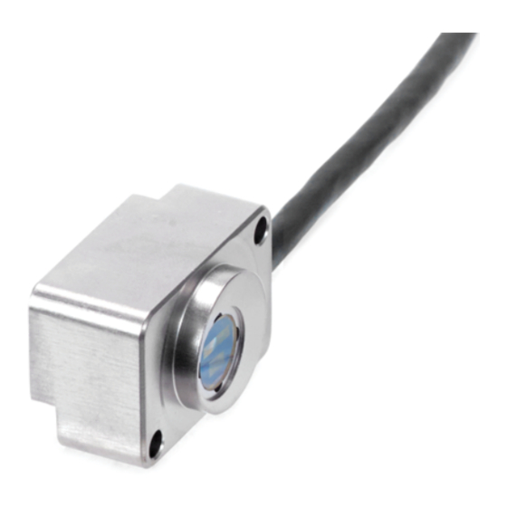
Scanning head
Abtastkopf
Tête captrice
Testina di scansione
Cabezal captador
03/2018
Inhaltsverzeichnis

Verwandte Anleitungen für HEIDENHAIN LIF 17 R


Inhaltszusammenfassung für HEIDENHAIN LIF 17 R
- Seite 1 Mounting Instructions Montageanleitung Instructions de montage Istruzioni di montaggio Instrucciones de montaje LIF 17 R LIF 18 R Scanning head For scale mounting, please refer to the separate Instructions. Abtastkopf Für Montage des Maßstabes bitte separate Anleitung beachten. Tête captrice Pour le montage de la règle, veuillez vous reporter au manuel dédié.
- Seite 2 Contents Page Seite Warnings Warnhinweise Inhalt Sommaire Items Supplied Lieferumfang Indice Mounting Procedure Hinweise zur Montage Mounting Montage Indice Adjustment Justage 13 Adjusting the position of the reference mark 13 Justage der Referenzmarkenlage 14 Adjusting the central reference mark R 14 Mittige Referenzmarke R justieren 18 Checking the Status Display 18 Funktionsanzeige überprüfen...
-
Seite 3: Warnhinweise
Warnings Warnhinweise Avertissements Avvertenze Advertencias Note: Mounting and commissioning is to be conducted by a qualified specialist under compliance with local safety regulations. Do not engage or disengage any connections while under power. The system must be disconnected from power. Achtung: Die Montage und Inbetriebnahme ist von einer qualifizierten Fachkraft unter Beachtung der örtlichen Sicherheitsvorschriften vorzunehmen. - Seite 4 Standard di formitura Suministro LIF 17 R/LIF 18 R scanning head, spacer shim Abtastkopf LIF 17 R/LIF 18 R, Abstandsfolie Mounting Instructions Tête captrice LIF 17 R/LIF 18 R, feuille de réglage Montageanleitung Instructions de montage Istruzioni di montaggio Instrucciones de montaje...
-
Seite 5: Mounting Procedure
Mounting Procedure Hinweise zur Montage Procédure de montage Avvertenze per il montaggio Indicaciones para el montaje The protective film of the linear scale must be removed. If there is any contamination, clean the graduation of the scale tape and the scanning head with a lint-free cloth and isopropyl alcohol. - Seite 6 Minimum distance from sources of interference. Mindestabstand von Störquellen. Distance minimale des sources de perturbation. Distanza minima da sorgenti di disturbo. Distancia mínima respecto a las fuentes de interferencias. Mounting tolerances 1 = Mounting clearance Anbautoleranzen 1 = Montageabstand Tolérances de montage 1 = Distance de montage Tolleranze di montaggio 1 = Distanza di montaggio...
- Seite 7 Mounting Montage Montage Montaggio Montaje LIF 101C Ensure correct position of the scale to the scanning head! LIF 101C Set the mounting clearance to 0.5 mm with the spacer shim. Tighten the scanning head just enough to allow adjustment. Auf die richtige Lage von Maßstab zu Abtastkopf achten! Mit Abstandsfolie 0,5 mm Montageabstand einstellen.
- Seite 8 Permissible bending radii of connecting cable. R1: for rigid configuration, R2: for frequent flexing Zulässige Biegeradien der Anschlusskabel. R1: Dauerbiegung, R2: Wechselbiegung Rayons de courbure admissibles sur le câble de raccordement. R1 : Courbure permanente, R2 : Courbure fréquente Raggio di curvatura consentito per il cavo di collegamento: R1: con curvatura fissa, R2: con flessioni ripetute Radios de torsión admisibles en los cables.
-
Seite 9: Adjustment
Adjustment Justage Réglage Taratura Ajuste Perform the adjustment using the PWT 100 encoder diagnostic set. Please refer to the PWT 100 operating/installation instructions (included on CD), chapter “Diagnostics of the measuring devices. ” As an alternative, a PWM 20/PWM 21/PWM 9 encoder diagnostic set can be used. Justage mit Messgerät-Diagnoseset PWT 100 durchführen. - Seite 10 Do not connect while powered! Steckverbindung nicht unter Spannung durchführen! Ne procéder à aucun branchement sous tension ! Non eseguire i collegamenti sotto tensione! ¡No efectuar las conexiones de enchufe bajo tensión! PWT 100 In the main menu of the PWT 100, select “Automatic Diagnosis” Im Hauptmenü...
- Seite 11 Important: in the PWT display via More Functions: Deactivate the evaluation of incremental signals (HSP active)! ( Back) The PWT display view makes it possible to use moving-bar graphics for the evaluation of incremental signals and reference mark signals. Wichtig: in der PWT-Anzeige über More ...
- Seite 12 The black bar represents the current signal amplitude of the incremental signals. The farther the black bar moves to the right, the greater the signal amplitude is. Der schwarze Balken zeigt die aktuelle Signalamplitude der Inkrementalsignale an. Je weiter der schwarze Balken nach rechts wandert, umso größer ist die Signalamplitude.
- Seite 13 Adjusting the position of the reference mark Justage der Referenzmarkenlage Réglage de la position de la marque de référence Taratura della posizione dell’indice di riferimento Ajuste de la posición de la marca de referencia LIF 1x1R LIF 1x1C Traverse the reference mark with the scanning head.
- Seite 14 Adjusting the central reference mark R Justage der mittigen Referenzmarke R Réglage de la marque de référence centrale R Taratura dell’indice di riferimento centrale R Ajuste de la marca de referencia central R Green = good Optimum Grün = gut, Optimal Vert = bien Optimal...
- Seite 15 LIF 1x1 C v = max. 0.4 m/s To check the reference marks, traverse the entire measuring length. Recommendation: Tap „Refresh“ in the display to reset the drag indicators Zur Prüfung der Referenzmarken über die gesamte Messlänge verfahren. Empfehlung: mit „Refresh“ im Display können die Schleppzeiger zurückgestellt werden. Pour vérifier les marques de référence, parcourir toute la longueur de mesure.
-
Seite 16: Bei Abweichung
LIF 1x1 C If there is a deviation: Select the reference mark whose position is centered in the area of the two drag indicators (min./max.) and adjust it to the optimum setting. Bei Abweichung: Referenzmarke auswählen deren Lage mittig im Bereich der beiden Schleppzeiger (min./max.) liegt und diese auf Optimal justieren. En cas d’écart : Sélectionner la marque de référence qui se trouve au centre des deux curseurs de poursuite (min./max.) et la régler sur Optimal. - Seite 17 LIF 1x1 C To check the reference marks, traverse zero crossovers over the entire measuring length. Zur Prüfung der Referenzmarken Nulldurchgänge über die gesamte Messlänge verfahren. Pour vérifier les marques de référence, franchir les passages à zéro sur toute la longueur de mesure. Per verificare gli indici di riferimento, superare i punti di zero sull’intera corsa utile.
- Seite 18 Checking the Status Display Status Display Funktionsanzeige überprüfen Funktionsanzeige Contrôle du témoin LED Affi chage fonctionnel Verifica della funzionalità Visualizzazione della funzionalità Comprobar el indicador de función Indicador de función The integrated status display permits both a qualified judgment of the incremental signals as well as a check of the reference mark signal. If, after adjustment, the LED does not stay constantly green, or when the reference mark is scanned it turns briefly blue, check the installation tolerances and repeat the adjustment.
- Seite 20 DR. JOHANNES HEIDENHAIN GmbH Dr.-Johannes-Heidenhain-Straße 5 83301 Traunreut, Germany { +49 8669 31-0 | +49 8669 32-5061 E-mail: info@heidenhain.de Technical support | +49 8669 32-1000 Measuring systems { +49 8669 31-3104 E-mail: service.ms-support@heidenhain.de NC support { +49 8669 31-3101 E-mail: service.nc-support@heidenhain.de...