MAC Audio MAC 420 Installationsanleitung
Inhaltsverzeichnis
Verfügbare Sprachen
Verfügbare Sprachen
Quicklinks
Inhaltsverzeichnis

Verwandte Anleitungen für MAC Audio MAC 420


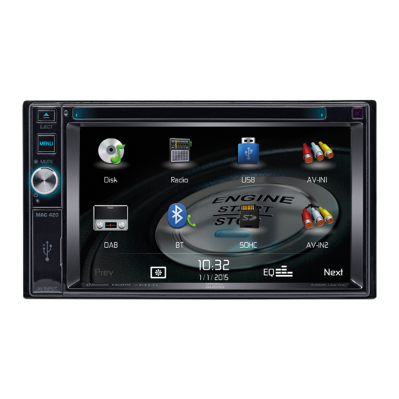
Inhaltszusammenfassung für MAC Audio MAC 420
- Seite 2 Anschlussdiagramm/ Wiring Diagram...
-
Seite 3: Benötigte Werkzeuge Und Materialien
Lieferumfang Benötigte Werkzeuge und Materialien: • MAC 420 Receiver • Torx-, Schlitz- und Kreuz-Schraubendreher • 2-DIN-Montageklammern fur linke und rechte Seite • Seitenschneider und Abisolierzange • 2-DIN-Montagerahmen • Werkzeug zum Herausnehmen des eingebauten • Zierblende Radios (Schraubendreher, Steckschlüsselsatz oder • Beutel mit Zubehör andere Werkzeuge) • ISO-Adapterkabel fur Stromversorgung/Lautsprecher • Isolierband • A/V Kabelbaum • Crimpzange • Externes Mikrofon • Spannungsmesser/Stromprüfer • Fernbedienung • Crimpverbindungen • Bedienungsanleitung • 18-adriges Anschlusskabel • Installationsanleitung • 16- bis 18-adriges Lautsprecherkabel... -
Seite 4: Verwendung Der Zierblende
3. Halten Sie das Radio vor die Öffnung im Armaturenbrett, sodass die Verkabelung durch das Armaturenbrett geführt werden kann. Beachten Sie das Schaltbild und stellen Sie sicher, dass alle Verbindungen mithilfe von Kabelsicherungen oder Isolierband geschutzt und isoliert sind. Wenn die Verkabelung abgeschlossen ist, verbinden Sie die ISO-Steckverbinder mit den entsprechenden Anschlussen auf der Ruckseite des Gehäuses. Schalten Sie das Gerät ein, um die Funktion zu prufen (die Zundung des Fahrzeugs muss eingeschaltet sein). Kann das Gerät nicht eingeschaltet werden, überprüfen Sie die Verkabelung, bis Sie den Fehler gefunden haben. 4. Montieren Sie das neue Radio im Armaturenbrett oder in der Mittelkonsole, indem Sie die in Schritt 1 beschriebenen Arbeiten in umgekehrter Reihenfolge ausfuhren. ACHTUNG! Achten Sie darauf, dass die Fahrzeugverkabelung nicht beschädigt wird. HINWEIS: Der Endbenutzer ist dafür verantwortlich, die Montage und den Betrieb des Geräts entsprechend den Gesetzen der Region und des Landes sicherzustellen. Das Kabel der HANDBREMSE muss wie in der Bedienungsanleitung angegeben angeschlossen werden. ACHTUNG: Die Lüftungsschlitze dürfen nicht verdeckt werden, da das Gerät ansonsten überhitzen und so beschädigt werden kann. Verwendung der Zierblende Im Lieferumfang ist eine Zierblende enthalten, um die Montagefexibilität zu erhöhen. Der Receiver passt in das Armaturenbrett der meisten Importfahrzeuge, ohne das Armaturenbrett bzw. den Einbauschacht zu verändern. Das Armaturenbrett mancher Fahrzeuge fur den US-amerikanischen Markt ist fur ein DIN-Doppelgehäuse geeignet, jedoch bleibt nach dem Einbau zwischen dem Radio unddem Armaturenbrett ein kleiner Spalt. Verwenden Sie in diesem Fall die passende Zierblende, um einen möglichen Spalt zu verdecken.