Seite 1
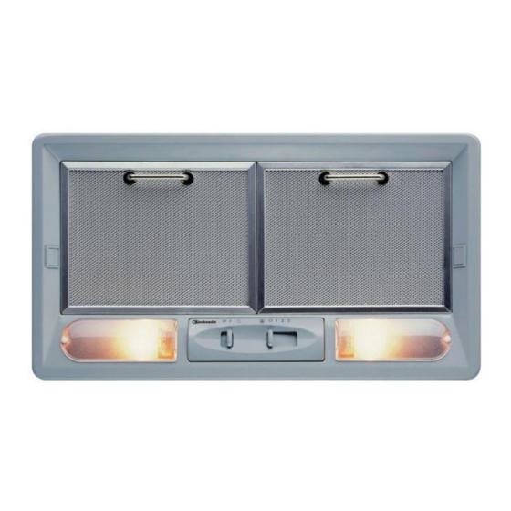
INSTRUCTIONS FOR USE AKR601UMIX (60cm) AKR801UMIX (80cm) Concealed Undermount Rangehood Let our 100 years of experience do the thinking for you...
WARNING! Accessible parts of the hood may become hot when used with cooking appliance. INSTALLATION SPECIFICATIONS: Use only the fixing screws supplied with the product for installation. Use the correct length screws which are identified in the Installation guide. WARNING! Failure to install the screw or fixing device in accordance with these instructions may result in electrical hazards.
Seite 4
INSTALLATION - MONTAGEANLEITUNG Der Mindestabstand zwischen dem Kochfeld und der unteren Kante der Dunstabzugshaube MUSS bei Elektroplatten 60 cm und bei Gas- oder kombinierten Herden 70 cm betragen. Überprüfen Sie vor der Installation auch die im Handbuch des Kochfeldes angegebenen Abstände. Die Installation der Abzugshaube muss von einer Fachkraft ausgeführt werden.
Seite 5
Entriegelung Ansaugoberfläche Bei einigen Modellen: 292 - 515 Höhen proportional zur Größe der Abzugshaube. Bei einigen Modellen: Ziehen Sie die Schrauben der Befestigungsfedern am Hängeschrank fest an. Befestigen Sie sie mit den mitgelieferten Schrauben. Benutzen Sie zum Einhaken des Gitters die Vorrichtungen L oder N.
INFORMATIONEN ZUM 11. Der Hersteller haftet nicht bei unsachgemäßem Gebrauch oder fehlerhafter Bedienung. UMWELTSCHUTZ 12. Das Gerät darf von Personen (einschließlich Kindern), deren 1. Verpackung physische, sensorische oder geistige Fähigkeiten oder Das Verpackungsmaterial ist zu 100 % wieder verwertbar und unzureichende Erfahrung und Kenntnisse einen sicheren durch das Recyclingsymbol gekennzeichnet.
Elektrischer Anschluss KUNDENDIENST Die Netzspannung muss mit der auf dem Typenschild im Bevor Sie den Kundendienst rufen Innenteil der Abzugshaube übereinstimmen. Falls die 1. Prüfen Sie erst, ob Sie die Störung selbst beheben können Abzugshaube mit einem Stecker versehen ist, schließen Sie sie an (siehe “Störung - Was tun?”).
Seite 8
PRODUKTANGABEN BEDIENFELD 4. Für den Ausbau drehen Sie den Filter oder den Griff gegen den Uhrzeigersinn. A. Lichtschalter 5. Bauen Sie das Gitter, den Filter oder den Fettfilter- B. Geschwindigkeits-Wahlschalter Halterungsrahmen wieder ein. Der Kohlefilter muss alle vier Monate gewechselt werden. AUSWECHSELN DER GLÜHLAMPEN: 1.
Seite 9
INSTALLATION - ASSEMBLY INSTRUCTIONS Note on installation and use: The minimum distance between the support surface of the recipients on the cooking device and the lowest part of the hood MUST NOT BE less than 60 cm in the case of electric cookers and 70 cm for gas or combination cookers.
Seite 10
Extractor surface release For selected models: 292 - 515 Measurements in proportion to hood size For selected models: tighten the screws of the fixing clips to the wall unit Secure using the screws provided To fit the grill, use components L or N Present on some models 5019 318 33288...
SAFEGUARDING THE ENVIRONMENT 12. The appliance is not intended for use by children or persons with limited physical, sensory or mental abilities or without 1. Packing experience and knowledge of it, unless they are under the Packing materials are 100% recyclable and are marked with the supervision of or instructed in its use by a person responsible recycling symbol .Comply with the local regulations for...
Electrical connection AFTER-SALES SERVICE Before calling the After-Sales Service The mains voltage must match that given on the rating plate 1. Check to see if you can fix the problem yourself (see located inside the hood. If provided with a plug, connect the “Troubleshooting Guide”).
Seite 13
PRODUCT SHEET CONTROL PANEL A. Light switch. B. Speed selector switch. REPLACING BULBS: 1. Disconnect power. Fig. 1 WARNING: Wear gloves. 2. Remove the grease filter support grille (Fig. 2) or the grease filter to access the lamp housing (Fig. 1). On some models the lamp cover can simply be prised off using standard screwdriver (A - Fig.
Seite 14
INSTALLATION - INSTRUCTIONS DE MONTAGE Remarque pour le montage : La distance minimum entre la surface de support des récipients sur le dispositif de cuisson et la partie la plus basse de la hotte NE DOIT PAS ÊTRE inférieure à 60 cm pour les cuisinières électriques et à...
Seite 15
Décrochage de la surface aspirante Pour certains modèles : 292 - 515 Cotes proportionnelles aux dimensions de la hotte Pour certains modèles : serrez les vis des ressorts de fixation sur l'élément mural Fixer avec les vis fournies Pour accrocher la grille, agissez sur les dipositifs L ou N Présent sur certains modèles 5019 318 33288...
CONSEILS POUR LA PROTECTION DE 11. Le fabricant décline toute responsabilité en cas de dommages résultant d’une utilisation impropre ou d’un L’ENVIRONNEMENT réglage erroné des commandes. 1. Emballage 12. Les personnes (y compris les enfants) qui, en raison de leurs Les matériaux d’emballage sont 100% recyclables et portent le capacités physiques, sensorielles ou mentales, de leur symbole du recyclage...
Branchement électrique SERVICE APRÈS-VENTE La tension de réseau doit correspondre à celle indiquée sur Avant d’appeler le Service Après-vente l’étiquette des caractéristiques située à l’intérieur de la hotte. Si 1. Vérifiez si vous ne pouvez pas éliminer le problème par la hotte est pourvue de fiche, branchez-la à...
FICHE PRODUIT LE BANDEAU DE COMMANDES 4. Pour retirer le filtre, faites-le tourner ou tournez la manette dans le sens inverse des aiguilles d'une montre. A. Interrupteur d'éclairage. 5. Remontez la grille, le filtre ou le cadre de support des filtres à B.
Seite 19
INSTALLATIE - MONTAGE-INSTRUCTIES Opmerking bij de installatie: De minimale afstand tussen het steunoppervlak van de pannen op het kooktoestel en het laagste deel van de afzuigkap MAG NIET minder dan 60 cm zijn bij elektrische kooktoestellen en 70 cm bij kooktoestellen op gas of gemengd. Controleer bovendien de afstanden die in de handleiding van de kookplaat zijn vermeld, voordat u de kap installeert.
Seite 20
Haak aanzuigoppervlak Bij sommige modellen: 292 - 515 Hoogtes evenredig aan de afmetingen van de kap Bij sommige modellen: Draai de schroeven van de bevestigingsveren aan het keukenkastje vast Bevestigen met de bijgeleverde schroeven Om het rooster vast te haken de voorzieningen L of N gebruiken Aanwezig bij sommige modellen...
MILIEUTIPS 11. De fabrikant aanvaardt geen enkele verantwoordelijkheid voor oneigenlijk gebruik van het apparaat of verkeerde 1. Verpakking instellingen van de bedieningselementen. Het verpakkingsmateriaal is voor 100% recyclebaar, hetgeen 12. Het gebruik van het apparaat is niet toegestaan aan personen wordt aangegeven met het symbool voor recycling .
Elektrische aansluiting KLANTENSERVICE De netspanning moet overeenstemmen met de spanning die op Alvorens de klantenservice in te schakelen het typeplaatje in de afzuigkap is vermeld. Indien de kap is 1. Ga na of u het probleem zelf kunt oplossen (zie “Opsporen voorzien van een stekker, dan moet deze worden aangesloten op van storingen”).
Seite 23
PRODUCTINFORMATIEBLAD HET BEDIENINGSPANEEL Rond filter: Plaats het koolstoffilter boven het beschermrooster van de motor, bij sommige modellen moet het referentiepunt B A. Lichtschakelaar. samenvallen met de pijl C op het afvoerkanaal; tenslotte B. Schakelaar voor het instellen van de snelheid. rechtsom draaien.
Seite 24
INSTALACIÓN - INSTRUCCIONES DE MONTAJE Nota para la instalación: La distancia mínima entre la superficie de apoyo de los recipientes en la placa de cocción y la parte más baja de la campana NO DEBE SER inferior a 60 cm en caso de cocinas eléctricas y 70 cm en caso de cocinas a gas o mixtas.
Seite 25
Desenganche de la superficie aspirante En algunos modelos: 292 - 515 Cotas proporcionales a las dimensiones de la campana En algunos modelos: Apretar los tornillos de los muelles de fijación al mueble colgante Fijar con los tornillos suministrados Para enganchar la rejilla actúe en los dispositivos L o N Presente en algunos modelos 5019 318 33288...
CONSEJOS PARA PRESERVAR EL MEDIO 11. El fabricante declinará toda responsabilidad por usos inapropiados o por errónea programación de los mandos. AMBIENTE 12. El uso del aparato no está permitido a personas (incluidos 1. Embalaje niños) con reducidas capacidades físicas, sensoriales o El material de embalaje se puede reciclar al 100% y está...
Conexión eléctrica SERVICIO DE ASISTENCIA TÉCNICA La tensión de red tiene que coincidir con la tensión indicada en la Antes de llamar al Servicio de Asistencia Técnica etiqueta de las características colocada en el interior de la 1. Compruebe si le es posible eliminar autónomamente el campana.
FICHA DEL PRODUCTO PANEL DE MANDOS A. Interruptor de la luz B. Interruptor de selección de la velocidad SUSTITUCIÓN DE LAS BOMBILLAS: Desconecte la campana de la red eléctrica Fig. 1 ADVERTENCIA: Use guantes de protección. 2. Quite la rejilla de soporte del filtro antigrasa (Fig. 2) o el filtro antigrasa para acceder al hueco de las bombillas (Fig.
Seite 29
INSTALAÇÃO - INSTRUÇÕES DE MONTAGEM Nota de instalação: A distância mínima entre a superfície de suporte dos recipientes no dispositivo de cozedura e a parte mais baixa do exaustor do fogão DEVE SER SUPERIOR a 60 cm no caso de fogões eléctricos e de 70 cm no caso de fogões a gás ou mistos.
Seite 30
Desencaixe da superfície de aspiração Para alguns modelos: 292 - 515 Quotas proporcionais à dimensão do exaustor Para alguns modelos: Aperte os parafusos das molas de fixação no móvel Fixe com os parafusos fornecidos Para encaixar a grelha intervenha nos dipositivos L ou N Presente em alguns modelos 5019 318 33288...
CONSELHOS PARA A PROTECÇÃO DO 11. O fabricante declina qualquer responsabilidade pela utilização incorrecta ou pela configuração incorrecta dos AMBIENTE comandos. 1. Embalagem 12. O aparelho não se destina a ser utilizado por pessoas A embalagem é constituída por material 100% reciclável e está (incluindo crianças) com capacidades físicas, sensoriais ou marcada com o símbolo de reciclagem .
Ligação eléctrica SERVIÇO PÓS-VENDA A tensão de rede deve corresponder à tensão indicada na Antes de contactar o Serviço de Assistência Técnica etiqueta de características situada no interior do exaustor. Se o 1. Verificar se não é possível eliminar sozinho as avarias exaustor estiver equipado com uma ficha, ligá-lo a uma tomada (consultar “Resolução de problemas”).
Seite 33
FICHA TÉCNICA DO PRODUTO O PAINEL DE CONTROLO 4. Para retirar o filtro, rode o filtro ou o manípulo no sentido contrário ao dos ponteiros do relógio. A. Interruptor da luz. 5. Monte novamente a grelha, o filtro ou o caixilho de suporte dos B.
Seite 34
INSTALLAZIONE - ISTRUZIONI DI MONTAGGIO Nota di installazione: La distanza minima fra la superficie di supporto dei recipienti sul dispositivo di cottura e la parte più bassa della cappa da cucina NON DEVE ESSERE inferiore a 60 cm in caso di cucine elettriche e a 70 cm in caso di cucine a gas o miste.
Seite 35
Sgancio superficie aspirante Per alcuni modelli: 292 - 515 Quote proporzionali alle dimensione della cappa Per alcuni modelli: Serrare le viti delle molle di fissaggio al pensile Fissare con le viti a corredo Per agganciare la griglia agire sui dipositivi L o N Presente in alcuni modelli 5019 318 33288...
CONSIGLI PER LA SALVAGUARDIA 12. L’utilizzo dell’apparecchio non è consentito alle persone (inclusi i bambini) con ridotte capacità fisiche, sensoriali o DELL’AMBIENTE mentali, o con mancanza di esperienza o conoscenza, a 1. Imballo meno che non abbiano avuto istruzioni riguardanti l’uso Il materiale di imballo è...
Collegamento elettrico SERVIZIO ASSISTENZA TECNICA La tensione di rete deve corrispondere alla tensione riportata Prima di contattare il Servizio Assistenza sull’etichetta caratteristiche situata all’interno della cappa. 1. Verificare se non è possibile eliminare da soli gli Se provvista di spina collegare la cappa ad una presa conforme inconvenienti (vedere “Guida ricerca guasti”).
SCHEDA PRODOTTO PANNELLO COMANDI coincidere con la freccia C stampata nel convogliatore; infine girare in senso orario. A. Interruttore luce. 4. Per togliere il filtro girare il filtro o la manopola in senso B. Interruttore selezione velocità. antiorario. 5. Rimontare la, griglia, il filtro o la cornice supporto filtri antigrasso.
Seite 39
ΕΓΚΑΤΑΣΤΑΣΗ - ΟΔΗΓΙΕΣ ΤΟΠΟΘΕΤΗΣΗΣ Σημείωση για την εγκατάσταση: Η ελάχιστη απόσταση ανάμεσα στην επιφάνεια στήριξης των σκευών στη συσκευή μαγειρέματος και στο χαμηλότερο σημείο του απορροφητήρα ΔΕΝ ΠΡΕΠΕΙ ΝΑ ΕΙΝΑΙ μικρότερη από 60 cm σε περίπτωση ηλεκτρικών εστιών και από 70 cm σε κουζίνες αερίου ή μικτές. Επίσης, πριν από την...
Seite 40
Απελευθέρωση επιφάνειας αναρρόφησης Για ορισμένα μοντέλα: 292 - 515 Αποστάσεις ανάλογες με τις διαστάσεις του απορροφητήρα Για ορισμένα μοντέλα: σφίξτε τις βίδες των ελατηρίων στερέωσης στο ντουλάπι Στερεώστε με τις διατιθέμενες βίδες Για να στερεώσετε τη γρίλια πιέστε στα σημεία L ή N Μόνο...
Seite 41
ΣΥΜΒΟΥΛΕΣ ΓΙΑ ΤΗΝ ΠΡΟΣΤΑΣΙΑ ΤΟΥ 10. Τα κανάλια εξαερισμού πρέπει να καταλήγουν πάντα σε εξωτερικό χώρο. ΠΕΡΙΒΑΛΛΟΝΤΟΣ 11. Ο κατασκευαστής δεν φέρει καμία ευθύνη για 1. Συσκευασία ακατάλληλες χρήσεις ή εσφαλμένες ρυθμίσεις των Τα υλικά της συσκευασίας είναι 100% ανακυκλώσιμα και διακοπτών.
Ηλεκτρική σύνδεση ΣΕΡΒΙΣ Η τάση του δικτύου πρέπει να αντιστοιχεί στην τάση που Πριν καλέσετε το Σέρβις αναγράφεται στην πινακίδα χαρακτηριστικών, στο 1. Βεβαιωθείτε ότι δεν μπορείτε να λύσετε το πρόβλημα εσωτερικό του απορροφητήρα. Εάν ο απορροφητήρας μόνοι σας (βλέπε “Οδηγός εντοπισμού βλαβών”). διαθέτει...
Seite 43
ΚΑΡΤΕΛΑ ΠΡΟΪΟΝΤΟΣ Ο ΠΙΝΑΚΑΣ ΧΕΙΡΙΣΜΟΥ Κυκλικό φίλτρο: Τοποθετήστε το φίλτρο ενεργού άνθρακα πάνω από τη γρίλια προστασίας του μοτέρ. Σε ορισμένα A. Διακόπτης φωτισμού. μοντέλα η ένδειξη B πρέπει να συμπίπτει με το βέλος C B. Διακόπτης επιλογής ταχύτητας. που είναι τυπωμένο στο συλλέκτη Τέλος γυρίστε δεξιόστροφα.