Herunterladen Inhalt Inhalt Diese Seite drucken
Inhaltsverzeichnis

Werbung

Verfügbare Sprachen

Verfügbare Sprachen

Bedienungs- und Wartungsanleitung
Notice d'utilisation et d'entretien
Istruzioni d'uso e manutenzione
Operating and maintenance instructions
JRG CleanLine Filter
Rückspülautomat
Dispositif de rinçage à
contre-courant
Dispositivo per il lavaggio
automatico in controcorrente I
Automatic backwash unit
1371.025/.032
1871.025/.032
8171.300
D
2 – 16
F
17 – 32
33 – 48
E
49 – 64

Werbung

Inhaltsverzeichnis
loading

Inhaltszusammenfassung für JRG CleanLine Filter

  • Seite 1 Bedienungs- und Wartungsanleitung Notice d’utilisation et d’entretien Istruzioni d’uso e manutenzione Operating and maintenance instructions JRG CleanLine Filter Rückspülautomat 2 – 16 Dispositif de rinçage à contre-courant 17 – 32 Dispositivo per il lavaggio automatico in controcorrente I 33 – 48 Automatic backwash unit 49 –...
  • Seite 2: Inhaltsverzeichnis

    1. Hinweise 1.1. Sicherheitssymbole 1.2. Verwendung/Funktion 1.3. Fachpersonal 1.4. Gefahr durch elektrische Energie 1.5. Gefahr durch drehenden Ablaufstutzen 1.6. Verpackung/Transport Konformität/EG Einbauerklärung 2. Aufbau/Technische Daten 2.1. Aufbau 2.2. Technische Daten Netzteil 2.3. Technische Daten Rückspülautomat 3. Einbauort/Installation 4. Inbetriebnahme 5. Einstellmöglichkeiten 5.1.
  • Seite 3: Hinweise

    Line Combi/Filter Nr. 35 09 458 73 und die Be- dienungs- und Wartungsanleitung JRG Clean- Warnung Line Filter Nr. 35 09 458 71 bzw. JRG CleanLine Dieses Symbol weist auf eine Information Combi Nr. 35 09 458 72 zu beachten.
  • Seite 4: Verwendung/Funktion

    1.2. Verwendung/Funktion Die Firma Georg Fischer JRG AG übernimmt für Der elektrische Rückspülautomat zu der Arma- unsachgemässe Installationen keine Haftung. tur JRG CleanLine (Combi/Filter) dient zur auto- Spannungsspitze matischen Rückspülung des Feinfiltereinsatzes. Die Rückspülung kann individuell (Häufigkeit, Spannungsspitzen, welche die am Typen- Startzeit und Spüldauer) eingestellt werden.
  • Seite 5: Verpackung/Transport

    1.6. Verpackung/Transport 1.7. Konformität/EG Einbauerklärung Die Angaben zum Produkt, z.B. Seriennummer Transportieren und lagern Sie den oder CE-Kennzeichnung, sind auf dem Typen- verpackten Rückspülautomaten nur schild (Siehe Kapitel 2 „Aufbau/Technische in der Originalverpackung. Schützen Daten“) ersichtlich. Die Typenschilder sind auf Sie den Rückspülautomaten vor der Rückseite des Netzteils sowie seitlich am Feuchtigkeit.
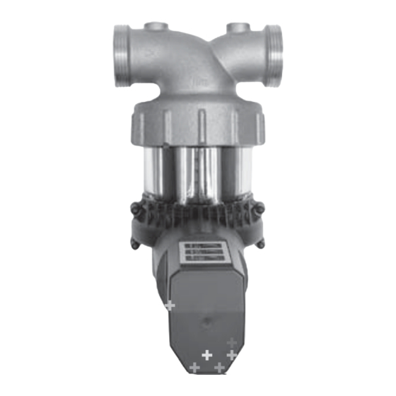
  • Seite 6: Aufbau/Technische Daten

    2. Aufbau/Technische Daten 2.1. Aufbau Komponenten Netzteil Rückspülautomat...
  • Seite 7: Technische Daten Netzteil

    2.2. Technische Daten Netzteil Eingangsspannung (Input) 100-240 V AC Stromaufnahme (Input) 0.31-0.16 A Ausgangsspannung (Output) 24 V DC Maximal Strom (Output) 0.5 A Leistung (Output) 12 W Typenschild am Netzteil Netzfrequenz 50-60 Hz Arbeitstemperatur Netzteil 0 bis 50°C Luftfeuchtigkeit 20 bis 90% r.F. Schutzklasse Kabellänge 1.8 m...
  • Seite 8: Technische Daten Rückspülautomat

    2.3. Technische Daten Rückspülautomat Für den Rückspülautomat im Besonderen Spannung 24 V DC Arbeitstemperatur El. Motor 0°C bis +50°C Stromaufnahme (Input) 250 mA Typenschild am Rückspülautomat...
  • Seite 9: Einbauort/Installation

    3. Einbauort/Installation 4. Inbetriebnahme Achtung Für die Rückspülung des Filters ist eine ausreichend dimensionierte Abflussleitung vorzusehen. Zur Bestimmung der Spülleistung siehe Montageanleitung Nr. 35 09 458 73 oder Technischen Dokumentation Nr. 37 259 00. Die Abflussleistung ist zu prüfen bei “TIME“-Einstellung von 6 Sekunden.
  • Seite 10: Einstellmöglichkeiten

    5. Einstellmöglichkeiten 5.1. Tastensperre Der Rückspülautomat ist gegen ein ungewolltes Verstellen der gewählten Parameter gesichert. Wird eine Taste betätigt, werden 3 LED’s abge- dimmt dargestellt. Erst durch das Aufheben der Tastensperre wird eine individuelle Einstellung möglich. Die Tastensperre wird durch gleichzeitiges betätigen (2 Sekunden) der Tastenkombination von “INTERVAL“...
  • Seite 11: Interval

    5.2. INTERVAL 5.3. START „INTERVAL“ definiert den Zeitabstand zwischen „START“ definiert in wie vielen Stunden nach den Rückspülungen. der Inbetriebnahme die nächste Rückspülung entsprechend dem eingestellten Intervall Mit der INTERVAL-Einstellung kann die vorgenommen wird. Werkseinstellung 60 d verändert werden. Bei jedem betätigen der INTERVAL-Taste, wer- Mit der START-Einstellung kann die Werks- den die LED durchgeschaltet.
  • Seite 12: Time

    5.4. TIME 5.5. Einstellbeispiel „TIME“ definiert die Spülzeit pro Filterkammer. Gewünscht wird ein Intervall von 30 Tagen, jede Kammer soll 3 Sekunden rückgespült werden Mit der TIME-Einstellung kann die Werks- und der Rückspülvorgang soll am Abend um einstellung 1 s (Sekunde) verändert werden. 20:00 Uhr stattfinden.
  • Seite 13: Manuelle Auslösung

    6. Manuelle Auslösung 7. Gangreserve/Stromunterbruch Um eine manuelle Auslösung durchzuführen, Bei einem Stromunterbruch während der wird die START-Taste 5 Sekunden lang gedrückt, Rückspülung, wird durch die Gangreserve, unabhängig von der Tastensperre. die aktuelle Rückspülung der Filterkammer Während dem Rückspülen blinken die LED‘s von abgeschlossen.
  • Seite 14: Wartung/Kontrolle

    8. Wartung/Kontrolle 9. Entsorgung Das Netzteil ist wartungsfrei. Die Systemteile des Rückspülautomaten können gemäss den örtlichen Vorschriften entsorgt Durch das betätigen einer der Taster „INTERVAL“, werden. „START oder “TIME“ leuchten die LED’s gemäss der aktuellen Einstellung. Sollten LED’s hierbei nicht leuchten, muss die Spannungsversorgung durch einen Fachmann überprüft werden.
  • Seite 15: Anhang/Eg Einbauerklärung

    10. Anhang/EG Einbauerklärung bel mit Stecker für die Armatur JRG CleanLine (Combi/Filter), für den Einbau in eine Kaltwas- EG Einbauerklärung für unvollständige serleitung, für Wasser bis max. 30°C und max. Maschinen Betriebsdruck von PN16. Die Inbetriebnahme ist solange untersagt, bis Hersteller: Georg Fischer JRG AG die dazugehörenden Komponenten richtig ange-...
  • Seite 16 EN ISO 12100-1:2003 Anhang VII Teil B erstellt wurden und diese Sicherheit von Maschinen, -Grundbegriffe, allgemeine Gestaltungsleitsätze – den Einzelstaatlichen Behörden auf begrün- Teil 1: Grundsätzliche Terminologie, Methodologie detes Verlangen per Post oder elektronisch übermittelt werden EN ISO 12100-2:2003 Sicherheit von Maschinen, -Grundbegriffe, allgemeine Gestaltungsleitsätze –...
  • Seite 17: Contre-Courant F

    Notice d’utilisation et d’entretien JRG CleanLine Filter Dispositif de rinçage à contre-courant 17 – 32 1371.025/.032 1871.025/.032 8171.300...
  • Seite 18 1. Remarques 1.1. Symboles de sécurité 1.2. Application/Fonction 1.3. Personnel qualifié 1.4. Danger pour cause d’énergie électrique 1.5. Danger dû à la rotation de la tubulure d’évacuation 1.6. Emballage/Transport 1.7. Conformité/Déclaration d’incorporation 2. Structure/Fiche technique 2.1. Structure 2.2. Fiche technique du bloc d’alimentation 2.3.
  • Seite 19: Remarques

    Attention le mode d’emploi et instruction de maintenance Ce symbole donne une information dont du filtre JRG CleanLine, No. 35 09 458 71 respec- le non- respect pourrait entraîner des tivement JRG CleanLine Combi, No. 35 09 458 72 dommages importants. Il convient de sont à...
  • Seite 20: Application/Fonction

    1.2. Application/Fonction L‘entreprise Georg Fischer JRG SA décline Le dispositif électrique de rinçage à contre-cou- toute responsabilité en cas d’installations rant pour la robinetterie JRG CleanLine (Combi/ inappropriées. Filtre) permet le rinçage automatique à contre- courant de la cartouche filtrante.
  • Seite 21: Emballage/Transport

    1.6. Emballage/Transport 1.7. Conformité/Déclaration d’incorporation Les données relatives au produit, p. ex. numéro Veuillez uniquement transporter et de série ou le marquage CE se trouvent sur la stocker le dispositif de rinçage à plaque signalétique (voir chapitre 2 „Structure/ contre-courant dans son emballage Fiche technique“).
  • Seite 22: Structure/Fiche Technique

    2. Structure/Fiche technique 2.1. Structure Composants Bloc d’alimentation Dispositif de rinçage à contre-courant...
  • Seite 23: Fiche Technique Du Bloc D'alimentation

    2.2. Fiche technique du bloc d’alimentation Tension d’entrée (Input) 100-240 V AC Courant absorbé (Input) 0.31-0.16 A Tension de sorti (Output) 24 V DC Courant max (Output) 0.5 A Puissance absorbée (Output) 12 W Plaque signalétique sur Fréquence du réseau 50-60 Hz le bloc d’alimentation Temp.
  • Seite 24: Fiche Technique Du Dispositif De Rinçage À Contre-Courant

    2.3. Fiche technique du dispositif de rinçage à contre-courant En particulier pour le dispositif de rinçage à contre-courant Tension 24 V DC Température ambiante, 0°C à +50°C moteur électrique Courant absorbé (Input) 250 mA Plaque signalétique sur le dispositif de rinçage à contre-courant...
  • Seite 25: Emplacement/Installation

    3. Emplacement/Installation 4. Mise en service Attention Pour le rinçage du filtre à contre- courant, il convient de prévoir une conduite d’évacuation suffisamment dimensionnée. Pour la détermination de la capacité de rinçage, voir l’ins- truction de montage, No. 35 09 458 73 ou la documentation technique, No.
  • Seite 26: Possibilités De Réglage

    5. Possibilités de réglage 5.1. Verrouillage des touches Le dispositif de rinçage à contre-courant est assuré contre le dérèglement involontaire des paramètres sélectionnés. Si une touche est actionnée, l’intensité des 3 LED diminue. C’est uniquement après avoir annulé le ver- rouillage des touches qu’un réglage individuel est possible.
  • Seite 27: Interval

    5.2. INTERVAL 5.3. START „INTERVAL“ définit l’intervalle de temps entre „START“ définit dans combien d’heures après la deux rinçages à contre-courant. mise en service, le prochain rinçage à contre- courant doit être effectué conformément à Le réglage INTERVAL permet de modifier les l’intervalle réglé.
  • Seite 28: Time

    5.4. TIME 5.5. Exemple de réglage „TIME“ définit le temps de rinçage par chambre Un intervalle de 30 jours est souhaité, chaque du filtre. chambre doit être rincée à contre-courant pendant 3 secondes et le processus de rinçage Le réglage TIME permet de modifier le réglage à...
  • Seite 29: Déclenchement Manuel

    6. Déclenchement manuel 7. Réserve de marche/Coupure de courant Un déclenchement manuel s’effectue en En cas de coupure de courant pendant le rinçage maintenant l’appui sur la touche START pendant à contre-courant, l’actuel rinçage à contre- 5 secondes, indépendamment du verrouillage courant de la chambre du filtre est interrompu des touches.
  • Seite 30: Maintenance/Contrôle

    8. Maintenance/Contrôle 9. Elimination Le bloc d’alimentation est exempt de mainte- Les composants du système du dispositif de nance. rinçage à contre-courant peuvent être éliminés conformément aux prescriptions locales en En actionnant l’une des touches „INTERVAL“ vigueur. ou „START ou “TIME“, les LED s’allument en fonction du réglage actuel.
  • Seite 31: Annexe/Déclaration D'incorporation

    10. Annexe/Déclaration d’incorporation JRG CleanLine (Combi/filtre), montage sur tuyauterie d’eau froide, pour une température Déclaration d‘incorporation CE pour machines d’eau de 30°C max et une pression de fonction- incomplètes nement PN16. La mise en service est interdite, jusqu’à ce que Fabricant: Georg Fischer JRG AG les composant soient correctement connectés.
  • Seite 32 EN ISO 12100-1:2003 mément à l‘annexe VII, partie B ont été établis Sécurité des machines, notions fondamentales, principes généraux de conception et transmis par poste ou électroniquement Partie 1: Technologie de base terminologie, aux autorités compétentes et ceci sur demande méthodologie justifiée EN ISO 12100-2:2003...
  • Seite 33: Automatico In Controcorrente I

    Istruzioni d’uso e manutenzione JRG CleanLine Filter Dispositivo per il lavaggio automatico in controcorrente I 33 – 48 1371.025/.032 1871.025/.032 8171.300...
  • Seite 34 1. Avvertenze 1.1. Simboli di sicurezza 1.2. Uso/Funzionamento 1.3. Personale specializzato 1.4. Rischio d‘energia elettrica 1.5. Pericolo di rotazione del tubo di scarico 1.6. Imballaggio/Trasporto 1.7. Conformità/Dichiarazione d’incorporazione EG 2. Montaggio/Dati tecnici 2.1. Montaggio 2.2. Dati tecnici alimentatore 2.3. Dati tecnici dispositivo per il lavaggio automatico in controcorrente 3.
  • Seite 35: Avvertenze

    A questo proposito bisogna anche osservare le istruzioni per il mon- Attenzione taggio del filtro JRG CleanLine N. 35 09 458 73 Questo simbolo richiama l’attenzione su e le istruzioni d’uso e manutenzione del filtro un’informazione, la cui inosservanza può...
  • Seite 36: Uso/Funzionamento

    1.2. Uso/Funzionamento L‘azienda Georg Fischer JRG AG non si assume Il dispositivo elettrico sul rubinetto JRG CleanLine nessuna responsabilità in caso di installazione (Combi/Filtro) serve per effettuare automatica- impropria. mente il lavaggio dell‘inserto filtro a maglia fine. Il lavaggio in contro-corrente può essere im- Picco di tensione postato in modo personalizzato (frequenza;...
  • Seite 37: Imballaggio/Trasporto

    1.6. Imballaggio/Trasporto 1.7. Conformità/Dichiarazione d’incorporazione EG Le informazioni sul prodotto, per esempio nu- Trasportare e conservare il dispositivo mero di serie e marchio CE, sono riportate sulla automatico per il lavaggio in contro- targhetta (vedere Capitolo 2 „Montaggio/Dati corrente solo nella sua confezione tecnici“).
  • Seite 38: Montaggio/Dati Tecnici

    2. Montaggio/Dati tecnici 2.1. Montaggio Componenti Alimentatore Dispositivo...
  • Seite 39: Dati Tecnici Alimentatore

    2.2. Dati tecnici alimentatore Tensione di ingresso (Input) 100-240 V AC Assorbimento di corrente (Input) 0.31-0.16 A Tensione di uscita (Output) 24 V DC Potenza massima (Output) 0.5 A Potenza assorbita (Output) 12 W Targhetta Frequenza di rete 50-60 Hz sull’alimentatore Temperatura funzionamento alimentatore da 0 a 50°C...
  • Seite 40: Dati Tecnici Dispositivo Per Il Lavaggio Automatico In Controcorrente

    2.3. Dati tecnici dispositivo per il lavaggio automatico in controcorrente In particolare per il dispositivo automatico di lavaggio Tensione 24 V DC Temperatura di esercizio da 0°C a +50°C motore elettrico Assorbimento di corrente 250 mA (Input) Targhetta sul dispositivo automatico di lavaggio...
  • Seite 41: Punto D'installazione/Installazione

    3. Punto d’installazione/Installazione 4. Messa in funzione Attenzione Per il lavaggio in controcorrente del filtro bisogna procurarsi un tubo di scarico adeguatamente dimensionato. Per determinare la capacità di lavaggio vedere le istruzioni per il montaggio n. 35 09 458 73 oppure la documenta- zione tecnica n.
  • Seite 42: Possibilità Di Regolazione

    5. Possibilità di regolazione 5.1. Blocco tasti Il dispositivo è protetto contro cambiamenti involontari del parametro selezionato. Se viene premuto un tasto, si accendono 3 LED grigi. Una singola regolazione è possibile solo disatti- vando il blocco tasti. Il blocco tasti si disattiva premendo contempo- raneamente (per 2 secondi) la combinazione dei tasti “INTERVAL“...
  • Seite 43: Interval

    5.2. INTERVAL 5.3. START „INTERVAL“ definisce il lasso di tempo che „START“ definisce quante ore dopo la messa in intercorre fra un lavaggio e l‘altro. funzione viene effettuato il lavaggio successivo secondo l’intervallo prefissato. Con l’impostazione INTERVAL si può cambiare l’impostazione di fabbrica di 60 giorni.
  • Seite 44: Time

    5.4. TIME 5.5. Esempio di impostazione „TIME“ definisce la durata del lavaggio per Se si desidera programmare un intervallo di camera filtro. 30 giorni, che ogni camera debba essere lavata per 3 secondi e che la procedura di lavaggio Con l’impostazione TIME può essere cambiata debba avvenire di sera alle ore 20,00.
  • Seite 45: Attivazione Manuale

    6. Attivazione manuale 7. Riserva di carica/Interruzione di corrente Per eseguire un’attivazione manuale, si deve Se si ha un’interruzione di corrente durante premere il tasto START per 5 secondi, indipen- il lavaggio, questo viene comunque portato a dentemente dal blocco tasti. Durante il lavaggio termine grazie ad una riserva.
  • Seite 46: Manutenzione/Controllo

    8. Manutenzione/Controllo 9. Smaltimento L’alimentatore non necessita di manutenzione. I componenti del dispositivo per il lavaggio auto- matico possono essere smaltiti conformemente Premendo i tasti „INTERVAL“ , „START o “TIME“ alle normative locali. si accendono i LED a seconda dell’impostazione effettuata.
  • Seite 47: Appendice/Dichiarazione D'incorporazione Eg

    C) Tutti materiali sono certificati in controcorrente, la tensione di ingresso viene convertita da 100-240 Volt a 24 V CC, con cavo di alimentazione di 1,8 m e spina, per valvola JRG CleanLine (Combi/Filtro) per l’installazione in...
  • Seite 48 EN ISO 12100-1:2003 compilata in conformità dell’allegato VII parte Sicurezza del macchinario, concetti di base, principi generali per il design – B e trasmessa, per posta o per via elettronica, Parte 1: Terminologia e metodologia di base in risposta ad una richiesta adeguatamente motivata alle autorità...
  • Seite 49: Automatic Backwash Unit E

    Operating and maintenance instructions JRG CleanLine Filter Automatic backwash unit 49 – 64 1371.025/.032 1871.025/.032 8171.300...
  • Seite 50 1. Notes 1.1. Safety symbols 1.2. Application/Function 1.3. Qualified personnel 1.4. Electric shock hazards 1.5. Danger from rotating drain nozzle 1.6. Packaging/Transport 1.7. Conformity/EG declaration of incorporation 2. Device structure/Specifications 2.1. Device structure 2.2. Technical specifications – power adapter 2.3. Technical specifications – automatic backwash control 3.
  • Seite 51: Notes

    This symbol indicates information which, the Operating and Maintenance Instructions if ignored, can lead to extensive property JRG CleanLine Filter No. 35 09 458 71 resp. damage. The safety instructions must be JRG CleanLine Combi No. 35 09 458 72.
  • Seite 52: Application/Function

    1.2. Application/Function Georg Fischer JRG AG cannot be held liable for The electric backwash control for the JRG any hazards arising from improper use and/or CleanLine (Combi/Filter) is used to automatically faulty installation. backwash the fine filter. All backwash param-...
  • Seite 53: Packaging/Transport

    1.6. Packaging/Transport 1.7. Conformity/EG declaration of incorporation The specifications of the product e.g. serial Please transport and store the auto- number or CE mark can be taken from the matic backwash control only in its nameplates (see chapter 2 “Device structure/ original packaging.
  • Seite 54: Device Structure/Specifications

    2. Device structure/Specifications 2.1. Device structure Components Power adapter Automatic backwash...
  • Seite 55: Technical Specifications - Power Adapter

    2.2. Technical specifications – power adapter Input voltage (Input) 100-240 V AC Current draw (Input) 0.31-0.16 A Output voltage (Output) 24 V DC Maximum power (Output) 0.5 A Power consumption (Output) 12 W Nameplate on power Mains frequency 50-60 Hz adapter Working temperature power adapter 0-50°C...
  • Seite 56: Technical Specifications - Automatic Backwash Control

    2.3. Technical specifications – automatic backwash control For the automatic backwash control in particular Voltage 24 V DC Working temperature of 0°C to +50°C actuator motor Current draw (Input) 250 mA Nameplate on power adapter...
  • Seite 57: Installation Site/Installation

    3. Installation site/Installation 4. Commissioning Warning Ensure a sufficiently large drain line for duly backwashing the filter. To determine the flushing capacity, please see Installation Instructions No. 35 09 458 73 or technical documen- tation No. 37 259 00. Check the discharge capacity by setting “TIME”...
  • Seite 58: Settings

    5. Settings 5.1. Key lock The automatic backwash control is protected against accidental changes of the selected parameters. If a key is pressed, the 3 LEDs are dimmed. Release the key lock to separately adjust the parameters. Push both “INTERVAL” and “TIME” simultane- ously to release the key lock.
  • Seite 59: Interval

    5.2. INTERVAL 5.3. START „INTERVAL“ defines the time interval between „START“ defines the start time of the first back- backwashes. wash after commissioning the device. “INTERVAL” allows you to change the factory “START” allows you to change the factory set- setting (60 d).
  • Seite 60: Time

    5.4. TIME 5.5. Sample settings „TIME“ defines the flushing time per filter The system is backwashed every 30 days, chamber. at 8:00 pm, each chamber for 3 seconds. “TIME” allows you to change the factory setting Settings: (1 s). If you press the “TIME” key, the LEDs will INTERVAL = 30 d flash one at a time.
  • Seite 61: Manual Backwash

    6. Manual backwash 7. Power reserve/Power failure Press “START” for 5 seconds to manually start a In case of power failure, the power reserve backwash at any time. During backwashing, the enables the control to complete the backwash of LEDs will flash from top to bottom. the currently flushed chamber.
  • Seite 62: Maintenance/Checks

    8. Maintenance/Checks 9. Disposal The power adapter is maintenance free. All components of the automatic backwash control can be disposed of according to local Press “INTERVAL” or “START” or “TIME” to have regulations. the LEDs indicate the current setting. If the LEDs do not flash, have the power supply checked by an expert.
  • Seite 63: Appendix/Eg Declaration Of Incorporation

    C) All certified materials Electric backwash unit incl. power adapter 12 W for power supply of the automatic backwash unit, input voltage of 100-240 V converted to 24 V DC, including 1.8 m power cable with plug for valve JRG CleanLine (Combi/Filter) for...
  • Seite 64 EN ISO 12100-1:2003 to Annex VII, Part B has been prepared and can Safety of machinery, – Basic concepts, general principles for design – be made available to national authorities upon Part 1: Basic terminology, methodology reasoned request by mail or email EN ISO 12100-2:2003 Safety of machinery, –...
  • Seite 68 Autres pays Altri paesi Other countries Einbaudatum: Date de montage: Data d‘installazione: Built-in date: Ihr Installateur: Votre installateur: Il vostro installatore: Your plumber: Ident. Nr. 35 09 458 74 / 1.2 / 1.14 / SMS / ©Georg Fischer JRG AG...

Inhaltsverzeichnis