Pilz PSEN ix1 Betriebsanleitung
Vorschau ausblenden
Andere Handbücher für PSEN ix1:
- Betriebsanleitung (8 Seiten) ,
- Betriebsanleitung (8 Seiten)
Inhaltsverzeichnis
20950-03
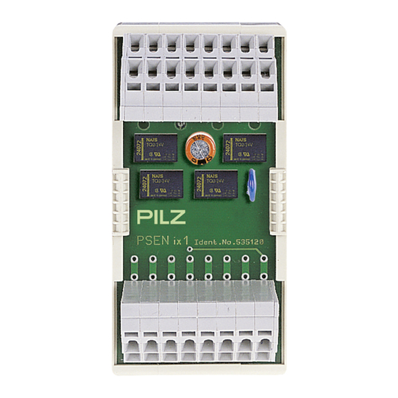
PSEN ix1
Die Schnittstelle PSEN ix1
Mit Hilfe der Schnittstelle PSEN ix1
lassen sich mehrere Sicherheitsschalter
oder Positionsschalter an Sicherheitsschalt-
geräte der Serie PNOZ anschließen und
auswerten.
An das PSEN ix1 dürfen angeschlossen
werden:
• Sicherheitssschalter PSEN 1.1p-12,
PSEN 1.1p-22, PSEN 1.2p-22, PSEN
1.2p-25
• Positionsschalter mit Schließer-/Schließer-
Kombination
• NOT-AUS-Taster mit Öffner-/Öffner-
Kombination
Das PSEN ix1 darf nur an Auswertegeräte
angeschlossen werden, die in der Tabelle im
Abschnitt "Anschlüsse" aufgeführt sind.
Wichtig: Der Einsatz des PSEN ix1
verringert die Klassifizierung nach
EN 60947-5-3 von PDF-M auf PDF-S.
Zu Ihrer Sicherheit
Die Schnittstelle PSEN ix1 erfüllt alle
notwendigen Bedingungen für einen
sicheren Betrieb.
Beachten Sie jedoch nachfolgend aufge-
führte Sicherheitsbestimmungen:
• Installieren und nehmen Sie das Gerät nur
dann in Betrieb, wenn Sie mit dieser
Betriebsanleitung und den geltenden
Vorschriften über Arbeitssicherheit und
Unfallverhütung vertraut sind.
• Verwenden Sie das Gerät nur gemäß
seiner Bestimmung. Beachten Sie dazu
auch die Werte im Abschnitt "Technische
Daten".
• Halten Sie beim Transport, bei der
Lagerung und im Betrieb die Bedingungen
nach EN 60068-2-6, 01/00 ein (siehe
"Technische Daten").
• Nehmen Sie keine eigenmächtigen
Umbauten vor.
Beachten Sie unbedingt die Warnhinweise in
den anderen Abschnitten dieser Anleitung.
Diese Hinweise sind optisch durch Symbole
hervorgehoben.
Wichtig: Beachten Sie die Sicher-
heitsbestimmungen, sonst erlischt
jegliche Gewährleistung.
Zulassungen
The interface PSEN ix1
The PSEN ix1 interface enables
several safety switches or position switches
to be connected to safety gate monitors or
programmable safety systems and
evaluated.
The following may be connected to the
PSEN ix1:
• Safety switches PSEN 1.1p-12, PSEN
1.1p-22, PSEN 1.2p-22, PSEN 1.2p-25
• Position switches with N/O / N/O
combination in safety circuits
• E-STOP button with N/C / N/C
combination
The PSEN ix1 may only be connected to
evaluation devices that are listed in the table
under section "Connections".
Notice: The use of PSEN ix1 lowers
classification in accordance with
EN 60947-5-3 from PDF-M to PDF-S.
For your safety
The PSEN ix1 interface meets all the
necessary conditions for safe operation.
However, always ensure the following safety
requirements are met:
• Only install and commission the unit if you
are familiar with the information in these
operating instructions, as well as the
relevant regulations concerning health and
safety at work and accident prevention.
• Only use the unit for the purpose for which
it is intended. Please note also the values
stated in the "Technical details" section.
• Transport, storage and operating
conditions should all conform to EN
60068-2-6, 01/00 (see "Technical details").
• Do not make any unauthorised
modifications.
You must observe the warning notes given
in other parts of these operating instructions.
These notes are highlighted via symbols.
Notice: Failure to comply with the
safety requirements will render the
guarantee invalid.
Approvals
- 1 -
L'interface PSEN ix1
L'interface PSEN ix1 permet le
raccordement de plusieurs capteurs de
sécurité ou interrupteurs de position sur un
relais de contrôle de protecteurs mobiles ou
un automate de sécurité.
Les éléments suivants peuvent être
raccordés au PSEN ix1:
• capteurs de sécurité PSEN 1.1p-12,
PSEN 1.1p-22, PSEN 1.2p-22, PSEN
1.2p-25
• interrupteurs de position avec contact F/F
• poussoir AU avec contact F/F
Le PSEN ix1 doit être raccordé uniquement
aux unités de contrôle indiquées dans le
tableau du chapitre "raccordement".
Important : l'utilisation du PSENix1
diminue la classification d'après EN
60947-5-3 de PDF-M à PDF-S
Pour votre sécurité
L'interface PSEN ix1 satisfait à toutes les
conditions nécessaires pour un
fonctionnement sécuritaire.
Toutefois, vous êtes tenu de respecter les
prescriptions de sécurité suivantes:
• Vous n'installerez l'appareil et ne le
mettrez en service qu'après vous être
familiarisé avec le présent manuel
d'utilisation et les prescriptions en vigueur
sur la sécurité du travail et la prévention
des accidents.
• N'utilisez l'appareil que conformément à
sa définition. Respectez les valeurs
indiquées dans les "Caractéristiques
techniques".
• Pour le transport, le stockage et
l'utilisation, respectez les exigences de la
norme EN 60068-2-6, 01/00 (voir
"Caractéristiques techniques")
• N'effectuez pas de modifications non
autorisées.
Respectez impérativement les
avertissements dans les autres paragraphes
du présent manuel d'utilisation. Ces
avertissements sont signalés par des
symboles visuels.
Important : Respectez les consignes
de sécurité, sinon la garantie devient
caduque.
Homologations
Inhaltsverzeichnis

Verwandte Anleitungen für Pilz PSEN ix1


Inhaltszusammenfassung für Pilz PSEN ix1
- Seite 1 • NOT-AUS-Taster mit Öffner-/Öffner- combination Le PSEN ix1 doit être raccordé uniquement Kombination The PSEN ix1 may only be connected to aux unités de contrôle indiquées dans le Das PSEN ix1 darf nur an Auswertegeräte evaluation devices that are listed in the table tableau du chapitre "raccordement".
- Seite 2 Description de l'appareil Gerätemerkmale: Unit features: Particularités: • Reihenschaltung von max. 13 PSEN ix1 • Connection in series for max. 13 PSEN • Mise en série de 13 PSEN ix1 max. möglich ix1 possible possible • Anschlussmöglichkeit für • Connection for Raccordement possible de : - max.
- Seite 3 : mettre schaltern/Positionsschaltern: PNOZ ix1 in PNOZ ix1 in series (see illustration les PSEN ix1 en série ( voir exemple Reihe schalten (siehe Abbildung "Reihen- "Connecting PSEN ix1 in series"). From "Mise en série de PSEN". Ponter les schaltung von PSEN).
- Seite 4 Connecting the safety switches/position Raccordement des capteurs/interrupteurs AUS anschließen switches/E-STOP de position/poussoir d'AU max. 13 PSEN ix1, link Y8-Y9 from the max. 13 PSEN ix1, ponter Y8-Y9 à partir max. 13 PSEN ix1, Y8-Y9 ab zweitem second device du 2ème appareil Gerät brücken...
-
Seite 5: Betrieb
Betrieb Operation Fonctionnement Das Gerät ist betriebsbereit, wenn die LED The unit is ready for operation when the L’appareil est prêt à fonctionner lorsque la "POWER" dauerhaft leuchtet. "POWER" LED is lit continuously. " LED POWER " reste allumée. Statusanzeigen: Status indicators: Affichages d’état : •... -
Seite 6: Anschlussbeispiel
Evaluation (PNOZ X3) of 9 safety switches Unité de contrôle (PNOZ X3) avec 9 schaltern über 3 in Reihe geschaltete via 3 PSEN ix1 units connected in series. capteurs de sécurité câblés à l’aide de 3 PSEN ix1. Bei Reihenschaltung ab dem 2. - Seite 7 - 7 -...
- Seite 8 0224 2360180, Fax: 0224 2360184, E-Mail: pilz.tr@pilz.de Pilz Automation Safety L.P., 734 354-0272, Fax: 734 354-3355, E-Mail: info@pilzusa.com www.pilz.com ✆ Pilz GmbH & Co. KG, Sichere Automation, Felix-Wankel-Straße 2, 73760 Ostfildern, Deutschland, +49 711 3409-0, Fax: +49 711 3409-133, E-Mail: pilz.gmbh@pilz.de - 8 -...