Technics RS-D400 Serviceanleitung
Service
DOLBY
B.C
NR
•Please use this manual together with the service manual for
model
No.
RS-D400
•This
Service
Manual
original
RS-D400 (for [E] mark areas) and RS-D400 (for [EGA]
mark areas).
PARTS
COMPARISON
Please revise the original
RS-D400 (Original: [El mark areas) to conform to the changes
shown
herein.
If new part numbers are shown, be sure to use them when
ordering
parts.
Ref.
No.
RI, 2
Resistors
R92
Resistor
R98, 99
A
Resistors
R207
Resistor
R601, 602
Resistors
R603, 604
Resistors
R605, 606
Resistors
C65, 66
Capacitors
C67
Capacitor
0601, 602
Transistors
0601
Diode
L7
Bias
J3
DIN Jack
9
Case
Front Panel Assembly
11
23
Back
36
DIN Jack Angle
37
Latch
38
Shield
39
Lug Terminal
126
Wire Clamper
153
Erase Head Assembly
189
Head Base Plate Angle
Design and specifications are subject to change without notice.
* 'Dolby' and the double-D symbol are trademarks of Dolby Laboratories Licensing Corporation.
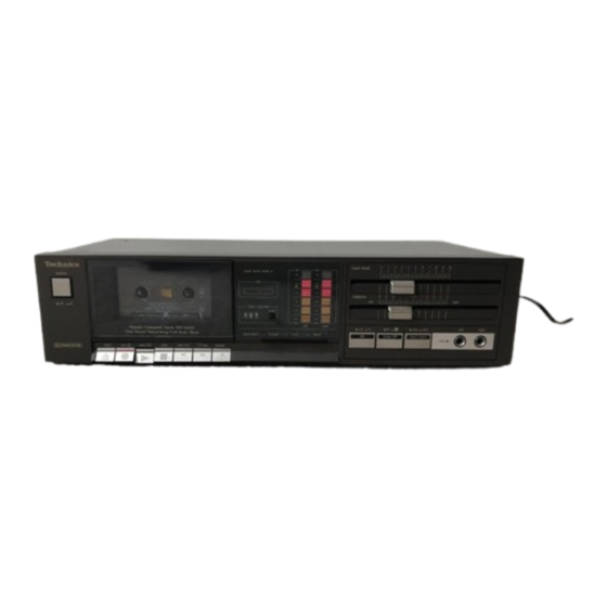
Technics
Dolby B • C NR-Equipped
Stereo
Cassette
order
No.
HAD84062829C8.
indicates
the main differences
TABLE:
parts list in the Service Manual
Part Name & Description
Oscillation
Coil
Foot
Chassis
Plate
Manual
Deck
between;
Part
Numbers
RS-D400
(For [E] mark areas)
(For [EGAI mark areas)
ERQ14LKR56
ERD25FJ562
ERD25TJ123
ERQ14LKR56
ERD25TJ123
ERD25FJ562
ERD25FJ472
ERD25TJ273
ERD25TJ225
ECFDD152KVY
ECFDD272KVY
ECKD2H472PE
2SJ40CD
1S2473LF
QLB0198KA
QLB0207K
QJS2003H
QKA1094
SKL294
SGWSD400-SE
SGWSD400SEGA
SGWSD400-KE
SGWSD400KEGA
SGP6280
SGP6340
QMA4645
QKJ0678
SMC1173
RJT202B
QTD1181
QTD1333
QWY2138G
QXV0213
QMA4868
Matsushita Electric Trading Co., Ltd.
ORDER
NO. HAD84072863A2
Cassette
RS-D400
Color
(K).. .Black Type
(S)...Silver
Color
Area
IEGA]
... ..F.R. Germany
.
• Important safety notice
Components
identitied
by
mark
have special
characteristics
important
for safety.
When
replacing
any of these
components.
only manufacturer's
specified
parts.
Remarks
RS-D400
Deleted
Corrected
Added
Corrected
Added
Added
Added
Added
Added
Added
Added
Silver Type
Black Type
Added
Added
Added
Added
Added
PO. Box 288. Central Osaka Japan
Deck
Type
use
Inhaltsverzeichnis

Verwandte Anleitungen für Technics RS-D400


Inhaltszusammenfassung für Technics RS-D400
- Seite 1 IEGA] ..F.R. Germany PARTS COMPARISON TABLE: Please revise the original parts list in the Service Manual RS-D400 (Original: [El mark areas) to conform to the changes • Important safety notice Components identitied mark have special shown herein.
- Seite 2 RS-D400 MECHANICAL PARTS LOCATION * For [El mark areas. * For [EGAJ mark areas. APPLY ROCOL APPLY PASTE PASTE APPLY APPLY ROCOL APPLY MOLYCOAT APPLY EM.20L MOLYCOAT EM.20L • CABINET PARTS LOCATION * For [El mark areas. AC power transformer...
- Seite 3 SCHEMATIC DIAGRAM MAIN CIRCUIT SECTION 011. 2SD1330R ISS133 M5218L 2SD636 2SD636 PRE AMP MUTING REC AMP SWITCHING MUTING 2SB641 SWITCH'NG DOLBY ca19 u 13 cals SI-S Sl-l 22' aocat ca21 LINE •o.nv LINE OUT - 3.1w J': MIC 'N (LCH) DIN JACK CIRC RECORD,'PLAYBACK...
- Seite 4 RS.D400 NOTES: Record/playback switch (shown in playback position). • SI.I&SI.IO: • Input select switch (shown in line in position). • 'VS2-4 Dolby NR switch (shown in OFF position). Metal tape select switch (shown in Croz position). • S4-1, S4-2 as— 01'.
-
Seite 5: Connection Diagram
RS.D400 RS.D400 RS.D400 CIRCUIT BOARD AND WIRING CONNECTION DIAGRAM MAIN CIRCUIT BOARD LUG TERMINAL LUG TERMINAL (To mechanism unit) ERASE HEAD (To shield ptate) MOTOR FF/REW TRANSF SWITCH 123456 illi ,fIJl DIN JACK CIRCUIT BOARD RECORD/PLAYBACK HEAD sB9 sr Erase current adjustment jumper... - Seite 6 RS-D400 RS.D400 SUPPLY CIRCUIT BOARD LUG TERMINAL LUG TERMINAL (To shield plate) go mechanism unit) ERASE HEAD MOTOR Tl : AC POWER S6: FFIREW TRANSFORMER SWITCH i lil POWER CORD RECORD/PLAYBACK HEAD SFsr-R¯ POWER SWITCH I CIRCUIT BOARD S7: POWER...
- Seite 7 ORDER NO. HAD84062829C8 Service Manual Cassette Deck RS-D400 Dolby B C NR-Equipped Stereo Cassette Deck Color DOLBY (K)...Black Type (S)...Silver Type Color Area All European areas except United Kingdom. [EKI..United Kingdom. Asia, Latin America, Middle East Africa areas. [XLI..
- Seite 8 RS.D400 CONTENTS ITEM PAGE ITEM PAGE • Location of Controls and Components • Circuit Boards and Wiring Connection • Disassembly Instructions Diagram • Measurement and Adjustment Methods • Mechanical Parts Location • Block Diagram..(included Parts List) • Schematic Diagram •...
- Seite 9 RS.D400 RS.D400 • DISASSEMBLY INSTRUCTIONS Shown To remove — Remove — Ref. Procedure fig. — • Push the eject button • 2 screws • 2 screws • Remove the counter belt ..(l) Serial Number • Pull out the connectors Plate Mechanism unit •...
- Seite 10 RS.D400 Set switches and controls in the following positions, unless otherwise specified. NOTES: • Make sure heads clean • Tape selector: Normal Playback frequency Condition: Equipment: • Make sure capstan and pinch roller are clean • Input selector: Line in •...
- Seite 11 Overall frequency response chart (Normal) Test equipment connection is shown in fig. 15. (Recording equalizer is fixed) BLOCK Insert the normal reference blank tape (QZZCRA). Record/91ayback Make connections as shown in fig. 11. 6009 head Place UNIT into record mode. Place UNIT into normal tape mode and insert the normal •m Supply a 1 kHz signal through...
-
Seite 12: Block Diagram
RS.D400 BLOCK DIAGRAM Record,'playback head Sl-l Sl-3 Sl.5 S2-l S2-3 Cr02/ PB/ON Metal Record mode Test tape LINEOUT Dolby NR Oscilloscope JACK Playback EQ REC A M p POWER suppL REC,EQ ter) AF oscillator RECORD/PLAYBACK H EAD • Oscilloscope —dB HALF/ONI B/C/OFF LINE... - Seite 13 RS.D400 RS-D400 SCHEMATIC DIAGRAM MAIN CIRCUIT SECTION 03, 4 05—10 MS219L 2SD1330 ISS133T 2S0636 MUTING REC AMP SWITCHING MUTING 2SB641 SWITCHING 51 -Y Sl-l •8 ftv LINE IN LINE OUT RECORO.'PLAYBACK HEAD 100' RECORO'PLAYBACK HEAD ISS133T accl Sl-a 52-2 LINE 'N (RCH)
- Seite 14 RS.D400 RS.D400 NOTES: ELECTRICAL PARTS LIST • SI.I'VSI.IO Record/playback switch (shown in playback position). • S2-1 Input select switch (shown in line in position), NOTES: RESISTORS CAPACITORS Dolby NR Switch (shown in OFF position). .Carbon ECBA -Ceramic ECOE .Polyester film S4-1, S4-2 Metal tape select switch...
- Seite 15 CIRCUIT BOARDS WIRING CONNECTION DIAGRAM CONNECTORS (3 Pin) (6 Pin) .For all European areas except POWER SUPPLY CIRCUIT BOARD OMAIN CIRCUIT BOARD United Kingdom. IEKI(XAKXLI TERMINAL 00 mechanism unit) ERASE HEAD MOTOR CNIO• AC POWER F FIREW TRANSFORMER SWITCH Removing contacts 1231SE Push the pawl Of a contact...
- Seite 16 RS.D400 IG CONNECTION DIAGRAM , For all European areas except POWER SUPPLY CIRCUIT BOARD United Kingdom. [EKI[XAIXLI TERMINAL (TO mechanism unit) ERASE HEAD MOTOR AC POWER TRANSFORMER SWITCH .Asia, Latin America, Middle East and S8: AC POWER Africa areas. VOLTAGE SELECTOR AC POWER -Ill...
-
Seite 17: Parts Location
RS.D400 RS.D400 RS.D400 MECHANICAL PARTS LOCATION • CABINI APPLY MOLYCOAT APPLY EM-2 MOLYCOAT EM.20L &APPLY ROCOL PASTE APPLY AK-152 APPLY AERO APPLY GREASE MOLYCOAT Power switch APPLY MOLYCOAT EM.20L APPLY EM.20L ROCOL pASTE APPLY MOLYCOAT To tape EM.20L countOf APPLY ROCOL APPLY MOLYCOA... -
Seite 18: Replacement Parts List
RS.D400 RS-D400 CABINET PARTS LOCATION tEKIXAIXL1 (EIEKI[XL) APPLY MOLYCOAT APPLY MOLYCOAT tXAJ (Eli EM.20L IAC power t transformer SAPPLY ROCOL PAST Power supply circuit board -Y AK.152 APPLY AERO APPLY Power Switch c ircuit board S GREASE MOLYCOAT APPLY MOLYCOAT EM.20L... - Seite 19 Messung, wie oben beschrieben für Anfang, mittleren Teil und Ende des Testbandes wiederholen mit der Service-Anieitung für Modell Schwankung wie folgt bestimmen: ft-f2 RS-D400. Schwankung = 3000 f1 = Maximalwert f2 = Minimalwert Anm.: NORMALWERT: Mes: Wenn nicht anders vorgeschrieben, Drehschalter...
- Seite 20 Gesamtverstärkung Bedingung: Meßgerät: Gesamtfrequenzgang Bedingung: Meßgerät: • Aufnahme und Wiedergabe • Röhrenvoltmeter Gitsregler VR wie in • Aufnahme und Wiedergabe • Röhrenvoltmeter • Betriebsart: Norma)band • NF-Generator • Betriebsart "Normalband" • NF-Generator • Eingangsregler: • Abschwächer Rallschraubenzieher • Betriebsart "Croa Band" •...
- Seite 21 3000 f1 = valeur maximale Ceci est å utiliser conjointement avec le manuel Remarque: fi = valeur minimale d'entretien du modéle No. RS-D400. Avant de mesurer et régl Valeur standard: correcte (pour la méthoc (Le compensateur d'enrt Brancher les appare...
- Seite 22 Equipement: Brancher les appareils comme indiqué dans la Fig. 15. • Voltmétre électronique • Bande étaion vierge >rminer Introduire la bande étalon vierge (QZZCRA). • Atténuateur .QZZCRA pour bande normale Placer I'UNITE en mode d'enregistrement. • Oscillateur .QZZCRX pour bande croz Appliquer le signal de 1kHz de l'oscillateur AF å...
- Seite 23 Efectuar las mediciones de la misma manera que antes (al comienzo, mitad y final de la cinta) y determinar la para el modelo No. RS-D400. diferencia entre los valores måximo y minimo. Calcular de la forma siguiente: ft-f2 fi = valor måximo, fa = valor minimo...
- Seite 24 Equipo: CondiciÖn: Equipo: Respuesta • VTVM • Resistor (600Q) • Modo de reproducciön/ frecuencia total • Oscilador de AF • Cinta de prueba grabaciön • ATT (Cinta en blanco de referencia) • Modo de cinta normal • Oscilador de AF •...