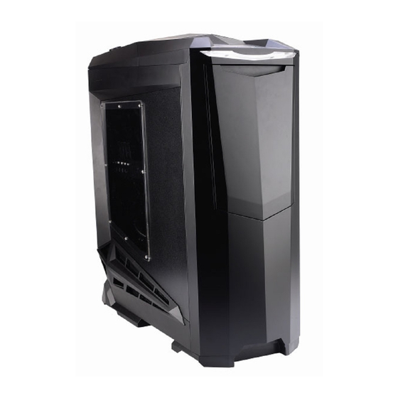
SilverStone SST-RV01B Handbuch
Rv01 serie

Verwandte Anleitungen für SilverStone SST-RV01B


Inhaltszusammenfassung für SilverStone SST-RV01B
-
Seite 2: Specifications
SERIES SERIES Specifications Model SST-RV01B (black) SST-RV01B-W (black + window) Color Matte black Material Reinforced plastic outer shell, 0.8mm SECC body Motherboard SSI EEB, SSI CEB, Extended ATX, ATX, Micro ATX Drive Bay Exposed 5.25” x 5 Internal 3.5” x 6... -
Seite 3: Disassemble Chart
SERIES SERIES Disassemble Chart FRONT I/O CARD SUPPORT SilverStone SST-CP05 VENT FRONT I/O Pin Definition INCLUDE PACKAGE... - Seite 4 SERIES SERIES lnstallation Guide Поверните рукоятку в положение Please follow the direction and rotate “UNLOCK”, как показано на рисунке, the knob to “UNLOCK” position as затем сместите назад и снимите shown, then pull backward to remove the top cover from the chassis. с...
- Seite 5 SERIES SERIES lnstallation Guide Для того чтобы вынуть фиксатор Please remove two thumb screws to карты расширения, удалите два remove the expansion card supporter винта с накатанной головкой. as shown. Bit t e ent f e rn e n S ie d i e z we i Fingerschrauben,um den Träger der Erweiterungskarte wie gezeigt zu entfernen.
- Seite 6 SERIES SERIES lnstallation Guide Приведите нажимную кнопку 5,25 Press the 5.25” drive bay push button to -дюймового отсека в положение “unlock” position as shown in the diagram. “unlock”, как показано на схеме. Drücken Sie den Knopf des 5.25” Laufwerksständers in die "UNLOCK” (ENTRIEGELN)-Position, wie in der Abbildung gezeigt.
- Seite 7 SERIES SERIES lnstallation Guide Приведите нажимную кнопку 5,25-дюймового Press the 5.25” drive bay push buttons to “lock” position to secure optical drive. Press down отсека в положение “lock”, чтобы закрепить on the front door again to enable it to close on оптический...
- Seite 8 SST-CP05 SATA-Festplattenlaufwerke mit Hot-Swap-Funktion, d.h. Austausch ohne Stromabschaltung,unterstützen.) Remettez le casier dans le boîtier. (En option le SilverStone SST-CP05 peut supporter des disques durs SATA qui ne possèdent pas la fonction de montage à chaud). Reinstale la bandeja de disco duro en el chasis.
- Seite 9 SERIES SERIES lnstallation Guide Надежно закрепите опоры Please fasten and secure the motherboard материнской платы (ШУРУП D). standoffs (SCREW D) as required. Then Затем установите материнскую install your motherboard and secure with screws (SCREW C). плату и закрепите ее шурупами (ШУРУП...
- Seite 10 SERIES SERIES lnstallation Guide Установите блок питания, как показано Please install your power supply as shown, н а р и с у н к е , в ы р о в н я й те е го с align with the screw holes and secure with отверстиями...
- Seite 11 SERIES SERIES lnstallation Guide Установите на место боковые Reinstall the side panels onto the main панели корпуса. chassis. Bringen Sie die Seitenteile wieder am Hauptgehäuse an. Réinstallez les panneaux latéraux sur le boîtier Reinstale los paneles laterales en el chasis principal. Reinstallare i pannelli laterali sul chassis.
- Seite 12 SERIES SERIES Appendix 1 : Filter removal guide Открутите 5 шурупов, указанных Please remove 5 screws shown in на диаграмме, чтобы снять фильтр the diagram to remove the side panel filter. боковой панели. muss man sicher sein,dass alle notwendige Kabel und Leitung in Verbindung gebracht werden.und dann das Panel wieder einlegen und mit Schrauben befestigen.
- Seite 13 SERIES SERIES Please press on the power supply filter Нажмите на рукоятку фильтра бл о к а п ита ния , к ак по к аз а н о handle as shown then pull it to remove н а р и с у н к е , и з ат е м в ы н ьт е from the chassis.
- Seite 14 SERIES SERIES Установите прилагаемые крепежные Install the included radiator mounting подставки радиатора и прикрепите supporters and secure it together the их к радиатору шурупами. radiator and its screws. B r i n g e n S i e d e n b e i g e f ü g t e n Träger der Kühlkörper-Halterung a n u n d b e f e s t i g e n S i e d i e s e z u s a m m e n m i t d e m K ü...
- Seite 15 SERIES SERIES Remark: 170mm SIDE PANEL COOLER Motherboard Maximum height for CPU cooler is 170mm Maximum depth for power supply is 295mm...
- Seite 16 SERIES SERIES Remark 70mm The gap between I/O and top cover is 70mm Acceptable connector Unacceptable connector (Over 70mm tall with adaptor)
- Seite 17 ovember, 2008 08810...