Siko LE100M12 Originalmontageanleitung
Linear encoder

Verwandte Anleitungen für Siko LE100M12


Inhaltszusammenfassung für Siko LE100M12
- Seite 1 LE100M12 Linear Encoder Deutsch Originalmontageanleitung Seite 2 Linear Encoder English Translation of the Original Installation Instructions page 14 245/16...
-
Seite 2: Inhaltsverzeichnis
4 Installation 4.1 Mechanische Montage 4.2 Montage Magnetband 4.3 Montage Linear Encoder 4.4 Elektrische Installation 5 Inbetriebnahme 6 Fehlerbehandlung 7 Transport, Lagerung, Wartung und Entsorgung 8 Technische Daten LE100M12 · Datum 25.08.2016 · Art. Nr. 87161 · Änd. Stand 245/16... -
Seite 3: Dokumentation
Todesfolge, Sachschäden oder ungeplanten Gerätereaktionen führen können, sofern Sie die gegebenen Anweisungen missachten. Gefährdungen, die zu schweren Körperverletzungen, Sachschäden oder WARNUNG ungeplanten Gerätereaktionen führen können, sofern Sie die gegebenen Anweisungen missachten. LE100M12 · Datum 25.08.2016 · Art. Nr. 87161 · Änd. Stand 245/16... -
Seite 4: Zielgruppe
Geräte/Systeme gemäß den Standards der Sicherheitstech- nik in Betrieb zu nehmen, zu erden und zu kennzeichnen. 2.4 Grundlegende Sicherheitshinweise Explosionsgefahr GEFAHR ` Linear Encoder nicht in explosionsgefährdeten Zonen einsetzen. LE100M12 · Datum 25.08.2016 · Art. Nr. 87161 · Änd. Stand 245/16... -
Seite 5: Identifikation
Ausfall Linear Encoder VORSICHT ` IP-Schutzart bei Montage beachten (siehe Kapitel 8). ` Linear Encoder nicht selbst öffnen. ` Schläge auf das Gerät vermeiden. ` Keinerlei Veränderung am Gerät vornehmen. LE100M12 · Datum 25.08.2016 · Art. Nr. 87161 · Änd. Stand 245/16... -
Seite 6: Montage Magnetband
Ausrichten des Bandes. Nun kann über die restliche Länge die Schutzfolie, unter gleichzeitigem Andruck des Bandes, seitlich heraus- gezogen werden (als Hilfsmittel kann eine Tapetenandrückwalze verwen- det werden). LE100M12 · Datum 25.08.2016 · Art. Nr. 87161 · Änd. Stand 245/16... - Seite 7 Abb. 6. Diese Den optimalen Schutz bietet die Montage in einer Nut wie in sollte so tief sein, dass das Magnetband fast vollständig darin eingebet- tet ist. LE100M12 · Datum 25.08.2016 · Art. Nr. 87161 · Änd. Stand 245/16...
-
Seite 8: Montage Linear Encoder
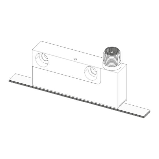
2. Linear Encoder über die zwei Langlöcher auf einer ebenen Arbeitsflä- che befestigen (Befestigungsmaße siehe Datenblatt). Anzugsmoment der Schrauben: 2.5 Nm. Verfahrrichtung cos vor sin Abb. 7: Montage Linear Encoder LE100M12 · Datum 25.08.2016 · Art. Nr. 87161 · Änd. Stand 245/16... - Seite 9 Lage Ref.Punkt P=entspr. Lieferpapiere Lage Ref.Punkt E=entspr. Lieferpapiere min. 0.01 m Abb. 9: Lage Referenzpunkt Magnetband Referenzpunkt periodisch Einmaliger Referenzpunkt Symbolische Darstellung der Pole LE100M12 · Datum 25.08.2016 · Art. Nr. 87161 · Änd. Stand 245/16...
-
Seite 10: Elektrische Installation
• 12 polig Stift M12 A-kodiert. Belegung /sin /cos /ref Ansichtseite = Steckseite WP (Programmierkanal) WR (Programmierkanal) LE100M12 · Datum 25.08.2016 · Art. Nr. 87161 · Änd. Stand 245/16... -
Seite 11: Inbetriebnahme
Hitze und Feuchtigkeit schützen. • Anschlüsse weder durch mechanische noch durch thermische Einflüsse beschädigen. • Vor Montage ist der Linear Encoder auf Transportschäden zu untersu- chen. Beschädigte Linear Encoder nicht einbauen. LE100M12 · Datum 25.08.2016 · Art. Nr. 87161 · Änd. Stand 245/16... -
Seite 12: Technische Daten
0.1 ... 0.35 mm ohne Abdeck- band) 1 V ±100 mV 10.5 ... 30 V DC, bei 25 °C (bei Abstand 0.1 ... 0.35 mm ohne Abdeckband) Ausgangsimpedanz 0 Ω (R >75 Ω) kurzschlussfest Last Signalperiode 1000 μm LE100M12 · Datum 25.08.2016 · Art. Nr. 87161 · Änd. Stand 245/16... - Seite 13 Luftfeuchtigkeit 100 % Betauung zulässig EN 61000-6-2 Störfestigkeit / Immission EN 61000-6-4 Störaussendung / Emission Schutzart IP67 EN 60529, bei montiertem Gegenstecker Vibrationsfestigkeit 200 m/s², 50 Hz ... 2 kHz EN 60068-2-6 LE100M12 · Datum 25.08.2016 · Art. Nr. 87161 · Änd. Stand 245/16...
- Seite 14 4.1 Mechanical mounting 4.2 Mounting the magnetic tape 4.3 Mounting the Linear Encoder 4.4 Electrical Installation 5 Commissioning 6 Trouble shooting 7 Transport, Storage, Maintenance and Disposal 8 Technical data LE100M12 · Date 25.08.2016 · Art. No. 87161 · Mod. status 245/16...
-
Seite 15: Documentation
Danger that may cause minor injury, property damage or unplanned device CAUTION reactions if you disregard the instructions given. LE100M12 · Date 25.08.2016 · Art. No. 87161 · Mod. status 245/16... -
Seite 16: Target Group
Bruising, rubbing, abrasing, seizing of extremities or clothes by touching during operation any movable parts as for example sensor. ` Install protective facilities to prevent people from getting access. LE100M12 · Date 25.08.2016 · Art. No. 87161 · Mod. status 245/16... -
Seite 17: Identification
` When mounting pay attention to the IP type of protection (see chap- ter 8). ` Do not open the Linear Encoder yourself. ` Avoid knocking on the device. ` Do not modify the device in any way. LE100M12 · Date 25.08.2016 · Art. No. 87161 · Mod. status 245/16... -
Seite 18: Mounting The Magnetic Tape
A wallpaper seam roller could be used to assist in applying pressure onto the magnetic tape when fixing it in position. LE100M12 · Date 25.08.2016 · Art. No. 87161 · Mod. status 245/16... - Seite 19 Optimum protection is provided by mounting in a groove as shown in Fig. 6. The groove should be deep enough so that the almost completely mag- netic tape will be embedded in it. LE100M12 · Date 25.08.2016 · Art. No. 87161 · Mod. status 245/16...
-
Seite 20: Mounting The Linear Encoder
2. Fasten the Linear Encoder via tjt two long holes on a level worktop (for the fastening dimensions refer to the data sheet). Tightening torque of the screws: 2.5 Nm. Travel direction cos before sin Fig. 7: Mounting the Linear Encoder LE100M12 · Date 25.08.2016 · Art. No. 87161 · Mod. status 245/16... - Seite 21 Position of the reference point E = as stated in the delivery documentation, min. 0.01 m Fig. 9: Position of the reference point magnetic tape Periodical reference point Unique reference point Magnetic poles - schema LE100M12 · Date 25.08.2016 · Art. No. 87161 · Mod. status 245/16...
-
Seite 22: Electrical Installation
• 12 poles pin M12 A coded. Designation /sin /cos /ref viewing side = plug-in side WP (programming channel) WR (programming channel) LE100M12 · Date 25.08.2016 · Art. No. 87161 · Mod. status 245/16... -
Seite 23: Commissioning
• Do not damage connections through mechanical or thermal impact. • Prior to installation inspect the Linear Encoder for transport damages. Do not install damaged Linear Encoder. LE100M12 · Date 25.08.2016 · Art. No. 87161 · Mod. status 245/16... -
Seite 24: Technical Data
... 0.35 mm without cover strip) 1 V ±100 mV 10.5 ... 30 V DC, at 25 °C (at dis- tance 0.1 ... 0.35 mm without cover strip) Output impedance 0 Ω (R >75 Ω) short-circuit proof Load Signal period 1000 μm LE100M12 · Date 25.08.2016 · Art. No. 87161 · Mod. status 245/16... - Seite 25 / immis- sion EN 61000-6-4 emitted interference / emission Protection category IP67 EN 60529, with mounted mating connector Vibration resistance 200 m/s², 50 Hz ... 2 kHz EN 60068-2-6 LE100M12 · Date 25.08.2016 · Art. No. 87161 · Mod. status 245/16...
- Seite 26 LE100M12...
- Seite 27 LE100M12...
- Seite 28 SIKO GmbH Weihermattenweg 2 79256 Buchenbach Telefon/Phone + 49 7661 394-0 Telefax/Fax + 49 7661 394-388 E-Mail info@siko.de Internet www.siko-global.com Service support@siko.de...