Bellman & Symfon BE1431 Bedienungsanleitung
Vorschau ausblenden
Andere Handbücher für BE1431:
- Benutzerhandbuch (82 Seiten) ,
- Bedienungsanleitung (82 Seiten) ,
- Produktinformationen (40 Seiten)
Inhaltsverzeichnis
Quicklinks
Inhaltsverzeichnis
Fehlerbehebung

Verwandte Anleitungen für Bellman & Symfon BE1431


Inhaltszusammenfassung für Bellman & Symfon BE1431
-
Seite 2: Installation
Installation Testen 1 Bitten Sie einen Freund, Sie an Ihrem Festnetz-Telefon anzurufen. 1 Ziehen Sie am Batterie Streifen um den Sender zu aktivieren. Reinigen Sie die Wand mit dem Feuchttuch und entfernen Sie die Schutzfolie von dem Klettverschluss. 2 Wenn Ihr Festnetz-Telefon klingelt, leuchtet am Visit Empfänger ein Tele- fonsymbol auf und benachrichtigt mit Ton, Licht oder Vibration (je nach 2 Montieren Sie den Sender an der Wand. -
Seite 3: Zusätzliche Informationen
Zubehör Technische Information Der Telefon-Sender kann mit folgendem Zubehör ergänzt werden: Stromversorgung Batterieleistung : 2 x 1,5 V AA (LR6) Lithium oder Alkali-Batterien. Leistungsaufnahme Aktiv < 70 mA, inaktiv < 15 μA 1 Kontakt Matte – wird aktiviert, wenn jemand auf sie tritt Betriebsdauer Alkali ~ 5 Jahre, Lithium ~10 Jahre 2 Mobile Phone Sensor –... -
Seite 4: Fehlerbehebung
Fehlerbehebung Wenn Versuchen sie Wenn Versuchen sie Zwei orangefarbene • Wechseln Sie die Batterien. Verwenden Sie nur 1,5 V AA Kein grünes Licht auf dem • Batterien wechseln. Verwenden Sie nur 1,5 V AA (LR6) Lichter leuchten einmal (LR6) Lithium oder Alkalie-Batterien. Sender, beim drücken der Lithium oder Alkali-Batterien. Wenn das grüne Licht pro Minute auf Test-Taste erscheint immer noch nicht angezeigt wird, kontaktieren Sie Ihren Händler für einen Service. - Seite 5 Installer’s Guide Introduction Installation Testing Advanced testing Customizing the signal Trouble shooting Trigger input Technical information...
- Seite 6 Introduction Overview Function Test buttons LED lights 3.5 mm ext trig Contact mat Magnetic switch The telehone transmitter is part of the Visit alerting system that helps people with hearing loss to notice signals in their home. It detects landline phones by default but can also detect a number of other sources.
- Seite 7 Installation Testing 1 Remove the battery pull tag to start the telephone transmitter. Clean the 1 Use your mobile phone to call the landline telephone. wall with the wet wipe and remove the protective film from the Velcro. 2 When the landline telephone rings, the Visit receiver lights up a telephone 2 Mount the telephone transmitter on the wall.
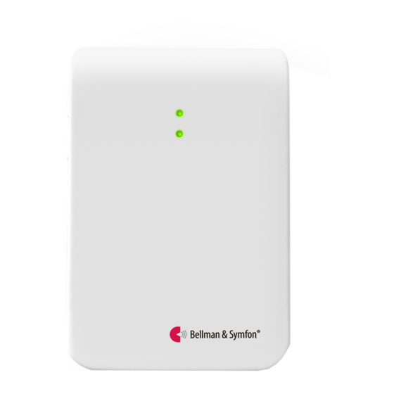
- Seite 8 Advanced testing Default indication and signal Transmitter indication Testing the telephone transmitter is easy. First, make sure that the telephone When the transmitter is activated, the LED lights up in green. This means that transmitter is installed properly. For instructions, read the section Installation. the batteries are in good condition.
- Seite 9 Customizing the signal The telephone transmitter controls the signal pattern on the receiver. Use the signal switches to customize the signal pattern. How to customize the signal pattern Move the signal switches on the Telephone transmitter according to Signal switches Up = On the tables on the following spreads.
- Seite 10 Signal output for 868 MHz and 315 MHz Test button 1 and Mobile phone Test button 1 and Mobile phone Dip switch Output External trigger Dip switch Output External trigger 2 Landline phone sensor 2 Landline phone sensor Light Yellow light Blinking in yellow Green light Light...
- Seite 11 Signal output for 868 MHz and 315 MHz Test button 1 and Mobile phone Test button 1 and Mobile phone Dip switch Output External trigger Dip switch Output External trigger 2 Landline phone sensor 2 Landline phone sensor Light Blinking in yellow Yellow light Green light Light...
- Seite 12 Signal output for 433 MHz Test button 1 and Mobile phone Test button 1 and Mobile phone Dip switch Output External trigger Dip switch Output External trigger 2 Landline phone sensor 2 Landline phone sensor Light Yellow light Yellow light Green light Light Yellow light...
- Seite 13 Signal output for 433 MHz Test button 1 and Mobile phone Test button 1 and Mobile phone Dip switch Output External trigger Dip switch Output External trigger 2 Landline phone sensor 2 Landline phone sensor Light Yellow light Yellow light Green light Light Yellow light...
-
Seite 14: Troubleshooting
Trouble shooting Try this Try this Two orange lights No green light appears • Change batteries. Only use 1.5 V AA (LR6) lithium or • Change batteries. Only use 1.5 V AA (LR6) lithium appear every minute alkaline batteries. on the transmitter when or alkaline batteries. -
Seite 15: Trigger Input
Trigger input Technical information Power supply Battery power: 2 x 1.5 V AA (LR6) lithium or alkaline You can use both stereo and mono plugs. The 3.5 mm input is located on the Power consumption Active < 70 mA, Idle position < 15 μA top right side and the 2.5 mm input under the lid. - Seite 16 (1) this device may not cause Hereby, Bellman & Symfon decla- Use and disposal of batteries interference, and (2) this device res that this Telephone trans- Replace only with the same or equi- must accept any interference, including interference that may mitter is in compliance with valent type recommended by the cause undesired operation of...
- Seite 17 DESIGN FOR EARS ™ bellman.com...