Werbung
Quicklinks
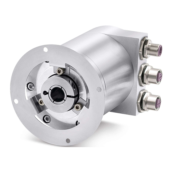
ROTACOD
ATEX absolute fieldbus encoders
Series
EDS file & complete documentation
available for download at www.lika.biz
Warning: encoders having order code ending with "/Sxxx" may have mechanical and electrical characteristics different from standard and be supplied with additional documentation for special connections (Technical Info).
Attenzione: gli encoder con codice di ordinazione finale "/Sxxx" possono avere caratteristiche meccaniche ed elettriche diverse dallo standard ed essere provvisti di documentazione aggiuntiva per cablaggi speciali (Technical info).
Achtung: Geräte, deren Bestellschlüssel mit der Kennung /Sxxx enden, können in ihren mech. und elektr. Eigenschaften vom Standard abweichen. Diese werden daher mit einer ergänzenden Dokumentation ausgeliefert (Technical info).
Atención: los encoders con código de pedido acabado en "/Sxxx" pueden tener características mecánicas y eléctricas diferentes a las básicas y documentación adicional relativa a conexiones especiales (Technical Info).
Attention: les codeurs avec code de commande terminant en "/Sxxx" peuvent avoir des caractéristiques mécaniques et électriques différentes du standard et documentation additionnelle pour les câblages spéciaux (Technical info).
EN
Mounting instructions
Fasten the fixing plate 1 to the encoder using the three M4 screws 2 supplied
with the device;
mount the encoder on the motor shaft using the reducing sleeve (if supplied);
avoid forcing the encoder shaft;
fasten the fixing plate 1 to the rear of the motor using four M4 cylindrical
head screws 3;
fix the collar 4 to the encoder shaft.
ES
Instrucciones de montaje
Fijar la placa de fijación 1 en el encoder mediante los tres tornillos 2 tipo M4
suministrados con el dispositivo;
montar el encoder y el manguito reductor (si se suministra) en el eje del motor
sin forzar el eje del encoder;
fijar la placa de fijación 1 en la parte posterior del motor mediante cuatro
tornillos 3 de cabeza cilíndrica tipo M4;
fijar el collar 4 de el eje del encoder.
M12 4-pin
Description
Pin
Male, A coding
PWR POWER SUPPLY
+10Vdc +30Vdc
1
n.c.
2
0Vdc
3
n.c.
4
M12 4-pin
Description
Pin
Female, D coding
PORT 1, PORT 2
Tx Data +
1
Rx Data +
2
Tx Data -
3
Rx Data -
4
n.c. = not connected
XAC81 EP
IT
Fissare la molla di fissaggio 1 sull'encoder utilizzando le tre viti M4 2 fornite
con il dispositivo;
inserire l'encoder sull'albero del motore utilizzando la boccola di riduzione (se
fornita); evitare sforzi sull'albero encoder;
fissare la molla di fissaggio 1 sul retro del motore utilizzando quattro viti M4 a
testa cilindrica 3;
fissare il collare 4 dell'albero encoder.
FR
Fixer la plaquette de fixation 1 au codeur au moyen des trois vis 2 type M4
fournies avec le dispositif ;
monter le codeur et la douille de réduction (si fournie) sur l'arbre moteur sans
forcer l'arbre du codeur;
fixer la plaquette de fixation 1 à la partie postérieure du moteur en utilisant
quatre vis 3 type M4 à tête cylindrique ;
fixer le collier 4 de l'arbre codeur.
Connector type
frontal side
lato contatti
Aufsicht Stiftseite
lado contactos
côté contacts
Istruzioni di montaggio
Instructions de montage
DIP A = setting the HW / SW EtherNet/IP Node ID
ON = 1, OFF = 0
To access DIP A, remove the
connection cap. Loosen the six
screws 1. Be careful with the
internal
connector.
Always
replace the connection cap at
the end of the operation. Take
care in re-connecting the
internal connector. Tighten the
screws 1 using a tightening
torque of approx. 2.5 Nm.
Check that the encoder
housing and the connection
cap
are
at
the
same
potential before replacing
the connection cap!
Cat. 3 certification, zones 2, 22
Ex II 3G Ex nA IIB T5 Gc
EX II 3D Ex tc IIIC T100° Dc IP65
DE
Montagehinweise
Drehmomentstütze 1 mit den drei beigelieferten M4 Schrauben 2 am Geber
befestigen;
Geber und Reduzierhülse (wenn erforderlich) auf die Motorwelle montieren.
Belastungen der Geberwelle vermeiden;
Drehmomentstütze 1 auf der Rückseite des Motors mit Verwendung für M4
Zylinderschrauben 3 befestigen;
Klemmring 3 festschrauben.
Setting the EtherNet/IP Node ID
DIP A is used to either set the last byte of the hardware IP
address or enable the software IP address. It can further enable
the DHCP protocol. DIP A (default) = 00000000 = software
setting enabled. Default SW Node ID = 192.168.1.10
100 Mbps, full-duplex Ethernet network. EtherNet/IP networks can
be configured in almost any topology in the same structure. Cables
and connectors comply with the Ethernet specifications. The
maximum segment length for electrical data transmission with
copper cables between two nodes is 100 m / 328 ft. The unit can be
identified in the network through the MAC address (10 B9 FEh +
manufacturer consecutive number) and the IP address (see above).
PORT 1 and PORT 2 are interchangeable. EtherNet/IP network needs
no line termination.
Installation has to be carried out with power supply disconnected.
L'installazione deve essere eseguita in assenza di tensione.
Der Anschluss darf nur bei ausgeschalteter Versorgungsspannung erfolgen.
La instalación sólo debe ser efectuada en ausencia total de tensión.
Le montage du dispositif doit être effectué en absence totale de tension.
Werbung

Verwandte Anleitungen für Lika ROTACOD XAC81 EP-Serie


Inhaltszusammenfassung für Lika ROTACOD XAC81 EP-Serie
- Seite 1 EX II 3D Ex tc IIIC T100° Dc IP65 EDS file & complete documentation available for download at www.lika.biz Warning: encoders having order code ending with "/Sxxx" may have mechanical and electrical characteristics different from standard and be supplied with additional documentation for special connections (Technical Info).
- Seite 2 XAC81 18 / - 14 la Société Lika Electronic nie toute responsabilité pour tout dommage ou blessure que l'utilisateur peut encourir à la suite de la non- XAC81 16 / 16384 - 14 observance des normes de sécurité...