Anmelden
Hochladen
Anleitungen
Marken
DAB Anleitungen
Steuergeräte
E.Box BASIC
DAB E.Box BASIC Handbücher
Anleitungen und Benutzerhandbücher für DAB E.Box BASIC. Wir haben
2
DAB E.Box BASIC Anleitungen zum kostenlosen PDF-Download zur Verfügung: Installations- Und Wartungsanleitungen, Sicherheitsanweisungen
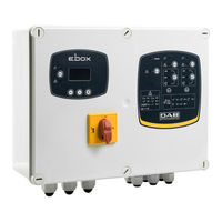
DAB E.Box BASIC Installations- Und Wartungsanleitungen (760 Seiten)
Marke:
DAB
| Kategorie:
Schalttafel
| Dateigröße: 17.33 MB
Inhaltsverzeichnis
Italiano
3
Inhaltsverzeichnis
3
Legenda
8
Avvertenze
8
Responsabilita
8
Caratteristiche Tecniche
9
1 Generalita
8
2 Installazione
9
Tabella 1: Dati Tecnici
9
Protezioni
9
Collegamenti Elettrici
10
2.1.1 Verifiche Strumentali a Carico Dell'installatore
10
2.1.2 Schede E Connessioni
11
Collegamento Elettrico Pompe
13
Collegamento Pompe Trifase
13
Collegamento Pompe Monofase con Condensatore Interno
13
Collegamento Pompe Monofase con Condensatore Esterno
13
Collegamento Elettrico Alimentazione
14
3 Pannello Frontale
15
4 Pannello Interno DI Regolazione Quadro
16
Trimmer DI Regolazione Dell'impianto (Imax - SP - DP)
16
Collegamenti Elettrici Pompa E Alimentazione
17
Dip-Switch DI Selezione Funzioni (DS_A - DS_B)
17
5 Funzione Pressurizzazione
17
Vaso DI Espansione
17
Collegamento Protezioni Supplementari: Alta Pressione, Bassa Pressione E Protezione Termica Motore
18
Collegamento Uscite Allarmi
18
Collegamento Sensore DI Pressione
19
Funzionamento con Pressostati
19
Funzionamento con Sensore Pressione (Scelta Consigliata)
19
Impostazione Tramite Display, Wizard
19
Impostazione con Sensore DI Pressione
20
Configurazione con Pressostati
21
Impostazione E.box Tramite Dip Switch
21
Attivazione del Gruppo
22
Funzionamento del Sistema
22
Pressostati
22
Tabella 2: Funzionamento Pressurizzazione con Pressostati
22
Sensore DI Pressione
23
Regolazione Corrente Nominale Delle Pompe (Imax), Set Point (SP) E Pressione Differenziale DI Ripartenza (DP)
22
6 Funzione Riempimento
23
Tabella 3: Funzionamento Pressurizzazione Vaso Standard
23
Tabella 4: Funzionamento con Vaso DI Espansione Aggiuntivo > 100 Litri
23
Collegamenti Elettrici Pompa E Alimentazione
24
Collegamento Protezioni Supplementari: Troppo Pieno, Mancanza D'acqua, Protezione Termica Motore
24
Ingressi DI Controllo
24
Collegamento Galleggianti O Sonde DI Livello
25
Collegamento Uscite Allarmi
25
Collegamento Sensore DI Profondità
26
Impostazione Tramite Display, Wizard
26
Configurazione Galleggianti O Sonde DI Livello
27
Configurazione con Sensore DI Profondità
28
Attivazione del Gruppo
29
Impostazione E.box Dip Switch
29
Regolazione Corrente Nominale Delle Pompe (Imax) E Livelli DI Avvio E Arresto Delle Pompe (solo con Sensore DI Profondità Collegato)
29
Funzionamento del Sistema
30
Funzionamento con 2 Galleggianti O Sonde DI Livello
30
Funzionamento con 3 Galleggianti O Sonde DI Livello
30
Funzionamento con Sensore DI Profondità E Display
30
Funzionamento con Sensore DI Profondità Senza Display
30
Tabella 5: Riempimento Funzionamento a 2 Galleggianti
30
Tabella 6: Riempimento Funzionamento a 3 Galleggianti
30
Tabella 7: Funzionamento con Sensore DI Profondità, Senza Display
31
Collegamenti Elettrici Pompa E Alimentazione
32
Collegamento Protezioni Supplementari: Troppo Pieno, Mancanza D'acqua, Protezione Termica Motore
32
7 Funzione Svuotamento (Drenaggio)
32
Ingressi DI Controllo
32
Collegamento Uscite Allarmi
33
Collegamento Galleggianti O Sonde DI Livello
34
Collegamento Sensore DI Profondità
34
Impostazione Tramite Display, Wizard
34
Configurazione Galleggianti O Sonde DI Livello
35
Configurazione con Sensore DI Profondità
36
Attivazione del Gruppo
37
Impostazione E.box Tramite Dip Switch
37
Funzionamento del Sistema
38
Funzionamento con 2 Galleggianti O Sonde DI Livello
38
Funzionamento con 3 Galleggianti O Sonde DI Livello
38
Tabella 8: Riempimento Funzionamento a 2 Galleggianti
38
Tabella 9: Riempimento Funzionamento a 3 Galleggianti
38
Funzionamento con Sensore DI Profondità E Display
39
Funzionamento con Sensore DI Profondità Senza Display
39
Regolazione Corrente Nominale Delle Pompe (Imax) E Livelli DI Avvio Ed Arresto Delle Pompe (solo con Sensore DI Profondità Collegato)
38
8 Funzione Pressurizzazione Kiwa
39
Vaso DI Espansione
39
Tabella 10: Drenaggio con Sensore DI Profondità, Senza Display
39
Collegamenti Elettrici Pompa E Alimentazione
40
Collegamento Protezioni Supplementari: Alta Pressione E Protezione Termica Motore
40
Collegamento Uscite Allarmi
40
Funzionamento con Sensore Pressione (Scelta Consigliata)
40
Collegamento Pressostati
41
Collegamento Pressostato Bassa Pressione
41
Collegamento Sensore DI Pressione
41
Funzionamento con Pressostati
41
Impostazione Tramite Display, Wizard
41
Configurazione con Pressostati
42
Impostazione con Sensore DI Pressione
42
Attivazione del Gruppo
43
Impostazione E.box Tramite Dip Switch
43
Stato del Sistema in Modalità Kiwa
43
Funzionamento del Sistema
44
Pressostati
44
Sensore DI Pressione
44
Tabella 11: Funzionamento Pressurizzazione con Pressostati
44
Tabella 13: Funzionamento con Vaso DI Espansione Aggiuntivo > 100 Litri
45
Regolazione Corrente Nominale Delle Pompe (Imax), Set Point (SP) E Pressione Differenziale DI Ripartenza(DP)
44
9 La Tastiera E Il Display
46
Accesso Ai Menù
47
Accesso Diretto con Combinazione DI Tasti
47
Tabella 14: Funzioni Tasti
47
Tabella 15: Accesso Ai Menù
48
Accesso Per Nome Tramite Menù a Tendina
49
Menù
47
Riga DI Stato
47
Significato Dei Singoli Parametri
49
9.4.1 Menù Utente
49
VP: Visualizzazione Della Pressione
49
C1: Visualizzazione Della Corrente DI Fase Della Pompa P1
49
C2: Visualizzazione Della Corrente DI Fase Della Pompa P2
49
PO1: Visualizzazione Della Potenza Assorbita Dalla Pompa P1
49
PO2: Visualizzazione Della Potenza Assorbita Dalla Pompa P2
49
VE: Monitor DI Sistema
49
SN: Serial
49
FF: Visualizzazione Storico Fault
50
CT: Contrasto Display
50
LA: Lingua
50
HS: Ore DI Funzionamento del Sistema
50
H1: Ore DI Funzionamento Della Pompa P1
50
H2: Ore DI Funzionamento Della Pompa P2
50
9.4.3 Menù Setpoint
50
SP: Impostazione Della Pressione DI Set-Point
50
Con Sensore DI Pressione)
50
RP: Impostazione del Differenziale DI Pressione
50
Menù Assistenza Tecnica
51
Menù Installatore
51
Protezioni Ed Allarmi Quadro
52
Tabella 17: Tabella Generale Allarmi: Segnalazioni E Contatti
54
Tabella 18: Protezione/Allarme Proveniente Dagli Ingressi Digitali R E N
54
Tabella 19: Errori E.box Visualizzati a Display
57
Tabella 20: Allarmi RI
58
VS: Errore Selettore DI Tensione
59
Tabella 21: Allarmi ni
59
OM: Cambio Modalità DI Funzionamento
60
Reset E Impostazioni DI Fabbrica
60
Reset Generale del Sistema
60
Ripristino Delle Impostazioni DI Fabbrica
60
English
61
Key
66
Warnings
66
Responsibility
66
1 General
66
Technical Characteristics
67
Protections
67
2 Installation
67
Table 1: Technical Data
67
Electrical Connections
68
Instrumental Checks to be Carried out by the Installer
68
2.1.2 Boards and Connections
69
Figure 1: E.box Basic Board
69
Figure 2: E.box Plus Board
70
Electrical Connection of the Pumps
71
Connection of Single-Phase Pumps with External Capacitor
71
Connection of Single-Phase Pumps with Internal Capacitor
71
Connection of Three-Phase Pumps
71
Figure 3: Electrical Connection of Pumps
71
Power Supply Electrical Connection
72
Figure 4: Connection of Pump External Capacitors
72
Figure 5: Electrical Connection to the Supply Line
72
Figure 6: Display Label, Present Only on Plus Models
73
Figure 7: Front Label
73
3 Front Panel
73
4 Panel Internal Regulating Board
74
Trimmer for Regulating the System (Imax - SP - DP)
74
Standard Regulation in Bars
74
Optional Regulation in Metres (Plate Supplied)
74
Dip-Switch for Selecting Functions (DS_A - DS_B)
75
5 Pressure Boosting Function
75
Expansion Vessel
75
Electrical Connections of Pump and Supply
75
Connection of Additional Protections: High Pressure, Low Pressure and Motor Thermal Protection
76
Connection of the Alarm Outputs
76
Figure 8: Inputs and Outputs
76
Figure 9: Thermal Protection Inputs KK
76
Operation with Pressure Sensor (Recommended Choice)
77
Connection of the Pressure Sensor
77
Operation with Pressure Switches
77
Setting with the Display, Wizard
77
Figure 10: Pressure Sensor Connection 4..20Ma
77
Figure 11: Terminals for Connecting the Pressure Switches
77
Setting with a Pressure Sensor
78
Figure 12: Configuration with a Pressure Sensor
78
Configuration with Pressure Switches
79
Setting the E.box with Dip Switches
79
Figure 13: Configuration with Pressure Switches
79
Figure 14: Dip Switches for Pressure Boosting
79
Activation of the Set
80
Regulating the Rated Current of the Pumps (Imax), Set Point (SP) and Differential Restarting Pressure (DP)
80
System Operation
80
Pressure Switches
80
Table 2: Pressure Boosting Operation with Pressure Switches
80
Figure 15: Enabling P1 and P2
80
Figure 16: Regulating: Imax, SP and DP
80
Pressure Sensor
81
Table 3: Pressure Boosting Operation Standard Vessel
81
Table 4: Operation with Additional Expansion Vessel > 100 Litres
81
Figura 17: Regulation with Expansion Vessel
81
Figura 18: Regulation with Expansion Vessel > 100 Litres
81
6 Filling Function
82
Electrical Connections of Pump and Supply
82
Control Inputs
82
Connection of Additional Protections: Overflow, Water Lack, Motor Thermal Protection
82
Figure 19: Diagram of Filling System Inputs
82
Connection of the Alarm Outputs
83
Figure 20: Inputs and Protections
83
Figure 21: Thermal Protection Inputs KK
83
Connection of Floats or Level Probes
84
Depth Sensor Connection
84
Setting with the Display, Wizard
84
Figure 22: Inputs
84
Figure 23: Depth Sensor Connection
84
Configuration of Floats or Level Probes
85
Figure 24: Configuration of Filling with Floats or Level Probes
85
Figure 25: System Status in Filling Mode, with Floats or Level Probes as Control Inputs
85
Configuration with a Depth Sensor
86
Figure 26: a System Status with Depth Sensor Only, B Depth Sensor and Floats, C Depth Sensor and Level Probes
86
Setting the E.box with Dip Switches
87
Activation of the Set
87
Regulating the Rated Current of the Pumps (Imax) and the Pump Starting and Stopping Levels (Only with Depth Sensor Connected)
87
Figure 27: Setting the Filling Dip Switches
87
Figure 28: Enabling P1 and P2
87
System Operation
88
Operation with 2 Floats or Level Probes
88
Operation with 3 Floats or Level Probes
88
Operation with Depth Sensor and Display
88
Operation with Depth Sensor Without Display
88
Table 5: Filling Operation with 2 Floats
88
Table 6: Filling Operation with 3 Floats
88
Figure 29: Regulating the Rated Current SP and DP
88
Table 7: Operation with Depth Sensor, Without Display
89
Figure 30: Filling with a Depth Sensor
89
7 Draining Function
90
Electrical Connections of Pump and Supply
90
Control Inputs
90
Connection of Additional Protections: Overflow, Water Lack, Motor Thermal Protection
90
Figure 31: Draining System Diagram
90
Connection of the Alarm Outputs
91
Figure 32: Position of Inputs and Alarms
91
Figure 33: Thermal Protection Inputs KK
91
Connection of Floats or Level Probes
92
Depth Sensor Connection
92
Setting with the Display, Wizard
92
Figure 34: Inputs
92
Figure 35: Depth Sensor Connection
92
Configuration of Floats or Level Probes
93
Figure 36: Configuration of Drainage Floats or Level Probes
93
Figure 37: System Status in Drainage Mode, a with Level Probes. B with Floats
93
Configuration with a Depth Sensor
94
Figure 38: Configuration with Only a Depth Sensor
94
Setting the E.box with Dip Switches
95
Activation of the Set
95
Figure 39: System Status in Configurations: a with Only Depth Sensor, B: Depth Sensor and Floats, C Depth Sensor and Level Probes
95
Figure 40: Setting the Drainage Dip Switches
95
Figure 41: Enabling P1 and P2
95
Regulating the Rated Current of the Pumps (Imax) and the Pump Starting and Stopping Levels (Only with Depth Sensor Connected)
96
System Operation
96
Operation with 2 Floats or Level Probes
96
Operation with 3 Floats or Level Probes
96
Operation with Depth Sensor and Display
96
Table 8: Filling Operation with 2 Floats
96
Table 9: Filling Operation with 3 Floats
96
Figure 42: Regulating the Rated Current SP and DP
96
Operation with Depth Sensor Without Display
97
8 Kiwa Pressure Boosting Function
97
Expansion Vessel
97
Electrical Connections of Pump and Supply
97
Connection of Additional Protections: High Pressure and Motor Thermal Protection
97
Table 10: Drainage with Depth Sensor, Without Display
97
Figure 43: Drainage with a Depth Sensor
97
Connection of the Alarm Outputs
98
Operation with Pressure Sensor (Recommended Choice)
98
Connection of the Pressure Sensor
98
Figure 44: Inputs
98
Figure 45: Thermal Protection Inputs KK
98
Operation with Pressure Switches
99
Connection of Pressure Switches
99
Connecting the Low-Pressure Pressure Switch
99
Setting with the Display, Wizard
99
Figure 46: Connection of the Pressure Sensor 4..20Ma
99
Figure 47: Pressure Switch Terminal Board
99
Setting with a Pressure Sensor
100
Configuration with Pressure Switches
100
Figure 48: KIWA Pressure Boosting with Pressure Sensor
100
Figure 49: Kiwa Configuration with Pressure Switches
100
System Status in Kiwa Mode
101
Setting the E.box with Dip Switches
101
Activation of the Set
101
Figure 50: System Status in KIWA Mode
101
Figure 51: Dip Switches for KIWA Pressure Boosting
101
Figure 52: Enabling P1 and P2
101
Regulating the Rated Current of the Pumps (Imax), Set Point (SP) and Differential Restarting Pressure (DP)
102
System Operation
102
Pressure Switches
102
Pressure Sensor
102
Table 11: Pressure Boosting Operation with Pressure Switches
102
Figure 53: Regulating the Rated Current SP and DP
102
Table 12: Pressure Boosting Operation Standard Vessel
103
Table 13: Operation with Additional Expansion Vessel > 100 Litres
103
Figura 54: Regulation with Expansion Vessel
103
Figura 55: Regulation with Expansion Vessel > 100 Litres
103
Figure 56: Label and Keys
104
Status Line
105
Menus
105
Access to the Menus
105
Direct Access with a Combination of Keys
105
Figure 57: Label, Keys and Display
105
Table 14: Key Functions
105
Table 15: Access to the Menus
106
Access by Name with a Drop-Down Menu
107
Meaning of the Individual Parameters
107
9.4.1 User Menu
107
C1: Display of the Phase Current of Pump P1
107
C2: Display of the Phase Current of Pump P2
107
PO1: Display of the Power Absorbed by Pump P1
107
PO2: Display of the Power Absorbed by Pump P2
107
SN: Serial
107
VE: System Monitor
107
VP: Pressure Display
107
9.4.3 Setpoint Menu
108
CT: Display Contrast
108
FF: Fault Log Display
108
H1: Pump P1 Operating Hours
108
H2: Pump P2 Operating Hours
108
HS: System Operating Hours
108
LA: Language
108
Pressure Sensor)
108
RP: Setting the Pressure Differential
108
SP: Setting the Set Point Pressure
108
Technical Assistance Menu
109
AB: Anti-Blocking (Only in Drainage)
110
Table 17: General Table of Alarms: Signals and Contacts
112
Table 18: Digital Inputs R and N Protection /Alarm
112
Voltage Error
114
Table 19: E.box Errors Shown on the Display
115
Table 20: RI Alarms
116
NL: Input Voltage Error
117
Table 21: ni Alarms
117
VS: Voltage Selector Error
117
OM: Changed Operating Mode
118
Reset and Factory Settings
118
General System Reset
118
Restoring the Factory Settings
118
9 The Keypad and the Display
104
Français
119
Avertissements
124
Responsabilités
124
Légende
124
1 Généralités
124
Caractéristiques Techniques
125
Protections
125
2 Installation
125
Branchements Électriques
126
2.1.1 Vérifications Instrumentales à Effectuer Par L'installateur
126
2.1.2 Cartes et Branchements
127
Branchement Électrique des Pompes
129
Branchement des Pompes Triphasées
129
Branchement des Pompes Monophasées à Condensateur Interne
129
Branchement des Pompes Monophasées à Condensateur Externe
129
Branchement Électrique D'alimentation
130
3 Panneau Avant
131
4 Panneau Interne de Réglage du Tableau
132
Trimmer de Réglage de L'installation (Imax - SP - DP)
132
Commutateur DIP de Sélection des Fonctions (DS_A - DS_B)
133
5 Fonction Pressurisation
133
Vase D'expansion
133
Branchements Électriques Pompe et Alimentation
133
Connexion des Protections Supplémentaires : Haute Pression, Basse Pression et Protection Thermique Moteur
134
Branchement Sorties Alarmes
134
Fonctionnement Avec Capteur de Pression (Choix Conseillé)
135
Branchement du Capteur de Pression
135
Fonctionnement Avec les Pressostats
135
Réglage à L'aide de L'écran, Assistant
135
Réglage Avec Capteur de Pression
136
Fonctionnement Avec des Pressostats
137
Réglage de E.box à L'aide du Commutateur DIP
137
Activation du Groupe
138
Réglage du Courant Nominal des Pompes (Imax), Point de Consigne (SP) et Pression Différentielle de Redémarrage (DP)
138
136 5.14 Fonctionnement du Système
138
Pressostats
138
Capteur de Pression
139
6 Fonction Remplissage
139
Branchements Électriques Pompe et Alimentation
140
Entrées de Contrôle
140
Raccord des Protections Supplémentaires : Trop-Plein, Manque D'eau, Protection Thermique du Moteur
140
Branchement Sorties Alarmes
141
Branchement des Flotteurs ou Sondes de Niveau
141
Branchement du Capteur de Profondeur
142
Réglage à L'aide de L'écran, Assistant
142
Configuration des Flotteurs ou Sondes de Niveau
143
Configuration Avec Capteur de Profondeur
144
Réglage de E.box Commutateur DIP
145
Activation du Groupe
145
Réglage du Courant Nominal des Pompes (Imax) et Niveaux de Démarrage et D'arrêt des Pompes (Uniquement Lorsqu'un Capteur de Profondeur Est Branché)
145
Fonctionnement du Système
146
Fonctionnement Avec 2 Flotteurs ou Sondes de Niveau
146
Fonctionnement Avec 3 Flotteurs ou Sondes de Niveau
146
Fonctionnement Avec Capteur de Profondeur et Écran
146
Fonctionnement Avec Capteur de Profondeur Sans Écran
146
7 Fonction de Vidange (Drainage)
148
Branchements Électriques Pompe et Alimentation
148
Entrées de Contrôle
148
Raccord des Protections Supplémentaires : Trop-Plein, Manque D'eau, Protection Thermique du Moteur
148
Branchement Sorties Alarmes
149
Branchement des Flotteurs ou Sondes de Niveau
150
Branchement du Capteur de Profondeur
150
Réglage à L'aide de L'écran, Assistant
150
Configuration des Flotteurs ou Sondes de Niveau
151
Configuration Avec Capteur de Profondeur
152
Réglage de E.box à L'aide du Commutateur DIP
153
Activation du Groupe
153
Les Modifications Suivantes Peuvent Être Apportées à la Configuration
153
Si L'utilisateur Souhaite que les Pompes S'alternent Toutes les 24 Heures et Non Pas à Chaque Redémarrage, Placer DS_A2 Sur on
153
Réglage du Courant Nominal des Pompes (Imax) et Niveaux de Démarrage et D'arrêt des Pompes (Uniquement Lorsqu'un Capteur de Profondeur Est Branché)
154
Fonctionnement du Système
154
Fonctionnement Avec 2 Flotteurs ou Sondes de Niveau
154
Fonctionnement Avec 3 Flotteurs ou Sondes de Niveau
154
Fonctionnement Avec Capteur de Profondeur et Écran
154
Si L'utilisateur Ne Souhaite Pas la Protection Contre les Redémarrages Trop Rapides, Placer DS_A3 Sur off
154
Si L'utilisateur Ne Souhaite Pas Utiliser la Pompe P1, Placer DS_A7 Sur on
154
Si L'utilisateur Ne Souhaite Pas Utiliser la Pompe P2, Placer DS_A8 Sur on
154
Fonctionnement Avec Capteur de Profondeur Sans Écran
155
8 Fonction de Pressurisation Kiwa
155
Vase D'expansion
155
Branchements Électriques Pompe et Alimentation
156
Connexion des Protections Supplémentaires : Haute Pression et Protection Thermique Moteur
156
Branchement Sorties Alarmes
156
Fonctionnement Avec Capteur de Pression (Choix Conseillé)
157
Branchement du Capteur de Pression
157
Fonctionnement Avec les Pressostats
157
Branchement des Pressostats
157
Branchement du Pressostat de Basse Pression
157
Réglage à L'aide de L'écran, Assistant
157
Réglage Avec Capteur de Pression
158
Configuration Avec des Pressostats
158
État du Système en Mode KIWA
159
Réglage de E.box à L'aide du Commutateur DIP
159
Activation du Groupe
159
Réglage du Courant Nominal des Pompes (Imax), Point de Consigne (SP) et Pression Différentielle de Redémarrage (DP)
160
Fonctionnement du Système
160
Pressostats
160
Capteur de Pression
160
9 Le Clavier et L'écran
162
Barre D'état
163
Menu
163
Accès aux Menus
163
Accès Direct Par une Combinaison de Touches
163
Touches D'accès Direct
164
Accès Par le Nom à L'aide du Menu Déroulant
165
Signification des Différents Paramètres
165
9.4.1 Menu Utilisateur
165
VP : Affichage de la Pression
165
C1 : Affichage du Courant de Phase de la Pompe P1
165
C2 : Affichage du Courant de Phase de la Pompe P2
165
PO1 : Affichage de la Puissance Absorbée Par la Pompe P1
165
PO2 : Affichage de la Puissance Absorbée Par la Pompe P2
165
VE : Écran de Système
165
SN: Serial
165
FF : Affichage de L'historique des Pannes
166
CT : Contraste Écran
166
LA : Langue
166
HS : Heures de Fonctionnement du Système
166
H1 : Heures de Fonctionnement de la Pompe P1
166
H2 : Heures de Fonctionnement de la Pompe P2
166
9.4.3 Menu Point de Consigne
166
HC : Niveau de Démarrage Pompe P2 (Uniquement en cas de Drainage ou de Remplissage Avec Capteur de Profondeur)
166
HB : Niveau de Démarrage Pompe P1 (Uniquement en cas de Drainage ou de Remplissage Avec Capteur de Profondeur)
166
HA : Niveau D'arrêt des Pompes (Uniquement en cas de Drainage ou de Remplissage Avec Capteur de Profondeur)
166
RC : Réglage du Courant Nominal de L'électropompe
167
MF : Mode de Fonctionnement
167
MC : Dispositifs de Contrôle
167
GS : Dispositifs de Protection (Uniquement en cas de Drainage ou de Remplissage ou Avec Capteur de Profondeur)
167
PR : Type de Capteur Employé (Uniquement si un Capteur de Pression ou de Profondeur Est Utilisé)
167
MS : Système de Mesure
167
SO : Facteur de Fonctionnement à Sec
167
MP : Seuil Minimum de Pression (Uniquement en cas de Pressurisation et de Pressurisation KIWA)
167
OD : Dimensions du Vase D'expansion (Uniquement en cas de Pressurisation et de Pressurisation KIWA)
167
EP : Exclusion des Pompes
167
ET : Mode Alternance
168
AL : Anti-Fuite
168
AB : Anti-Blocage (Uniquement pour le Drainage)
168
TH : Hauteur Réservoir (Uniquement en Mode Remplissage ou Drainage Avec Capteur de Profondeur)
168
ML : Alarme de Niveau Maximum (Uniquement en Mode Remplissage ou Drainage Avec Capteur de Profondeur)
168
LL : Alarme de Niveau Minimum (Uniquement en Mode Remplissage ou Drainage Avec Capteur de Profondeur)
168
PS: Power Supply System (Modifiable Uniquement Sur EBOX Plus Avec Alimentation de 230V)
168
RF : Réinitialisation des Erreurs et Avertissements
168
PW : Paramétrage du Mot de Passe
168
10 Protections et Alarmes du Tableau
168
Erreurs Signalées Par des del D'alarme et Relais
169
Alarme Relais/Télérupteur
171
Pompe Déconnectée
171
Protection/Alarme Fonctionnement à Sec
171
Protection Démarrages Trop Fréquents
171
Protection/Alarme Surcourant (Protection Ampérométrique)
171
Alarme Capteur de Pression ou Profondeur
171
Alarme Incohérence des Flotteurs Et/Ou des Sondes
171
Alarme Commutateur DIP
171
Alarme Erreur
172
Tension D'entrée
172
Erreur du Sélecteur de Tension
172
Erreur de Tension
172
Erreur Interne
172
Erreur Générale Pompe P1 + P2
172
Alarmes Affichées à L'écran
172
10.3.1 Alarmes Signalées à L'écran
172
JR : Alarme Relais/Télérupteur Collé
173
NC : Pompe Déconnectée
173
BL : Protection/Alarme Fonctionnement à Sec
174
LK : Protection Démarrages Trop Fréquents
174
OC : Protection/Alarme Surcourant (Protection Ampérométrique)
174
RI : Alarmes RI
174
NI : Alarmes ni
174
HL : Alarme de Niveau Maximum
175
LL : Alarme de Niveau Minimum
175
BP1/BP2 : Alarme Capteur de Pression/Capteur de Profondeur
175
FI : Incohérence de L'état des Flotteurs ou des Sondes de Niveau
175
DS : Alarme Commutateur DIP
175
W1 : Trimmer SP
175
W2 : Trimmer DP
175
W3 : Trimmer Imax
175
PK : Erreur Touches
175
Deutsch
177
Legende
182
Hinweise
182
Haftung
182
Bemerkung
182
1 Allgemeines
183
Wo die Schalttafel Installiert werden soll
183
Technische Charakteristiken
183
Schutzeinrichtungen
183
2 Installation
183
VERZEICHNIS der TABELLEN Tabelle 1: Technische Daten
183
Elektroanschlüsse
184
2.1.1 Instrumentale Prüfungen zu Lasten des Installateurs
184
2.1.2 Karten und Anschlüsse
185
Abbildung 1: Karte E.box Basic
185
Abbildung 2: Karte E.box Plus
186
Funktion
186
Elektroanschluss der Pumpen
187
Abbildung 3: Elektroanschlüsse der Pumpen
187
Anschluss der Dreiphasigen Pumpe
187
Anschluss der Einphasigen Pumpen mit Externem Kondensator
187
Anschluss der Einphasigen Pumpen mit Internem Kondensator
187
Elektroanschluss der Versorgung
188
Abbildung 4: Anschluss der Externen Kondensatoren an die Pumpen
188
Abbildung 5: Anschluss an die Versorgungsleitung
188
Abbildung 6: Display-Etikett, nur an den Modellen Plus
189
Abbildung 7: Frontetikett
189
3 Frontpaneel
189
4 Inneres Paneel der Schalttafeleinstellung
190
Trimmer für die Regulierung der Anlage (Imax - SP - DP)
190
DIP-Switch zur Selektion von Funktionen (DS_A - DS_B)
191
5 Druckerhöhungsfunktion
191
Ausdehnungsgefäß
191
Elektroanschluss der Pumpen und Versorgung
192
Anschluss der Zusätzlichen Sicherungen: Hochdruck, Niederdruck und Motorwärmeschutz
192
Anschluss der Alarmausgänge
192
Abbildung 8: Ein- und Ausgänge
192
Abbildung 9: Eingänge Wärmeschutz KK
192
Funktion mit Drucksensor (Empfohlene Wahl)
193
Anschluss des Drucksensors
193
Funktion mit Druckwächtern
193
Einstellung über das Display, Wizard
193
Abbildung 10: Anschluss des Drucksensors 4..20Ma
193
Abbildung 11: Klemmen für den Anschluss der Druckwächter
193
Einstellung mit Drucksensor
194
Abbildung 12: Konfiguration mit Drucksensor
194
Konfiguration mit Druckwächtern
195
Einstellung von E.box Mittels DIP-Switch
195
Abbildung 13: Konfiguration mit Druckwächtern
195
Abbildung 14: DIP-Switch Druckerhöhung
195
Einschalten der Gruppe
196
Regulierung des Nennstroms der Pumpen (Imax), des Sollwerts (SP) und des Differenzdrucks des Neuanlaufs (DP)
196
Funktionsweise des Systems
196
Druckwächter
196
Abbildung 15: Aktivierung von P1 und P2
196
Abbildung 16: Einstellung: Imax, SP und DP
196
Drucksensor
197
Abbildung 17: Einstellung mit Zusätzlichem Ausdehnungsgefäß
197
Abbildung 18: Einstellung mit Zusätzlichem Ausdehnungsgefäß > 100 Liter I
197
Elektroanschluss der Pumpen und Versorgung
198
Steuereingänge
198
Anschluss Zusätzlicher Sicherungen: Überlauf, Wassermangel, Motorwärmeschutz
198
Abbildung 19: Schaltplan der Eingänge Füllsystem
198
Anschluss der Alarmausgänge
199
Anschluss der Schwimmerschalter oder der Standsonde
199
Abbildung 20: Eingänge und Sicherungen
199
Abbildung 21: Eingänge Wärmeschutz KK
199
Anschluss des Tiefensensors
200
Einstellung über das Display, Wizard
200
Abbildung 22: Eingänge
200
Abbildung 23: Anschluss des Tiefensensors
200
Konfiguration der Schwimmerschalter oder der Standsonde
201
Abbildung 24: Füllkonfiguration mit Schwimmerschaltern oder Standsonden
201
Abbildung 25: Status des Systems in Füllmodus mit Eingängen für die Kontrolle von Schwimmerschaltern oder Standsonden
201
Konfiguration mit Tiefensensor
202
Abbildung 26: a Status des Systems mit nur dem Tiefensensor, B Tiefensensor und Schwimmerschalter, C Tiefensensor und Standsonden
202
Einstellung von E.box DIP-Switch
203
Einschalten der Gruppe
203
Einstellung des Nennstroms der Pumpen (Imax) und Stände für Start und Stopp der Pumpen (nur mit Angeschlossenem Tiefensensor)
203
Abbildung 27: Einstellung IP-Switch Füllung
203
Abbildung 28: Aktivierung von P1 und P2
203
Funktionsweise des Systems
204
Abbildung 29: Einstellung des Nennstroms SP und DP
204
Funktion mit 2 Schwimmerschaltern oder Standsonden
204
Funktion mit 3 Schwimmerschaltern oder Standsonden
204
Funktion mit Tiefensensor ohne Display
204
Funktion mit Tiefensensor und Display
204
Abbildung 30: Füllung mit Tiefensensor
205
6 Füllfunktion
197
7 ENTLEERUNGSFUNKTION (Drainage)
206
Elektroanschluss der Pumpen und Versorgung
206
Steuereingänge
206
Anschluss Zusätzlicher Sicherungen: Überlauf, Wassermangel, Motorwärmeschutz
206
Abbildung 31: Drainage Anlagen-Schaltplan
206
Anschluss der Alarmausgänge
207
Abbildung 32: Position Eingänge und Alarme
207
Abbildung 33: Eingänge Wärmeschutz KK
207
Anschluss der Schwimmerschalter oder der Standsonde
208
Anschluss des Tiefensensors
208
Einstellung über das Display, Wizard
208
Abbildung 34: Eingänge
208
Abbildung 35: Anschluss des Tiefensensors
208
Konfiguration der Schwimmerschalter oder der Standsonde
209
Abbildung 36: Drainage Konfiguration der Schwimmerschalter oder der Standsonden
209
Abbildung 37: Status des Systems IM Drainagemodus, a mit Standsonden. B mit Schwimmerschaltern
209
Konfiguration mit Tiefensensor
210
Abbildung 38: Konfiguration mit nur dem Tiefensensor
210
Systemstatus und Anlauf
211
Abbildung 39: Status des Systems in den Konfigurationen: a nur Tiefensensor, B: Tiefensensor und Schwimmerschalter, C Tiefensensor und
211
Einstellung von E.box Mittels DIP-Switch
211
Einschalten der Gruppe
211
Abbildung 40: Einstellung DIP-Switch Drainage
211
Abbildung 41: Aktivierung von P1 und P2
211
Einstellung des Nennstroms der Pumpen (Imax) und Pegel für Start und Stopp der Pumpen (nur mit Angeschlossenem Tiefensensor)
212
Funktionsweise des Systems
212
Funktion mit 2 Schwimmerschaltern oder Standsonden
212
Funktion mit 3 Schwimmerschaltern oder Standsonden
212
Abbildung 42: Einstellung des Nennstroms SP und DP
212
Funktion mit Tiefensensor und Display
213
Funktion mit Tiefensensor ohne Display
213
Abbildung 43: Drainage mit Tiefensensor
213
8 Kiwa Druckerhöhungsfunktion
214
Ausdehnungsgefäß
214
Elektroanschluss der Pumpen und Versorgung
214
Anschluss der Zusätzlichen Sicherungen: Hochdruck und Motorwärmeschutz
214
Abbildung 44: Eingänge
214
Abbildung 45: Eingänge Wärmeschutz KK
214
Anschluss der Alarmausgänge
215
Funktion mit Drucksensor (Empfohlene Wahl)
215
Anschluss des Drucksensors
215
Funktion mit Druckwächtern
215
Anschluss der Druckwächter
215
Anschluss des Niederdruckwächters
215
Abbildung 46: Anschluss des Drucksensors 4..20Ma
215
Abbildung 47: Klemmenbrett der Druckwächter
215
Einstellung über das Display, Wizard
216
Einstellung mit Drucksensor
216
Abbildung 48: KIWA Druckerhöhung mit Drucksensor
216
Konfiguration mit Druckwächtern
217
Systemstatus IM KIWA-Modus
217
Einstellung von E.box Mittels DIP-Switch
217
Abbildung 49: Konfiguration KIWA mit Druckwächtern
217
Abbildung 50: Systemstatus IM KIWA-Modus
217
Abbildung 51: DIP-Switch KIWA Druckerhöhung
217
Einschalten der Gruppe
218
Regulierung des Nennstroms der Pumpen (Imax), des Sollwerts (SP) und des Differenzdrucks des Neuanlaufs (DP)
218
Funktionsweise des Systems
218
Druckwächter
218
Abbildung 52: Aktivierung von P1 und P2
218
Abbildung 53: Einstellung des Nennstroms SP und DP
218
Drucksensor
219
Abbildung 54: Einstellung mit Zusätzlichem Ausdehnungsgefäß
219
Abbildung 55: Einstellung mit Zusätzlichem Ausdehnungsgefäß > 100 Liter
220
Abbildung 56: Etikett und Tasten
220
Statuszeile
221
Menü
221
Zugriff auf das Menü
221
Abbildung 57: Etikett, Tasten und Display
221
Direkter Zugriff mit Tastenkombination
221
Tasten für den Direktzugriff
222
Zugriff nach Namen Mittels Drop-Down-Menü
223
Bedeutung der Einzelnen Parameter
223
9.4.1 Benutzer-Menü
223
C1: Anzeige des Phasenstroms der Pumpe P1
223
C2: Anzeige des Phasenstroms der Pumpe P2
223
PO1: Anzeige der Leistungsaufnahme der Pumpe P1
223
PO2: Anzeige der Leistungsaufnahme der Pumpe P2
223
SN: Serial
223
VE: System-Monitor
223
VP: Anzeige des Drucks
223
9.4.3 Sollwert-Menü
224
CT: Displaykontrast
224
FF: Anzeige der Fehler-Historie
224
H1: Betriebsstunden der Pumpe P1
224
H2: Betriebsstunden der Pumpe P2
224
HS: Betriebsstunden des Systems
224
LA: Sprache
224
Mit Drucksensor)
224
RP: Eingabe des Druckdifferentials
224
SP: Eingabe des Sollwertdrucks
224
EP: Ausschluss der Pumpen
225
GS: Schutzeinrichtung (nur in Drainage oder Füllung oder mit Tiefensensor)
225
MC: Kontrollvorrichtung
225
MF: Funktionsmodi
225
MP: Mindestdruckschwelle (nur in Druckerhöhung und KIWA-Druckerhöhung)
225
MS: Maßsystem
225
OD: Größe des Ausdehnungsgefäßes (nur in Druckerhöhung und KIWA-Druckerhöhung)
225
PR: Typ des Verwendeten Sensors (nur bei Verwendung eines Druck- oder Tiefensensors)
225
RC: Eingabe des Nennstroms der Elektropumpe
225
SO: Trockenlauf-Faktor
225
AB: Blockierschutz (nur in Drainage)
226
AL: Leckageschutz
226
ET: Wechselmodus
226
LL: Alarm für Mindeststand (nur bei Füllung oder Drainage mit Tiefensensor)
226
ML: Alarm für Höchststand (nur bei Füllung oder Drainage mit Tiefensensor)
226
PS: Power Supply System (nur am EBOX Plus mit Stromversorgung 230V Veränderbar)
226
PW: Passwort-Eingabe
226
RF: Nullstellung Fault & Warning
226
TH: Tankhöhe (nur bei Füllung oder Drainage mit Tiefensensor)
226
9 Tastatur und Display
220
10 Schutzeinrichtungen und Alarme der Schalttafel
226
Über Alarm-LED und Relais Gemeldete Fehler
227
Schutzeinrichtung/Alarm von den Digitaleingängen R und N
228
Alarm Relais/Schütz
229
Pumpe Abgehängt
229
Schutzeinrichtung/Trockenlauf-Alarm
229
Schutz gegen zu Häufiges Anlaufen
229
Schutzeinrichtung/Alarm für Überstrom (Überstromschutz)
229
Alarm Druck- oder Tiefensensor
229
Alarm für Fehlenden Zusammenhang zwischen Schwimmerschaltern Und/Oder Sonden
229
Alarm DIP-Switch
229
Fehler-Alarm
230
Eingangsspannung
230
Fehler Spannungs-Wahlschalter
230
Spannungsfehler
230
Interner Fehler
230
Allgemeiner Fehler Pumpe P1 + P2
230
Am Display Angezeigte Alarme
230
JR: Alarm Relais/Schütz Verklebt
231
NC: Pumpe Abgehängt
231
BL: Schutzeinrichtung/Trockenlauf-Alarm
231
LK: Schutz gegen zu Häufiges Anlaufen
232
OC: Schutz/Alarm für Überstrom (Überstromschutz)
232
RI: Alarme RI
232
NI: Alarme ni
232
HL: Alarm für Höchststand
233
LL: Alarm für Mindeststand
233
BP1/BP2: Alarm Druck-/Tiefensensor
233
FI: kein Zusammenhang zwischen Status der Schwimmerschalter oder der Standsonden
233
DS: Alarm DIP-Switch
233
W1: Trimmer SP
233
W2: Trimmer DP
233
W3: Trimmer Imax
233
PK: Fehler Tasten
233
NL: Fehler Eingangsspannung
233
VS: Fehler Spannungs-Wahlschalter
234
OM: Wechsel des Betriebsmodus
234
11 Reset und Werkseinstellungen
234
Allgemeines Reset des Systems
234
Wiederherstellung der Werkseinstellungen
234
Dutch
235
Legenda
240
Waarschuwingen
240
Verantwoordelijkheid
240
1 Algemene Informatie
241
Technische Kenmerken
241
Beschermingen
241
2 Installatie
241
Elektrische Aansluitingen
242
2.1.1 Instrumentele Controles Door de Installateur
242
2.1.2 Kaarten en Aansluitingen
243
Elektrische Verbinding Van de Pompen
245
Verbinding Driefasige Pompen
245
Verbinding Eenfasige Pompen Met Interne Condensator
245
Verbinding Eenfasige Pompen Met Externe Condensator
245
Aansluiting Elektrische Voeding
246
3 Frontpaneel
247
4 Intern Regelpaneel Van Het Paneel
248
Regeltrimmer Van de Installatie (Imax - SP - DP)
248
Dipswitches Voor Selectie Van Functies (DS_A - DS_B)
249
5 Drukopbouwfunctie
249
Expansievat
249
Elektrische Aansluitingen Van de Pomp en de Voeding
249
Werking als Afvoergroep
249
Aansluiting Van Aanvullende Beveiligingen. Hoge Druk, Lage Druk en Thermische Motorbeveiliging
250
Aansluiting Alarmuitgangen
250
Werking Met Druksensor (Aanbevolen Keuze)
251
Aansluiting Druksensor
251
Werking Met Drukschakelaars
251
Instelling Via Het Display, Wizard
251
Instelling Met Druksensor
252
Configuratie Met Drukschakelaars
253
Instelling Van E.box Met Dipswitches
253
Activering Van de Groep
254
Regeling Van de Nominale Stroom Van de Pompen (Imax), Setpoint (SP) en Verschildruk Voor Herstart (DP)
254
Werking Van Het Systeem
254
Drukschakelaars
254
Druksensor
255
6 Vulfunctie
255
Elektrische Aansluitingen Van de Pomp en de Voeding
256
Controle-Ingangen
256
Aansluiting Van Aanvullende Beveiligingen: Overloop, Gebrek Aan Water, Thermische Motorbeveiliging
256
Aansluiting Alarmuitgangen
257
Aansluiting Van Vlotters of Niveauvoelers
257
Aansluiting Dieptesensor
258
Instelling Via Het Display, Wizard
258
Configuratie Van Vlotters of Niveauvoelers
259
Configuratie Met Dieptesensor
260
Instelling Van E.box Dipswitches
261
Activering Van de Groep
261
Regeling Van de Nominale Stroom Van de Pompen (Imax) en de Start- en Stopniveaus Van de Pompen (Alleen Met Dieptesensor Aangesloten)
261
Werking Van Het Systeem
262
Werking Met 2 Vlotters of Niveauvoelers
262
Werking Met 3 Vlotters of Niveauvoelers
262
Werking Met Dieptesensor en Display
262
Werking Met Dieptesensor Zonder Display
262
7 Afvoerfunctie (Ontwatering)
264
Elektrische Aansluitingen Van de Pomp en de Voeding
264
Controle-Ingangen
264
Aansluiting Van Aanvullende Beveiligingen: Overloop, Gebrek Aan Water, Thermische Motorbeveiliging
264
Aansluiting Alarmuitgangen
265
Afbeelding 33: Ingangen Thermische Beveiliging KK
265
Aansluiting Van Vlotters of Niveauvoelers
266
Aansluiting Dieptesensor
266
Afbeelding 34: Ingangen
266
Afbeelding 35: Aansluiting Dieptesensor
266
Instelling Via Het Display, Wizard
267
Configuratie Van Vlotters of Niveauvoelers
267
Afbeelding 36: Configuratie Ontwatering Met Vlotters of Niveauvoelers
267
Afbeelding 37: Status Van Het Systeem in de Ontwateringsmodus a Met Niveauvoelers. B Met Vlotters
267
Configuratie Met Dieptesensor
268
Afbeelding 38: Configuratie Met Alleen Dieptesensor
268
Instelling Van E.box Met Dipswitches
269
Activering Van de Groep
269
Afbeelding 39: Staat Van Het Systeem in de Configuraties: a Alleen Met Een Dieptesensor, B Dieptesensor en Vlotters, C Dieptesensor en Niveauvoelers
269
Afbeelding 40: Instelling Dipswitches Voor Ontwatering
269
Afbeelding 41: Inschakeling P1 en P2
269
Regeling Van de Nominale Stroom Van de Pompen (Imax) en de Start- en Stopniveaus Van de Pompen (Alleen Met Dieptesensor Aangesloten)
270
Werking Van Het Systeem
270
Werking Met 2 Vlotters of Niveauvoelers
270
Werking Met 3 Vlotters of Niveauvoelers
270
Werking Met Dieptesensor en Display
270
Afbeelding 42: Regeling Nominale Stroom SP en DP
270
Werking Met Dieptesensor Zonder Display
271
8 Drukopbouwfunctie Kiwa
271
Expansievat
271
Afbeelding 43: Ontwatering Met Dieptesensor
271
Elektrische Aansluitingen Van de Pomp en de Voeding
272
Verbinding Van Aanvullende Beveiligingen: Hoge Druk en Thermische Motorbeveiliging
272
Aansluiting Alarmuitgangen
272
Afbeelding 44: Ingangen
272
Afbeelding 45: Ingangen Thermische Beveiliging KK
272
Werking Met Druksensor (Aanbevolen Keuze)
273
Aansluiting Druksensor
273
Werking Met Drukschakelaars
273
Aansluiting Drukschakelaars
273
Verbinding Drukschakelaar Lage Druk
273
Instelling Via Het Display, Wizard
273
Afbeelding 46: Aansluiting Druksensor 4
273
Afbeelding 47: Klemmenbord Drukschakelaars
273
Instelling Met Druksensor
274
Afbeelding 48: Drukopbouw KIWA Met Druksensor
274
Configuratie Met Drukschakelaar
275
Systeemstatus in Kiwa-Modus
275
Instelling Van E.box Met Dipswitches
275
Afbeelding 49: Configuratie Met Kiwa-Drukschakelaars
275
Afbeelding 50: Systeemstatus in KIWA-Modus
275
Afbeelding 51: Dipswitches Voor KIWA Drukopbouw
275
Activering Van de Groep
276
Regeling Van de Nominale Stroom Van de Pompen (Imax), Setpoint (SP) en Verschildruk Voor Herstart (DP)
276
Werking Van Het Systeem
276
Drukschakelaars
276
Afbeelding 52: Inschakeling P1 en P2
276
Afbeelding 53: Regeling Nominale Stroom SP en DP
276
Druksensor
277
Afbeelding 54: Regeling Met Expansievat Afbeelding 55: Regeling Met Expansievat > 100 Liter
278
Afbeelding 56: Etiket en Toetsen
278
Statusregel
279
Menu's
279
Toegang Tot de Menu's
279
Afbeelding 57: Etiket Toetsen en Display
279
Rechtstreekse Toegang Met Toetsencombinaties
279
Toegang Met Naam Via Vervolgkeuzemenu's
281
Betekenis Van de Afzonderlijke Parameters
281
9.4.1 Gebruikersmenu
281
C1: Weergave Van de Fasestroom Van Pomp P1
281
C2: Weergave Van de Fasestroom Van Pomp P2
281
PO1: Weergave Van Het Vermogen Dat Wordt Opgenomen Door Pomp P1
281
PO2: Weergave Van Het Vermogen Dat Wordt Opgenomen Door Pomp P2
281
SN: Serial
281
VE: Systeemmonitor
281
VP: Drukweergave
281
9.4.3 Menu Setpoint
282
CT: Schermcontrast
282
FF: Weergave Van de Foutengeschiedenis
282
H1: Bedrijfsuren Van de Pomp P1
282
H2: Bedrijfsuren Van de Pomp P2
282
HC: Startniveau Pomp P2 (Alleen Bij Ontwatering of Vullen Met Dieptesensor)
282
HS: Bedrijfsuren Van Het Systeem
282
LA: Taal
282
RP: Instelling Van Het Drukverschil (Alleen Bij Drukopbouw en KIWA Drukopbouw Met Druksensor)
282
SP: Instelling Van de Setpoint-Druk(Alleen Bij Drukopbouw of KIWA Drukopbouw Met Druksensor)
282
EP: Uitsluiting Pompen
283
GS: Beveiligingen (Alleen Bij Ontwatering of Vullen Met Dieptesensor)
283
MC: Controle-Apparaten
283
MF: Bedrijfswijze
283
MP: Minimum Drukgrens (Alleen Bij Drukopbouw of KIWA Drukopbouw)
283
MS: Matenstelsel
283
OD: Maat Expansievat (Alleen Bij Drukopbouw of KIWA Drukopbouw)
283
PR: Gebruikt Type Sensor (Alleen Indien er Een Druk- of Dieptesensor Wordt Gebruikt)
283
RC: Instelling Van de Nominale Stroom Van de Elektropomp
283
SO: Droogbedrijffactor
283
AB: Anti Blokkering (Alleen Bij Ontwatering)
284
AL: Anti-Lekkage
284
ET: Afwisselmodus
284
LL: Alarm Wegens Minimumniveau (Alleen Bij Vullen of Ontwatering Met Dieptesensor)
284
ML: Alarm Wegens Maximum Niveau (Alleen Bij Vullen of Ontwatering Met Dieptesensor)
284
PS: Power Supply System (Alleen Wijzigbaar Op EBOX Plus Met 230 V Voeding)
284
PW: Instelling Wachtwoord
284
RF: Reset Fault en Warning
284
TH: Hoogte Van de Tank (Alleen Bij Vullen of Ontwatering Met Dieptesensor)
284
9 Het Toetsenbord en Het Display
278
10 Beveiligingen en Alarmen Van Het Paneel
284
Fouten Gesignaleerd Via Alarmleds en Relais
285
Beveiliging/Alarm Afkomstig Van de Digitale Ingangen R en N
286
Alarm Relais/Contactgever
287
Pomp Afgekoppeld
287
Beveiliging/Alarm Droogbedrijf
287
Beveiliging Tegen te Veel Starts
287
Beveiliging/Alarm te Hoge Stroom (Stroomopnamebeveiliging)
287
Alarm Druk- of Dieptesensor
287
Alarm Incoherentie Vlotters En/Of Voelers
287
Alarm Dipswitches
287
Alarm Wegens Fout
288
Ingangsspanning
288
Fout Spanningskeuzeschakelaar
288
Spanningsfout
288
Interne Fout
288
Algemene Fout Pomp P1 + P2
288
Op Het Display Weergegeven Alarmen
288
10.3.1 Op Het Display Gesignaleerde Alarmen
288
JR: Alarm Relais/Contactgever Zit Vast
289
NC: Pomp Afgekoppeld
289
BL: Beveiliging/Alarm Droogbedrijf
289
LK: Beveiliging Tegen te Veelvuldige Starts
290
OC: Beveiliging/Alarm Wegens te Hoge Stroom (Stroomopnamebeveiliging)
290
RI: RI-Alarmen
290
NI: NI-Alarmen
290
HL: Alarm Wegens Maximumniveau
291
LL: Alarm Wegens Minimumniveau
291
BP1/BP2: Alarm Druksensor/Dieptesensor
291
FI: Incoherentie Staat Van Vlotters of Niveauvoelers
291
DS: Alarm Dipswitches
291
W1: Trimmer SP
291
W2: Trimmer DP
291
W3: Trimmer Imax
291
PK: Fout Toetsen
291
NL: Fout Ingangsspanning
291
VS: Fout Spanningskeuzeschakelaar
292
Reset en Fabrieksinstellingen
292
Werbung
DAB E.Box BASIC Sicherheitsanweisungen (68 Seiten)
Marke:
DAB
| Kategorie:
Steuergeräte
| Dateigröße: 1.1 MB
Inhaltsverzeichnis
Installazione
5
Collegamenti Elettrici
6
Installation
10
Electrical Connections
11
Branchements Électriques
15
Elektroanschlüsse
20
Inneres Paneel der Schalttafelein- Stellung
22
Einschalten der Gruppe
22
Elektrische Aansluitingen
25
Instalación
29
Conexiones Eléctricas
30
Условные Обозначения
33
Conexiuni Electrice
44
Podłączenia Elektryczne
48
Ηλεκτρικη Συνδεσμολογια
53
Elektromos Bekötések
58
Elektrické Zapojení
63
Werbung
Verwandte Produkte
DAB ESC plus Serie
DAB ESC plus 3M
DAB E2D
DAB E.Box Plus
DAB E.Box Plus D
DAB E.Box Basic D
DAB 2 EURO 30/80 T
DAB E2D 2,6 M
DAB ACTIVE E 40/306
DAB EEG30 T3 S
DAB Kategorien
Pumpen
Wechselrichter
Sanitärtechnik
Radios
Frequenzumrichter
Weitere DAB Anleitungen
Anmelden
Anmelden
ODER
Mit Facebook anmelden
Mit Google anmelden
Anleitung hochladen
Von PC hochladen
Von URL hochladen