Bosch RTM 430 Handbücher
Anleitungen und Benutzerhandbücher für Bosch RTM 430. Wir haben 3 Bosch RTM 430 Anleitungen zum kostenlosen PDF-Download zur Verfügung: Instandsetzungsanweisung, Produktbeschreibung
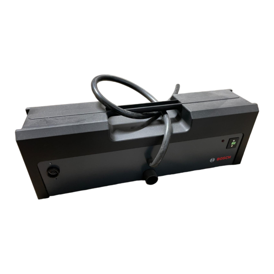
Bosch RTM 430 Produktbeschreibung (48 Seiten)
Marke: Bosch
|
Kategorie: Messgeräte
| Dateigröße: 1 MB
Inhaltsverzeichnis

