Werbung
Quicklinks
Werbung

Verwandte Anleitungen für HEIDENHAIN ERA 180


Inhaltszusammenfassung für HEIDENHAIN ERA 180
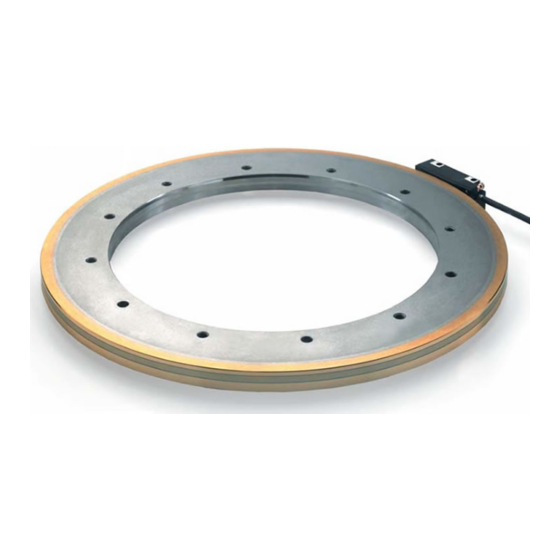
- Seite 1 Mounting Instructions Istruzioni di montaggio ERA 180 ID 639951-xx AK ERA 180 ID 639952-xx 10/2015...
- Seite 2 Inhalt . Contents . Sommaire . Indice . Indice 4, 6 3, 5, 7 Warnings Avvertenze 8, 10, 12 9, 11, 13 Dimensions Dimensioni 14, 16 15, 17 Assembly Montaggio Electrical data and technical specifications Dati elettrici e tecnici 18, 20, 22 19, 20, 22...
- Seite 3 Warnhinweise . Warnings . Recommandations . Avvertenze . Advertencias Achtung: Note: Mounting and commissioning is to be conducted by a qualified specialist under compliance with local safety regulations. Do not engage or disengage any connections while under power. The system must be disconnected from power. Attention: Attenzione: Il montaggio e la messa in funzione devono essere eseguite da personale qualificato nel rispetto delle norme di sicurezza locali.
- Seite 4 Warnhinweise . Warnings . Recommandations . Avvertenze . Advertencias Vorsicht: Caution: Attention: Attenzione: Atención:...
- Seite 5 Achtung: Caution: The specified shaft tolerances must be complied with. The grating drum is to be fastened with all provided screws and washers. The screws must be tightened alternatingly (crosswise) with the tightening torque, and secured against unintentional loosening. Attention: Attenzione: Le tolleranze di montaggio devono essere rispettate.
- Seite 6 Warnhinweise . Warnings . Recommandations . Avvertenze . Advertencias...
- Seite 7 Avoid direct contact of fluids with the encoder and connector! Evitare che lo strumento di misura e il connettore vengano a contatto con liquidi...
- Seite 8 Kundenseitige Anschlussmaße · Required mating dimensions · Conditions requises pour le montage ¬ À ¬ À ¬...
- Seite 9 Dimensioni di collegamento lato cliente · Cotas de montaje requeridas À = Montageabstand mit Folie eingestellt Mounting clearance set with spacer foil Verificata distanza di montaggio con spessimetro Bearing Reference mark centered between marks (approx. ± 2 mm) Shaft tolerance Indice di riferimento al centro rispetto alla marcatura (ca.
- Seite 10 Abmessungen Teilungstrommel · Dimensions Scale Drum · Dimensions Tambour gradué D1 = 120 mm, 180 mm ¬...
- Seite 11 Dimensioni Tamburo · Dimensiones Tambor graduado D1 = 270 mm Mounting face Superfice di montaggio Á  Mounting hole Á ¬ Fori di fissaggio D1 = 425 mm  Back-off thread Filettatura  Á ¬ ¬ 120 ¬ 1401 ¬ 1621 ¬...
-
Seite 12: Abmessungen
Abmessungen · Dimensions · Dimensions Sperrluftabdeckung Protective cover Capot de protection ¬... - Seite 13 Dimensioni · Dimensiones Coperchio protettivo Tapa protectora Mounting face Mounting face Superfice di montaggio Superfice di montaggio ¬ 120 ¬ 180.4 ¬ ¬ 210 ¬ 180 ¬ 250.4 ¬ ¬ 280 ¬ 270 ¬ 425 ¬ 512...
- Seite 14 Montage · Assembly · Montage · Montaggio · Montaje...
- Seite 16 Montage · Assembly · Montage · Montaggio · Montaje "Abtastkopf" Place the spacer foil text "scanning head" in the mounting area of the scanning head "tête captrice" Posizionare la parte di spessimetro con la scritta "unità di scansione" nella zona di montaggio della testina "cabezal"...
- Seite 17 Place overlapped spacer foil in the mounting area of the protective cover Posizionare spessimetro sovrapposto nella zona di montaggio del coperchio protettivo Spacer foil Dima di montaggio...
- Seite 18 Technische Kennwerte . Specifications . Caractéristiques techniques . Dati tecnici . Datos técnicos DA 400 Air purity class 1/4/1 as per ISO 8573-1: 2010 Classe unità aria 1/4/1 a norma ISO 8573-1: 2010 IP 40 IP 00...
- Seite 19 (°C (°F) Ø ‡ ‡ R 1 ‡ 10 mm R 2 ‡ 50 mm Ø 4.5 mm Ø 8 mm R 1 ‡ 40 mm R 2 ‡ 100 mm...
- Seite 20 Elektrische Kennwerte . Electrical Data . Caractéristiques électriques . Dati elettrici . Catacterísticas eléctricas : DC 5 V at encoder, integrato, Without load, senza carico, A, B, R £ £...
- Seite 21 † 150 m »...
- Seite 22 Elektrische Kennwerte . Electrical Data . Caractéristiques électriques . Dati elettrici . Catacterísticas eléctricas External shield connected to housing Schermo del cavo collegato alla carcassa Sensor Sensor A– B– R– > 100 mm > 100 mm > 200 mm Noise sources Sorgenti didisturbo...
- Seite 23 Sollwert: < 1 W max. Check the resistance between the connector housing and the machine. Desired value: < 1 W max. Valeur nominale: < 1 W max. Controllare la resistenza elettrica tra l’alloggiamento del connettore e la macchina. Valore nominale: < 1 W max. Valor nominal: <...
- Seite 24 DR. JOHANNES HEIDENHAIN GmbH 83301 Traunreut, Germany Technical support Measuring systems { TNC support NC programming PLC programming { Lathe controls www.heidenhain.de *I_669523-91*...