Herunterladen Inhalt Inhalt Diese Seite drucken
tecalor FEZ Bedienungsanleitung

tecalor FEZ Bedienungsanleitung

Fernbedienung mit schaltuhr

Werbung

Verfügbare Sprachen
  • DE

Verfügbare Sprachen

  • DEUTSCH, seite 1
BEDIENUNG UND INSTALLATION
OPERATION AND INSTALLATION
UTILISATION ET INSTALLATION
USO E INSTALLAZIONE
OBSLUHA A INSTALACE
OBSŁUGA I INSTALACJA
Fernbedienung für Lüftungsgeräte | Remote control for ventilation units | Commande à distance pour appareils de ventilation
| Telecomando per unità centrali di ventilazione | Dálkové ovládání pro ventilační zařízení | Pilot dla urządzeń wentylacyjnych
» FEZ
12
1
11
2
10
3
9
8
4
5
7
6

Werbung

Inhaltsverzeichnis
loading

Inhaltszusammenfassung für tecalor FEZ

  • Seite 1 OBSŁUGA I INSTALACJA Fernbedienung für Lüftungsgeräte | Remote control for ventilation units | Commande à distance pour appareils de ventilation | Telecomando per unità centrali di ventilazione | Dálkové ovládání pro ventilační zařízení | Pilot dla urządzeń wentylacyjnych » FEZ...
  • Seite 2: Bedienung

    BEDIENUNG ALLGEmEINE HINwEISE BEDIENUNG Symbol Bedeutung Sachschaden (Geräte-, Folge-, Umweltschaden) Geräteentsorgung 1. Allgemeine Hinweise Das Kapitel „Bedienung“ richtet sich an den Gerätebenutzer f Dieses Symbol zeigt Ihnen, dass Sie etwas tun müssen. und den Fachhandwerker. Die erforderlichen Handlungen werden Schritt für Schritt Das Kapitel „Installation“...
  • Seite 3: Gerätebeschreibung

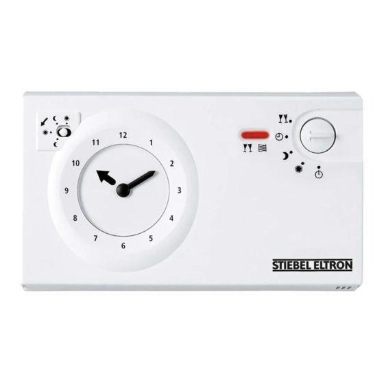
    BEDIENUNG GERäTEBESCHREIBUNG 3. Gerätebeschreibung Betriebsartenschalter Dem Betriebsartenschalter sind fünf Funktionen zugeordnet: Das Gerät dient zur Lüfterstufensteuerung des angeschlosse- nen Lüftungsgerätes. Das Gerät verfügt über eine Tageszeit- Partybetrieb Lüfterstufe 3 schaltuhr sowie Kontrollleuchten für Partybetrieb und Filter- Tagbetrieb Lüfterstufe 2 wechsel. Nachtbetrieb Lüfterstufe 1 Standbybetrieb Das Lüftungsgerät befindet sich im Bereit- schaftsmodus.
  • Seite 4: Wartung

    BEDIENUNG | INSTALLATION wARTUNG INSTALLATION 5. Wartung Filterwechsel Ist ein Filterwechsel im Lüftungsgerät erforderlich, wird dies 6. Sicherheit durch eine Kontrollleuchte angezeigt. Die Installation, Inbetriebnahme sowie wartung und Reparatur Hinweis des Gerätes darf nur von einem Fachhandwerker durchgeführt Der vom Gerät signalisierte Zeitpunkt für den Filter- werden wechsel dient als Richtwert und kann vom tatsächli- chen Verschmutzungsgrad des Filters abweichen.
  • Seite 5: Elektrischer Anschluss

    INSTALLATION INBETRIEBNAHmE 8.2 Elektrischer Anschluss Klemmenbelegung P (0 V) 24-48 V Standby Party f Führen Sie den elektrischen Anschluss entsprechend der obenstehenden Abbildung durch. Beachten Sie dabei die Klemmenbelegung. 1 Arretierschraube in Horizontalstellung verriegelt f Platzieren Sie das Anschlusskabel fachgerecht im Sockel. f Setzen Sie die Frontabdeckung auf den Sockel auf.
  • Seite 6: Außerbetriebnahme

    Die Spannungsversorgung des Gerätes erfolgt durch die elektrische Verbindungsleitung zum Lüftungsge- rät. f Unterbrechen Sie die Spannungsversorgung. 10.1 Wiederinbetriebnahme Siehe Kapitel „Inbetriebnahme / Erstinbetriebnahme“ 11. Technische Daten Fernbedienung FEZ 185358 Elektrische Daten DC-Spannung min. DC-Spannung max. Nennstrom Ausführungen Gangreserve der Uhr 48 h Gehäuse...
  • Seite 7: Kundendienst Und Garantie

    KUNDENDIENST UND GARANTIE Erreichbarkeit Soweit eine Garantieleistung erbracht wird, übernehmen wir Sollte einmal eine Störung an einem unserer Produkte auftreten, keine Haftung für die Beschädigung eines Gerätes durch Dieb- stehen wir Ihnen natürlich mit Rat und Tat zur Seite. stahl, Feuer, Aufruhr oder ähnliche Ursachen. Rufen Sie uns an: Über die vorstehend zugesagten Garantie leistungen hinausgehend 05531 702-111...
  • Seite 8: Umwelt Und Recycling

    UMWELT UND RECYCLING Entsorgung von Transport- und Verkaufsverpackungsmaterial Damit Ihr Gerät unbeschädigt bei Ihnen ankommt, haben wir es sorgfältig verpackt. Bitte helfen Sie, die Umwelt zu schützen, und entsorgen Sie das Verpackungsmaterial des Gerätes sach- gerecht. Wir beteiligen uns gemeinsam mit dem Großhandel und dem Fachhandwerk / Fachhandel in Deutschland an einem wirksamen Rücknahme- und Entsorgungskonzept für die um- weltschonende Aufarbeitung der Verpackungen.
  • Seite 9: Operation

    OPERATION GENERAL INFORmATION OPERATION Symbol Meaning material damage (Appliance and consequential losses, environmental pollution) Appliance disposal 1. General information The chapter "Operation" is intended for appliance users and f This symbol indicates that you have to do something. The heating contractors. action you need to take is described step by step.
  • Seite 10: Appliance Description

    OPERATION APPLIANCE DESCRIPTION 3. Appliance description Operating mode switch Five functions are assigned to the operating mode switch: This device is intended to control the fan stages of the con- nected ventilation unit. The device is equipped with a day time Party mode Fan stage 3 switch as well as indicators for party mode and filter change.
  • Seite 11: Maintenance

    OPERATION | INSTALLATION mAINTENANCE INSTALLATION 5. Maintenance Filter change An indicator illuminates when the filter in the ventilation unit 6. Safety needs changing. Only a qualified contractor should carry out installation, com- Note missioning, maintenance and repair of the appliance. The timing for a filter change signalled by the appli- ance is a guideline only and may not reflect the actual General safety instructions...
  • Seite 12: Installation Commissioning

    INSTALLATION COmmISSIONING Wall mounting 8.2 Power supply The device is suitable for mounting on a surface box or on any level surface. Material damage f when drilling fixing holes, check for the possible presence of cables that may run underneath the plaster.
  • Seite 13: Shutting Down

    The device is supplied with power via the connecting cable that links it to the ventilation unit. f Interrupt the power supply. 10.1 Recommissioning See chapter "Commissioning". 11. Specification Remote control FEZ 185358 Electrical data min. DC voltage max. DC voltage Rated current...
  • Seite 14: Warranty | Environment And Recycling

    WARRANTY | ENVIRONMENT AND RECYCLING Warranty The warranty conditions of our German companies do not apply to appliances acquired outside of Germany. In countries where our subsidiaries sell our products, it is increasingly the case that warranties can only be issued by those subsidiaries. Such warranties are only granted if the subsidiary has issued its own terms of warranty.
  • Seite 15: Remarques Générales

    UTILISATION REmARqUES GéNéRALES UTILISATION Symbole Signification Dommages matériels (dégâts induits, dommages causés à l’appareil, à l’envi- ronnement) Recyclage de l’appareil 1. Remarques générales Le chapitre « Utilisation » s’adresse aux utilisateurs de l’appareil f Ce symbole indique une action à entreprendre. Les ac- et aux installateurs.
  • Seite 16: Description De L'appareil

    UTILISATION DESCRIPTION DE L’APPAREIL 3. Description de l’appareil Sélecteur du mode de fonctionnement Le sélecteur de mode de fonctionnement permet de choisir Cet appareil est destiné à commander la vitesse de ventilation entre cinq modes : de l’appareil de ventilation auquel il est raccordé. L’appareil est équipé...
  • Seite 17 UTILISATION | INSTALLATION mAINTENANCE INSTALLATION 5. Maintenance Changement de filtre S’il devient nécessaire de changer le filtre de l’appareil de ven- 6. Sécurité tilation, le témoin lumineux correspondant s’allume. Le montage, la mise en service, la maintenance et les répara- Remarque tions de cet équipement ne doivent être effectuées que par Le rappel de changement de filtre signalé...
  • Seite 18: Installation Mise En Service

    INSTALLATION mISE EN SERVICE 8.2 Raccordement électrique Bornier P (0 V) De 24 à 48 V Stand-by Dérogation Confort f Effectuez le raccordement électrique comme indiqué sur l’illustration ci-dessus. Veillez à respecter l’affectation des bornes ! 1 Vis d’arrêt verrouillée en position horizontale f Placez le câble de raccordement dans le socle selon les règles de l’art.
  • Seite 19: Données Techniques

    GARANTIE | ENVIRONNEMENT ET RECYCLAGE 11. Données techniques Commande à distance FEZ 185358 Données électriques Tension CC mini Tension CC maxi Courant nominal Versions Réserve de marche de 48 h l’horloge Boîtier Boîtier plastique avec socle enfichable Couleur blanc Indice de protection (IP)
  • Seite 20: Avvertenze Generali

    AVVERTENZE GENERALI Simbolo Significato Danni materiali (danni all'apparecchio, danni conseguenti e danni am- bientali) Smaltimento dell'apparecchio 1. Avvertenze generali Il capitolo "Uso" si rivolge all'utilizzatore finale e al tecnico spe- f questo simbolo indica che si deve intervenire. Le opera- cializzato.
  • Seite 21: Descrizione Dell'apparecchio

    DESCRIZIONE DELL'APPARECCHIO 3. Descrizione dell'apparecchio Selettore modalità di funzionamento Il selettore delle modalità di funzionamento dispone di cinque L'apparecchio serve per il controllo degli stadi ventilatore funzioni: dell'unità di ventilazione collegata. L'apparecchio dispone di un timer giornaliero e di spie di controllo per la modalità di modalità...
  • Seite 22: Manutenzione

    USO | INSTALLAZIONE mANUTENZIONE INSTALLAZIONE 5. Manutenzione Sostituzione del filtro Una spia di controllo segnala quando è necessario sostituire il 6. Sicurezza filtro nell'unità di ventilazione. L'installazione, la messa in funzione, la manutenzione e le ripa- Avvertenza razioni devono essere eseguite esclusivamente da un tecnico Il momento segnalato dall'apparecchio per la sosti- specializzato tuzione del filtro è...
  • Seite 23: Installazione Messa In Funzione

    INSTALLAZIONE mESSA IN FUNZIONE 8.2 Allacciamento elettrico Disposizione dei morsetti P (0 V) 24-48 V Standby Party Giorno f Eseguire il collegamento elettrico come illustrato nella fi- gura di cui sopra. Rispettare le assegnazioni dei morsetti. f Posizionare il cavo di collegamento correttamente all'in- 1 Vite di bloccaggio bloccata in posizione orizzontale terno della base.
  • Seite 24: Spegnimento Del Sistema

    Staccare l'alimentazione. 10.1 Nuova accensione Fare riferimento al capitolo "messa in funzione/Prima messa in esercizio" 11. Dati tecnici Telecomando FEZ 185358 Dati elettrici Tensione CC min. Tensione CC max. Corrente nominale Versioni...
  • Seite 25: Obsluha Všeobecné Pokyny

    OBSLUHA VšEOBECNé POKYNY OBSLUHA Symbol Význam Věcné škody (poškození přístroje, následné škody, poškození životní- ho prostředí) Likvidace přístroje 1. Všeobecné pokyny Kapitola „Obsluha“ je určena uživatelům přístroje a instalačním f Tento symbol vás vyzývá k určitému jednání. Potřebné technikům. úkony jsou popsány po jednotlivých krocích. Kapitola „Instalace“...
  • Seite 26: Popis Přístroje

    OBSLUHA POPIS PřÍSTROJE 3. Popis přístroje přepínač provozních režimů Přepínač provozních režimů má pět přiřazených funkcí: Přístroj slouží ke spínání stupňů ventilátoru připojeného ven- tilačního zařízení. Přístroj je vybaven denními spínacími hodi- Režim Párty stupeň ventilátoru 3 nami a kontrolkami párty režimu a výměny filtru. Denní...
  • Seite 27 OBSLUHA | INSTALACE ÚDRžBA INSTALACE 5. Údržba Výměna filtru Jestliže je nutné vyměnit filtr ventilačního zařízení, je toto sig- 6. Bezpečnost nalizováno kontrolkou. Instalaci, uvedení do provozu, údržbu a opravy přístroje smí Upozornění provádět pouze odborník. Přístrojem signalizovaný okamžik výměny filtru slouží jako orientační...
  • Seite 28: Instalace Uvedení Do Provozu

    INSTALACE UVEDENÍ DO PROVOZU 8.2 Elektrická přípojka Obsazení svorek P (0 V) 24-48 V Pohotovostní (Standby) Párty f Proveďte elektrické připojení podle výše uvedeného ob- rázku. Dodržte přitom obsazení svorek. f Připojovací kabel odborně umístěte v těle přístroje. 1 aretační šroub zablokovaný ve vodorovné poloze f Nasaďte přední...
  • Seite 29: Záruka | Životní Prostředí A Recyklace

    Přístroj je napájen elektrickým spojovacím vedením k ventilačnímu zařízení. f Odpojte napájení. 10.1 Opětovné uvedení do provozu Viz kapitola „Uvedení do provozu / První uvedení do provozu“. 11. Technické údaje Dálkové ovládání FEZ 185358 Elektrotechnické údaje DC napětí min. DC napětí max. Jmenovitý proud Provedení...
  • Seite 30: Wskazówki Ogólne

    OBSŁUGA wSKAZówKI OGóLNE OBSŁUGA 1.2 Inne oznaczenia stosowane w niniejszej dokumentacji Wskazówka Ogólne wskazówki są oznaczone symbolem umiesz- 1. Wskazówki ogólne czonym obok. f Należy dokładnie zapoznać się z treścią wskazó- Rozdział „Obsługa” przeznaczony jest dla użytkownika urzą- wek. dzenia i specjalisty. Rozdział „Instalacja” przeznaczony jest dla specjalistów. Symbol Znaczenie Szkody materialne...
  • Seite 31: Znak Kontroli

    OBSŁUGA OPIS URZąDZENIA 4. Ustawienia 2.2 Ogólne wskazówki dotyczące bezpieczeństwa Elementy obsługi za pokrywą osłony czołowej. OSTRZEŻENIE Obrażenia ciała Urządzenie może być obsługiwane przez dzieci, które ukończyły 8 lat oraz przez osoby o zmniej- szonych zdolnościach fizycznych, sensorycznych lub umysłowych lub osoby nieposiadające odpo- wiedniego doświadczenia względnie wiedzy, jeżeli są...
  • Seite 32 OBSŁUGA | INSTALACJA KONSERwACJA INSTALACJA 4.3 Tryb automatyczny Żądane czasy włączania trybu automatycznego można usta- lić za pomocą przestawialnych segmentów zegara sterujące- go. Jeden segment odpowiada czasowi włączania równemu 15 minut. 6. Bezpieczeństwo Segmenty ustawione na zewnątrz powodują zmniejszenie Instalacja, pierwsze uruchomienie, jak również konserwacja prędkości obrotowej wentylatora do trybu nocnego.
  • Seite 33: Podłączenie Elektryczne

    INSTALACJA URUCHOmIENIE 8.2 Podłączenie elektryczne wykorzystanie zacisków P (0 V) 24-48 V Standby Party Dzień f Przeprowadzić podłączenie elektryczne zgodnie z powyż- szą ilustracją. Należy zwrócić przy tym uwagę na układ zacisków. 1 Śrubę zabezpieczającą zablokować w pozycji f Kabel przyłączeniowy umieścić prawidłowo w cokole. horyzontalnej.
  • Seite 34: Wyłączenie Z Eksploatacji

    Zasilanie urządzenia w napięcie jest zrealizowane za pośrednictwem elektrycznego przewodu łączącego urządzenie wentylacyjne. f Odłączyć źródło zasilania. 10.1 Ponowne uruchomienie Patrz rozdział „Uruchomienie / pierwsze uruchomienie” 11. Dane techniczne Zdalne sterowanie FEZ 185358 Dane elektryczne min. napięcie DC. maks. napięcie DC. Prąd znamionowy Wykonania...
  • Seite 35 NOTATKI | 35...
  • Seite 36 STIEBEL ELTRON GmbH & Co. KG tecalor GmbH Dr.-Stiebel-Str. 33 | 37603 Holzminden Fürstenberger Str. 77 | 37603 Holzminden Tel. 05531 702-0 | Fax 05531 702-480 Tel. 05531 99068-700 | Fax 05531 99068-712 info@stiebel-eltron.de info@tecalor.de www.stiebel-eltron.de www.tecalor.de 4 < A M H C M N = e i i b c g >...

Inhaltsverzeichnis