
Verwandte Anleitungen für Camos Selfsat TOP Plus


Inhaltszusammenfassung für Camos Selfsat TOP Plus
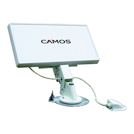
- Seite 1 Selfsat TOP Plus Dach-Flachantenne mit kompakter Dreheinheit Zusatz Montage- und Bedienungsanleitung www.camos-multimedia.com...
- Seite 2 1. Inhalt der Verpackung: Anzahl Beschreibung Antenne Selfsat-H21D mit Halterung Dreheinheit (vormontiert) Stabilisierungsplatten (1Haupt- und 1 Zusatzplatte) Grundplatte Handrad Kurbel Feder Gleitring Skalenscheibe Antennenkabel 5m einseitig mit F-Stecker F-Stecker Gel-Kappe Dachdurchführung Kompass Schrauben 2. Benötigtes Werkzeug und Material (nicht im Lieferumfang) Bohrmaschine / Bohrschrauber Bohrer 1,5mm Bohrer 13mm...
- Seite 3 3. Vorbereitung der Installation Suchen Sie eine geeignete Stelle auf dem Fahrzeugdach aus. Idealerweise sollte die Antenne in alle Richtungen frei drehbar sein, und in keiner Position durch andere Dachaufbauten abgeschattet werden. Achten Sie darauf, dass diese Stelle auch im Innenraum frei zugänglich ist und keine Lampen, Kabel oder Einbauten beim Durchbohren des Daches beschädigt werden.
- Seite 4 4. Montage der Dreheinheit Schneiden Sie mit der Lochsäge ein Loch von 38mm in das Dach. Tragen Sie auf der Unterseite der Dreheinheit jeweils um den Mittelzapfen herum und entlang der Außenkante der Dreheinheit einen ca. 0,5 cm dicken Strang Sikaflex®. Befolgen Sie dabei die Anweisungen des Herstellers mit Hinsicht auf die Vorbereitung der Oberfläche, das Auftragen und das Aushärten.
- Seite 5 Befestigen Sie nun die Antenne mit vormontierter Halterung an der Antenne mit vormontierter Halterung an der Dreheinheit mittels der 3 beigefügten Schrauben mit Muttern (M5x62mm). 5. Anschließen der Antenne Schließen Sie das Kabel mit dem F-Stecker an die Antenne an. Führen Stecker an die Antenne an.
- Seite 6 Ebenfalls auf der Scheibe finden Sie die Position der einzelnen Satelliten. Ermitteln Sie mit Hilfe des beigelegten Kompasses Norden. Drehen Sie die Skalenscheibe mit der Kennzeichnung N nach Norden. Das Handrad wird nun mit der Zeigerspitze in den Bereich des gewünschten Satelliten gedreht.
- Seite 7 Achtung: Das Fahren mit aufgerichteter oder nur teilweise umgelegter Antenne kann zu Schäden an der Getriebe- mechanik führen. Technische Daten: Modelname Camos SelfSat Top Plus Eingangsfrequenz 10.7 - 12.75 GHz Polarisation Dual Linear ( Horizontal und vertikal ) Antennenempfangsleistung 34,5 dBi bei 12.75 GHz...
- Seite 8 IMC GmbH Carl-Zeiss-Str.7 22946 Trittau Tel.: 04154-80830 Fax: 04154-808320 info@imc-multimedia.com www.camos-multimedia.com...
- Seite 9 Selfsat TOP Plus Satellite Flat Antenna with Lift and Rotation Unit Manual www.camos-multimedia.com...
- Seite 10 5. Contents: Quantity Description Antenna Selfsat-H21D Lift and Rotation Unit (pre-assembled) Ceiling Support plates Ceiling plate Rotation handle Elevation handle Spring Washer Graduation disc Antenna cable 5m one side with F-series connector F-connector Protector Gel Cable entry box Screws 6. Tools required: Electric Drill Drill bits: 1,5mm and 13mm Hole saw 38 mm diameter...
- Seite 11 7. Installation Planning Decide where you wish to mount your satellite system. Location of the lift assembly must allow antenna to point towards the rear of the vehicle when resting in the travel position, and must clear all roof mounted equipment when being raised, lowered or rotated. The inside ceiling must be clear of obstructions to ceiling plate and handle.
- Seite 12 8. Mounting Using a 38mm diameter hole saw, cut a hole through the roof and ceiling for the centre shaft. Apply a layer of approx. 0,5 cm thick of adhesive such as Sikaflex® on the bottom of the base plate. Follow the manufacturer’s guidelines for surface preparation, application and curing.
- Seite 13 5. Connecting the Antenna Connect the coaxial cable to the antenna and tighten. Feed the cable Feed the cable sidewise through the lift assembly, then insert cable through gland in through gland in rear of roof entry box and push cable into vehicle. Leave 70 cm of cable Leave 70 cm of cable (see indication) from antenna to roof entry.
- Seite 14 The graduation disc also will be used to indicate the approximate direction and position of the desired satellite. With the enclosed compass find out the direction north and turn the Indicator "N" into this direction. Turn the indicator of rotation handle into the area of desired satellite, which appears highlighted in colour on the graduation disc.
- Seite 15 Align the pointers on the ceiling plate and rotation handle before you lower the Antenna. Technical Details: Model: Camos SelfSat Top Plus Frequency range : 10.7 - 12.75 GHz Polarisation Dual Linear ( horizontal and vertical ) Gain 34,5 dBi bei 12.75 GHz...
- Seite 16 IMC GmbH (Camos Europe) Carl-Zeiss-Str. 7 22946 Trittau Tel 04154 / 8083 - 0 www.camos-multimedia.com info@camos-multimedia.com...