Herunterladen Inhalt Inhalt Diese Seite drucken
MSI MPG Z490 GAMING EDGE WIFI Kurzanleitung
Vorschau ausblenden Andere Handbücher für MPG Z490 GAMING EDGE WIFI:
Inhaltsverzeichnis

Werbung

Verfügbare Sprachen

Verfügbare Sprachen

Quick Start
Thank you for purchasing the MSI®
MPG Z490 GAMING EDGE WIFI
motherboard. This Quick Start section provides demonstration
diagrams about how to install your computer. Some of the
installations also provide video demonstrations. Please link to the
URL to watch it with the web browser on your phone or tablet. You
may have even link to the URL by scanning the QR code.
Kurzanleitung
Danke, dass Sie das MSI®
MPG Z490 GAMING EDGE WIFI
Motherboard gewählt haben. Dieser Abschnitt der Kurzanleitung
bietet eine Demo zur Installation Ihres Computers. Manche
Installationen bieten auch die Videodemonstrationen. Klicken Sie
auf die URL, um diese Videoanleitung mit Ihrem Browser auf Ihrem
Handy oder Table anzusehen. Oder scannen Sie auch den QR Code
mit Ihrem Handy, um die URL zu öffnen.
Présentation rapide
Merci d'avoir choisi la carte mère MSI®
MPG Z490 GAMING
EDGE
WIFI. Ce manuel fournit une rapide présentation avec des
illustrations explicatives qui vous aideront à assembler votre
ordinateur. Des tutoriels vidéo sont disponibles pour certaines
étapes. Cliquez sur le lien fourni pour regarder la vidéo sur votre
téléphone ou votre tablette. Vous pouvez également accéder au lien
en scannant le QR code qui lui est associé.
Быстрый старт
Благодарим вас за покупку материнской платы MSI®
MPG Z490
GAMING EDGE
WIFI. В этом разделе представлена информация,
которая поможет вам при сборке комьютера. Для некоторых
этапов сборки имеются видеоинструкции. Для просмотра видео,
необходимо открыть соответствующую ссылку в веб-браузере
на вашем телефоне или планшете. Вы также можете выполнить
переход по ссылке, путем сканирования QR-кода.
I
Quick Start

Werbung

Inhaltsverzeichnis
loading

Inhaltszusammenfassung für MSI MPG Z490 GAMING EDGE WIFI

  • Seite 1 Handy oder Table anzusehen. Oder scannen Sie auch den QR Code mit Ihrem Handy, um die URL zu öffnen. Présentation rapide Merci d’avoir choisi la carte mère MSI® MPG Z490 GAMING EDGE WIFI. Ce manuel fournit une rapide présentation avec des illustrations explicatives qui vous aideront à...
  • Seite 2 Installing a Processor/ Installation des Prozessors/ Installer un processeur/ Установка процессора ⚽ https://youtu.be/4ce91YC3Oww Quick Start...
  • Seite 3 Installing DDR4 memory/ Installation des DDR4-Speichers/ Installer une mémoire DDR4/ Установка памяти DDR4 ⚽ http://youtu.be/T03aDrJPyQs DIMMA1 DIMMA2 DIMMA2 DIMMA2 DIMMB1 DIMMB2 DIMMB2 Quick Start...
  • Seite 4 Connecting the Front Panel Header/ Anschließen der Frontpanel-Stiftleiste/ Connecter un connecteur du panneau avant/ Подключение разъемов передней панели ⚽ http://youtu.be/DPELIdVNZUI Power LED Power Switch JFP1 Reserved HDD LED Reset Switch HDD LED + Power LED + HDD LED - Power LED - Reset Switch Power Switch JFP1...
  • Seite 5 Installing the Motherboard/ Installation des Motherboards/ Installer la carte mère/ Установка материнской платы ⚽ https://youtu.be/wWI6Qt51Wnc Torque: 3 kgf·cm* *3 kgf·cm = 0.3 N·m = 2.6 lbf·in Quick Start...
  • Seite 6 Connecting the Power Connectors/ Stromanschlüsse anschliessen/ Connecter les câbles du module d’alimentation/ Подключение разъемов питания ⚽ http://youtu.be/gkDYyR_83I4 ATX_PWR1 CPU_PWR2 CPU_PWR1 Quick Start...
  • Seite 7 Installing SATA Drives/ Installation der SATA-Laufwerke/ Installer le disque dur SATA/ Установка дисков SATA ⚽ http://youtu.be/RZsMpqxythc Quick Start...
  • Seite 8 Installing a Graphics Card/ Einbau der Grafikkarte/ Installer une carte graphique/ Установка дискретной видеокарты ⚽ http://youtu.be/mG0GZpr9w_A VIII Quick Start...
  • Seite 9 Connecting Peripheral Devices/ Peripheriegeräte/ Connecter un périphérique anschliessen/ Подключение периферийных устройств Quick Start...
  • Seite 10: Power On/ Einschalten/ Mettre Sous-Tension/ Включение Питания

    Power On/ Einschalten/ Mettre sous-tension/ Включение питания Quick Start...
  • Seite 11: Inhaltsverzeichnis

    Contents Safety Information ....................3 Specifications ......................4 Package contents ....................9 Rear I/O Panel ..................... 10 LAN Port LED Status Table .................. 10 Audio Ports Configuration ..................10 Realtek Audio Console ..................11 Overview of Components ..................14 CPU Socket ......................15 DIMM Slots ......................
  • Seite 12 Resetting BIOS ...................... 35 Updating BIOS ....................... 35 EZ Mode ........................ 37 Advanced Mode ....................41 OC Menu........................ 42 Contents...
  • Seite 13: Safety Information

    Safety Information ∙ The components included in this package are prone to damage from electrostatic discharge (ESD). Please adhere to the following instructions to ensure successful computer assembly. ∙ Ensure that all components are securely connected. Loose connections may cause the computer to not recognize a component or fail to start.
  • Seite 14: Specifications

    ** SATA5 & SATA6 will be unavailable when installing M.2 SATA/PCIe SSD in the M2_2 slot. *** Before using Intel® Optane™ memory modules, please ensure that you have updated the drivers and BIOS to the latest version from MSI website. Continued on next page Specifications...
  • Seite 15 Continued from previous page Intel® Z490 Chipset ∙ Supports RAID 0, RAID1, RAID 5 and RAID 10 for SATA RAID storage devices ∙ Supports RAID 0 and RAID 1 for M.2 PCIe storage devices 1x Realtek® RTL8125B-CG 2.5G LAN Controller ∙...
  • Seite 16: Hardware Monitor

    Continued from previous page ∙ 1x 24-pin ATX main power connector ∙ 1x 8-pin ATX 12V power connector ∙ 1x 4-pin ATX 12V power connector ∙ 6x SATA 6Gb/s connectors ∙ 1x USB 3.2 Gen 1 5Gbps Type-C port ∙ 1x USB 3.2 Gen 1 5Gbps connector (support additional 2 USB 3.2 Gen 1 5Gbps ports) ∙...
  • Seite 17 Continued from previous page ∙ Drivers ∙ DRAGON CENTER ∙ Intel Extreme Tuning Utility ∙ MSI App Player (BlueStacks) Software ∙ Open Broadcaster Software (OBS) ∙ CPU-Z MSI GAMING ∙ Google Chrome™, Google Toolbar, Google Drive ∙ Norton™ Internet Security Solution ∙...
  • Seite 18 Continued from previous page ∙ LED ▪ Mystic Light ▪ Mystic Light Extension (RGB) ▪ Mystic Light Extension (RAINBOW) ▪ Mystic Light Sync ▪ EZ DEBUG LED ▪ EZ LED Control ∙ Protection ▪ PCIe Steel Armor ▪ Pre-installed IO shielding ∙...
  • Seite 19: Package Contents

    Package contents Please check the contents of your motherboard package. It should contain: Motherboard MPG Z490 GAMING EDGE WIFI User manual Documentation Case stand-off notification Quick installation guide Application Driver DVD Cables SATA 6G cables (2 cables/pack) Wi-Fi Antenna Case badge...
  • Seite 20: Rear I/O Panel

    Rear I/O Panel Audio Ports USB 3.2 Gen 2 10Gbps 2.5Gbps LAN Type-A PS/2 Displayport Optical S/PDIF-Out USB 3.2 Gen 1 5Gbps USB 2.0 HDMI port USB 3.2 Gen 2x2 20Gbps WiFi antenna Type-C connector LAN Port LED Status Table Link/ Activity LED Speed LED Status...
  • Seite 21: Realtek Audio Console

    Realtek Audio Console After Realtek Audio Console is installed. You can use it to change sound settings to get better sound experience. Application Enhancement Device Selection Main Volume Connector Settings Jack Status ∙ Device Selection - allows you to select a audio output source to change the related options.
  • Seite 22 Audio jacks to headphone and microphone diagram Audio jacks to stereo speakers diagram AUDIO INPUT Audio jacks to 7.1-channel speakers diagram AUDIO INPUT Rear Front Side Center/ Subwoofer Rear I/O Panel...
  • Seite 23: Installing Antennas

    Installing antennas 1. Screw the antennas tight to the antenna connectors as shown below. 2. Orient the antennas. Rear I/O Panel...
  • Seite 24: Overview Of Components

    Overview of Components DIMMB1 DIMMA2 DIMMB2 CPU Socket CPU_PWR1 DIMMA1 JRGB2 CPU_PWR2 CPU_FAN1 JRAINBOW2 PUMP_FAN1 SYS_FAN6 ATX_PWR1 JUSB4 SYS_FAN1 M2_1 PCI_E1 JUSB3 SATA▼1▲2 PCI_E2 JCI1 SATA▼3▲4 PCI_E3 SYS_FAN5 M2_2 SYS_FAN4 LED_SW1 PCI_E4 JRTD3 JFP1 JTBT1 JAUD1 SATA6 JRGB1 SATA5 SYS_FAN2 JTPM1 JUSB1 SYS_FAN3...
  • Seite 25: Cpu Socket

    ∙ the CPU. ∙ Please retain the CPU protective cap after installing the processor. MSI will deal with Return Merchandise Authorization (RMA) requests if only the motherboard comes with the protective cap on the CPU socket. When installing a CPU, always remember to install a CPU heatsink. A CPU heatsink ∙...
  • Seite 26: Dimm Slots

    It is recommended to use a more efficient memory cooling system for full DIMMs ∙ installation or overclocking. The stability and compatibility of installed memory module depend on installed CPU ∙ and devices when overclocking. ∙ Please refer www.msi.com for more information on compatible memory. Overview of Components...
  • Seite 27: Pci_E1~4: Pcie Expansion Slots

    ⚠ Important ∙ If you install a large and heavy graphics card, you need to use a tool such as MSI Gaming Series Graphics Card Bolster to support its weight to prevent deformation of the slot. For a single PCIe x16 expansion card installation with optimum performance, using ∙...
  • Seite 28: Cpu_Pwr1, Atx_Pwr1: Power Connectors

    CPU_PWR1, ATX_PWR1: Power Connectors These connectors allow you to connect an ATX power supply. CPU_PWR1 Ground +12V Ground +12V Ground +12V Ground +12V CPU_PWR2 Ground +12V Ground +12V +3.3V +3.3V +3.3V -12V Ground Ground PS-ON# Ground Ground Ground ATX_PWR1 Ground Ground PWR OK 5VSB...
  • Seite 29: Jfp1, Jfp2: Front Panel Connectors

    JFP1, JFP2: Front Panel Connectors These connectors connect to the switches and LEDs on the front panel. Power LED Power Switch JFP1 Reserved HDD LED Reset Switch HDD LED + Power LED + HDD LED - Power LED - Reset Switch Power Switch Reset Switch Power Switch...
  • Seite 30: M2_1~2: M.2 Slots (Key M)

    M2_1~2: M.2 Slots (Key M) ⚽ Video Demonstration Watch the video to learn how to Install M.2 module. http://youtu.be/JCTFABytrYA ⚠ Important ∙ Intel® RST only supports PCIe M.2 SSD with UEFI ROM. ∙ Intel® Optane™ Memory Ready for all M.2 slots. Installing M.2 module 1.
  • Seite 31 3. Move the position of the standoffs according to your M.2 SSDs length if need. 4. Insert your M.2 SSD into the M.2 slot at a 30-degree angle. 5. Secure the M.2 SSD in place with the supplied M.2 8.5H screw. 8.5H screw 30º...
  • Seite 32: Sata1~6: Sata 6Gb/S Connectors

    SATA1~6: SATA 6Gb/s Connectors These connectors are SATA 6Gb/s interface ports. Each connector can connect to one SATA device. SATA2 SATA1 SATA4 SATA3 SATA5 ⚠ SATA6 Important Please do not fold the SATA cable at a 90-degree angle. Data loss may result during ∙...
  • Seite 33: Cpu_Fan1, Pump_Fan1, Sys_Fan1~6: Fan Connectors

    CPU_FAN1, PUMP_FAN1, SYS_FAN1~6: Fan Connectors Fan connectors can be classified as PWM (Pulse Width Modulation) Mode or DC Mode. PWM Mode fan connectors provide constant 12V output and adjust fan speed with speed control signal. DC Mode fan connectors control fan speed by changing voltage. You can follow the instruction below to adjust the fan connector to PWM or DC Mode.
  • Seite 34: Jusb1~2: Usb 2.0 Connectors

    ∙ In order to recharge your iPad,iPhone and iPod through USB ports, please install MSI DRAGON CENTER utility. JUSB4: USB 3.2 Gen 1 Type-C Connector This connector allows you to connect USB 3.2 Gen 1 Type-C connector on the front panel.
  • Seite 35: Jusb3: Usb 3.2 Gen 1 Connector

    JUSB3: USB 3.2 Gen 1 Connector These connectors allow you to connect USB 3.2 Gen 1 ports on the front panel. Power USB2.0+ USB3_RX_DN USB2.0- USB3_RX_DP Ground Ground USB3_TX_C_DP USB3_TX_C_DN USB3_TX_C_DN USB3_TX_C_DP Ground Ground USB3_RX_DP USB2.0- USB3_RX_DN USB2.0+ Power No Pin ⚠...
  • Seite 36: Jtbt1: Thunderbolt Add-On Card Connector

    JTBT1: Thunderbolt Add-on Card Connector This connector allows you to connect the add-on Thunderbolt I/O card. FORCE_PWR SCI_EVENT SLP_S3# SLP_S5# JRTD3: Intel RTD3 Connector This connector allows you to connect the RTD3 connector on the add-on Thunderbolt I/O card that supports RTD3. WAKE PWR EN Overview of Components...
  • Seite 37: Jbat1: Clear Cmos (Reset Bios) Jumper

    JBAT1: Clear CMOS (Reset BIOS) Jumper There is CMOS memory onboard that is external powered from a battery located on the motherboard to save system configuration data. If you want to clear the system configuration, set the jumper to clear the CMOS memory. Keep Data Clear CMOS/ (default)
  • Seite 38: Jci1: Chassis Intrusion Connector

    JCI1: Chassis Intrusion Connector This connector allows you to connect the chassis intrusion switch cable. Normal Trigger the chassis intrusion event (default) Using chassis intrusion detector 1. Connect the JCI1 connector to the chassis intrusion switch/ sensor on the chassis. 2.
  • Seite 39: Jrgb1~2: Rgb Led Connectors

    (12V/G/R/B) with the maximum power rating of 3A (12V). ∙ Always turn off the power supply and unplug the power cord from the power outlet before installing or removing the RGB LED strip. Please use MSI’s software to control the extended LED strip. ∙ Overview of Components...
  • Seite 40: Jrainbow1~2: Addressable Rgb Led Connectors

    (5V). In the case of 20% brightness, the connector supports up to 200 LEDs. ∙ Always turn off the power supply and unplug the power cord from the power outlet before installing or removing the RGB LED strip. Please use MSI’s software to control the extended LED strip. ∙ Overview of Components...
  • Seite 41: Onboard Leds

    Onboard LEDs EZ Debug LED These LEDs indicate the debug status of the motherboard. CPU - indicates CPU is not detected or fail. DRAM - indicates DRAM is not detected or fail. VGA - indicates GPU is not detected or fail. BOOT - indicates the booting device is not detected or fail.
  • Seite 42: Installing Os, Drivers & Utilities

    Installing OS, Drivers & Utilities Please download and update the latest utilities and drivers at www.msi.com Installing Windows® 10 1. Power on the computer. 2. Insert the Windows® 10 installation disc/USB into your computer. 3. Press the Restart button on the computer case.
  • Seite 43: Uefi Bios

    UEFI BIOS MSI UEFI BIOS is compatible with UEFI (Unified Extensible Firmware Interface) architecture. The UEFI BIOS firmware infrastructure has many new functions and advantages that traditional BIOS cannot achieve. It will fully support future PCs and devices that comply with UEFI firmware architecture.
  • Seite 44: Bios Setup

    BIOS Setup The default settings offer the optimal performance for system stability in normal conditions. You should always keep the default settings to avoid possible system damage or failure booting unless you are familiar with BIOS. ⚠ Important BIOS items are continuously update for better system performance. Therefore, the ∙...
  • Seite 45: Resetting Bios

    Updating BIOS Updating BIOS with M-FLASH Before updating: Please download the latest BIOS file that matches your motherboard model from MSI website. And then save the BIOS file into the USB flash drive. Updating BIOS: 1. Insert the USB flash drive that contains the update file into the USB port.
  • Seite 46 Make sure the LAN driver is already installed and the internet connection is set properly. Updating BIOS: 1. Install and launch MSI DRAGON CENTER and go to Support page. 2. Select Live Update and click on Advance button. 3. Click on Scan button to search the latest BIOS file.
  • Seite 47: Ez Mode

    EZ Mode At EZ mode, it provides the basic system information and allows you to configure the basic setting. To configure the advanced BIOS settings, please enter the Advanced Mode by pressing the Setup Mode switch or F7 function key. Screenshot XMP Profile Setup Mode switch...
  • Seite 48 ∙ Language - allows you to select language of BIOS setup. ∙ System information - shows the CPU/ DDR speed, CPU/ MB temperature, MB/ CPU type, memory size, CPU/ DDR voltage, BIOS version and build date. ∙ Boot device priority bar - you can move the device icons to change the boot priority. The boot priority from high to low is left to right.
  • Seite 49 ∙ Favorites - click on this button or press the F3 key to show the Favorites window. It provides 5 menus for you to create personal BIOS menu where you can save and access favorite/ frequently-used BIOS setting items. ▪ To add a BIOS item to a favorite menu 1.
  • Seite 50 ▪ To delete a BIOS item from favorite menu 1. Select a BIOS item on favorite menu. 2. Right-click or press F2 key. 3. Choose Delete and click on OK. UEFI BIOS...
  • Seite 51: Advanced Mode

    Advanced Mode Press Setup Mode switch or F7 function key can switch between EZ Mode and Advanced Mode in BIOS setup. BIOS menu BIOS menu selection selection Menu display ∙ BIOS menu selection - the following options are available: ▪ SETTINGS - allows you to specify the parameters for chipset and boot devices. ▪...
  • Seite 52: Oc Menu

    OC Menu This menu allows you to configure the frequencies and voltages for overclocking. Please note that, higher frequency and voltage may benefit overclocking capability but cause system un-stability. ⚠ Important Overclocking your PC manually is only recommended for advanced users. ∙...
  • Seite 53 ▶ Core X X of X xxxx MHz [Auto] Allows you to set the CPU ratios for different number of active cores. These items only appear when CPU Ratio Apply Mode set to Per Core. ▶ Turbo Ratio Offset Value [Auto] Sets the CPU Turbo ratio offset value.
  • Seite 54 ▶ Extreme Memory Profile (XMP) [Disabled] XMP (Extreme Memory Profile) is the overclocking technology by memory module. Please enable XMP or select a profile of memory module for overclocking the memory. This item will be available when the memory modules that support XMP is installed.
  • Seite 55 ▶ CPU Core Voltage Mode [Auto]* Sets the CPU Core voltage mode. ▶ CPU Voltages control [Auto] These options allow you to set the voltages related to CPU. If set to Auto, BIOS will set these voltages automatically or you can set it manually. ▶...
  • Seite 56 UEFI BIOS...
  • Seite 57 Inhalt Sicherheitshinweis ....................3 Spezifikationen ...................... 4 Packungsinhalt ....................10 Rückseite E/A ...................... 11 LAN Port LED Zustandstabelle ................11 Konfiguration der Audioanschlüsse ..............11 Realtek Audio Console ..................12 Übersicht der Komponenten ................15 CPU Sockel ......................16 DIMM Steckplätze ................... 17 PCI_E1~4: PCIe Erweiterungssteckplätze ............
  • Seite 58 Reset des BIOS ..................... 36 Aktualisierung des BIOS ..................36 EZ Modus ......................38 Erweiterter Modus ....................41 OC Menü........................ 42 Inhalt...
  • Seite 59: Sicherheitshinweis

    Sicherheitshinweis ∙ Die im Paket enthaltene Komponenten sind der Beschädigung durch elektrostatischen Entladung (ESD). Beachten Sie bitte die folgenden Hinweise, um die erfolgreichen Computermontage sicherzustellen. ∙ Stellen Sie sicher, dass alle Komponenten fest angeschlossen sind. Lockere Steckverbindungen können Probleme verursachen, zum Beispiel: Der Computer erkennt eine Komponente nicht oder startet nicht.
  • Seite 60: Spezifikationen

    ∙ Unterstützt non-ECC, ungepufferte Speicher ∙ Unterstützt Intel® Extreme Memory Profile (XMP) * Weitere Informationen zu kompatiblen Speicher finden Sie unter: http://www.msi.com ∙ 1x PCIe 3.0 x16 Steckplatz (vom CPU) ∙ 1x PCIe 3.0 x16 Steckplatz (x4 Modus, von PCH) Erweiterung- anschlüsse...
  • Seite 61: Aufbewahrung

    *** Bevor Sie Intel® Optane Speichermodule verwenden, stellen Sie bitte über ™ Downloads von der MSI Website sicher, dass die Treiber und das BIOS auf dem neuesten Stand sind. Intel® Z490 Chipsatz ∙ Unterstützt RAID 0, RAID1, RAID 5 und RAID 10 für SATA RAID Speichergeräte...
  • Seite 62 Fortsetzung der vorherigen Seite Intel® AX201 ∙ MU-MIMO TX/RX, 2,4GHz/ 5GHz (160MHz) mit Datenraten bis zu 2.4Gbit/s Wireless/ Bluetooth ∙ 802.11ac; WiFi 6 ist vorzertifiziert ∙ Bluetooth 5.1, FIPS, FISMA ∙ 1x M.2_3 Sockel mit E Key (Wi-Fi Modus) ∙ 1x PS/2 Tastatur/ Maus-Combo-Anschluss ∙...
  • Seite 63 ∙ ACPI 6.2, SM BIOS 3.2 ∙ Mehrsprachenunterstützung ∙ Treiber ∙ DRAGON CENTER ∙ Intel Extreme Tuning Utility ∙ MSI App Player (BlueStacks) Software ∙ Open Broadcaster Software (OBS) ∙ CPU-Z MSI GAMING ∙ Google Chrome , Google Toolbar, Google Drive ™...
  • Seite 64: Besondere Funktionen

    ∙ Ambient Link ∙ Benutzer-Scenario Dragon Center ∙ Monitor(Hardware Funktionen Monitor) ∙ True Color Weitere Informationen finden Sie unter http://download.msi.com/ ∙ Live Update manual/mb/DRAGONCENTER2.pdf ∙ DPC Latency Tuner ∙ Speed Up ∙ Smart Tool ∙ Super Charger ∙ Audio ▪ Audio Boost ∙...
  • Seite 65 Fortsetzung der vorherigen Seite ∙ LED ▪ Mystic Light ▪ Mystic Light Extension (RGB) ▪ Mystic Light Extension (RAINBOW) ▪ Mystic Light Sync ▪ EZ DEBUG LED ▪ EZ LED Steuerung ∙ Schutz ▪ PCIe Steel Armor ▪ Vorinstallierte Anschlussblende ∙...
  • Seite 66: Packungsinhalt

    Packungsinhalt Überprüfen Sie den Packungsinhalt des Mainboards. Die Packung sollte enthalten: Motherboard MPG Z490 GAMING EDGE WIFI Benutzerhandbuch Dokumentation Notifizierung für Gehäuse-abstandshalter Schnellinstallationsanleitung Anwendung Treiber-DVD Kabel SATA 6G Kabel (2 Kabel pro Packung) Wi-Fi Antenne Gehäuse-Aufkleber Zubehör SATA-Kabelaufkleber Produktregistrierungskarte M.2 Schraube (3 Stück pro Packung) ⚠...
  • Seite 67: Rückseite E/A

    Rückseite E/A Audioanschlüsse USB 3.2 Gen 2 10Gbit/s 2,5Gbit/s LAN Typ-A PS/2 Displayport Optischer S/PDIF- USB 3.2 Gen 1 5Gbit/s USB 2.0 HDMI Ausgang Anschluss USB 3.2 Gen 2x2 20Gbit/s WiFi Antennen- Typ-C anschlüsse LAN Port LED Zustandstabelle Verbindung/ Aktivität LED Geschwindigkeit LED Zustand Bezeichnung...
  • Seite 68: Realtek Audio Console

    Realtek Audio Console Nach der Installation des Realtek Audio Console-Treibers, können Sie die Audioeinstellungen verändern, um ein optimales Klangerlebnis erzeugen. Optimierungen Geräteauswahl Lautstärke Anschluss Verbindungsstatus ∙ Geräteauswahl - Ermöglicht die Auswahl der Audio-Ausgangs Quelle. Das aktuell aktivierte Gerät ist mit einem Haken gekennzeichnet. ∙...
  • Seite 69: Audiobuchsen Für Stereo-Lautsprecher

    Audiobuchsen für den Anschluss von einem Kopfhörer und Mikrofon Audiobuchsen für Stereo-Lautsprecher AUDIO INPUT Audiobuchsen für 7.1 Kanal Anlage AUDIO INPUT Rear Front Side Center/ Subwoofer Rückseite E/A...
  • Seite 70: Antennen Installieren

    Antennen installieren 1. Schrauben Sie die Antennen fest an die Antennenanschlüsse, wie gezeigt. 2. Richten Sie die Antennenspitzen aus. Rückseite E/A...
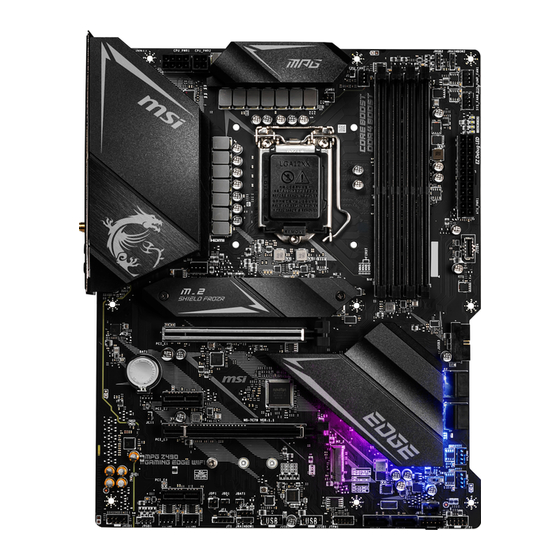
  • Seite 71: Übersicht Der Komponenten

    Übersicht der Komponenten DIMMB1 DIMMA2 DIMMB2 CPU Sockel CPU_PWR1 DIMMA1 JRGB2 CPU_PWR2 CPU_FAN1 JRAINBOW2 PUMP_FAN1 SYS_FAN6 ATX_PWR1 JUSB4 SYS_FAN1 M2_1 PCI_E1 JUSB3 SATA▼1▲2 PCI_E2 JCI1 SATA▼3▲4 PCI_E3 SYS_FAN5 M2_2 SYS_FAN4 LED_SW1 PCI_E4 JRTD3 JFP1 JTBT1 JAUD1 SATA6 JRGB1 SATA5 SYS_FAN2 JTPM1 JUSB1 SYS_FAN3...
  • Seite 72: Cpu Sockel

    Sie jedoch bitte sicher, dass die betroffenen Komponenten mit den abweichenden Einstellungen während des Übertaktens zurecht kommen. Von jedem Versuch des Betriebes außerhalb der Produktspezifikationen kann nur abgeraten werden. MSI übernehmt keinerlei Garantie für die Schäden und Risiken, die aus einem unzulässigem Betrieb oder einem Betrieb außerhalb der Produktspezifikation resultieren.
  • Seite 73: Dimm Steckplätze

    DIMMs oder beim Übertakten zu verwenden. Die Stabilität und Kompatibilität beim Übertakten der installierten Speichermodule ∙ sind abhängig von der installierten CPU und den installierten Geräten. Weitere Informationen zu kompatiblen Speichermodulen finden Sie unter: ∙ http://www.msi.com Übersicht der Komponenten...
  • Seite 74: Pci_E1~4: Pcie Erweiterungssteckplätze

    PCI_E1~4: PCIe Erweiterungssteckplätze PCI_E1: PCIe 3.0 x16 (CPU) PCI_E2: PCIe 3.0 x1 (PCH) PCI_E3: PCIe 3.0 x4 (PCH) PCI_E4: PCIe 3.0 x1 (PCH) ⚠ Wichtig ∙ Wenn Sie eine große und schwere Grafikkarte einbauen, benötigen Sie einen Grafikkarten-Stabilisator (Graphics Card Bolster) der das Gewicht trägt und eine Verformung des Steckplatzes vermeidet.
  • Seite 75: Cpu_Pwr1, Atx_Pwr1: Stromanschlüsse

    CPU_PWR1, ATX_PWR1: Stromanschlüsse Mit diesen Anschlüssen verbinden Sie die ATX Stromstecker. CPU_PWR1 Ground +12V Ground +12V Ground +12V Ground +12V CPU_PWR2 Ground +12V Ground +12V +3.3V +3.3V +3.3V -12V Ground Ground PS-ON# Ground Ground Ground ATX_PWR1 Ground Ground PWR OK 5VSB +12V +12V...
  • Seite 76: Jfp1, Jfp2: Frontpanel-Anschlüsse

    JFP1, JFP2: Frontpanel-Anschlüsse Diese Anschlüsse verbinden die Schalter und LEDs des Frontpanels. Power LED Power Switch JFP1 Reserved HDD LED Reset Switch HDD LED + Power LED + HDD LED - Power LED - Reset Switch Power Switch Reset Switch Power Switch Reserved No Pin...
  • Seite 77: M2_1~2: M.2 Steckplätze (Key M)

    M2_1~2: M.2 Steckplätze (Key M) ⚽ Video-Demonstration Eine anschauliche Darstellung zur Installation eines M.2 Moduls finden Sie im Video. http://youtu.be/JCTFABytrYA ⚠ Wichtig ∙ Intel® RST unterstützt nur PCIe M.2 SSD mit UEFI ROM. ∙ Intel® Optane Technik unterstützt alle M.2 Steckplätze. ™...
  • Seite 78 3. Wählen Sie die Montageposition entsprechend Ihrer M.2 SSD Länge. 4. Stecken Sie eine M.2-SSD im 30-Grad-Winkel in den M.2-Steckplatz. 5. Schrauben Sie den M.2 SSD mit 8,5H M.2-Schraube. 8,5H Schraube 30º 30º Abstandshalter 6. Setzen Sie den M.2 SHIELD FROZR-Kühlkörper wieder ein und sichern Sie ihn. Übersicht der Komponenten...
  • Seite 79: Sata1~6: Sata 6Gb/S Anschlüsse

    SATA1~6: SATA 6Gb/s Anschlüsse Dieser Anschluss basiert auf der Hochgeschwindigkeitsschnittstelle SATA 6 Gb/s. Pro Anschluss kann ein SATA Gerät angeschlossen werden. SATA2 SATA1 SATA4 SATA3 SATA5 ⚠ SATA6 Wichtig Knicken Sie das SATA-Kabel nicht in einem 90° Winkel. Datenverlust könnte die ∙...
  • Seite 80: Cpu_Fan1, Pump_Fan1, Sys_Fan1~6: Stromanschlüsse Für Lüfter

    CPU_FAN1, PUMP_FAN1, SYS_FAN1~6: Stromanschlüsse für Lüfter Diese Anschlüsse können im PWM (Pulse Width Modulation) Modus oder Spannungsmodus betrieben werden. Im PWM-Modus bieten die Lüfteranschlüsse konstante 12V Ausgang und regeln die Lüftergeschwindigkeit per Drehzahlsteuersignal. Im DC-Modus bestimmen die Lüfteranschlüsse die Lüftergeschwindigkeit durch Ändern der Spannung. Folgen Sie den folgenden Anweisungen, um den PWM- oder DC-Modus auszuwählen.
  • Seite 81: Jusb1~2: Usb 2.0 Anschlüsse

    Um ein iPad, iPhone und einen iPod über USB-Anschlüsse aufzuladen, installieren ∙ Sie bitte die MSI® DRAGON CENTER Software. JUSB4: USB 3.2 Gen 1 Typ-C Anschluss Mit diesem Anschluss können Sie den USB 3.2 Gen 1 Typ-C Anschluss auf dem Frontpanel verbinden.
  • Seite 82: Jusb3: Usb 3.2 Gen 1 Anschluss

    JUSB3: USB 3.2 Gen 1 Anschluss Mit diesem Anschluss können Sie die USB 3.2 Gen 1 Anschlüsse auf dem Frontpanel verbinden. Power USB2.0+ USB3_RX_DN USB2.0- USB3_RX_DP Ground Ground USB3_TX_C_DP USB3_TX_C_DN USB3_TX_C_DN USB3_TX_C_DP Ground Ground USB3_RX_DP USB2.0- USB3_RX_DN USB2.0+ Power No Pin ⚠...
  • Seite 83: Jtbt1: Anschluss Für Thunderbolt-Erweiterungskarte

    JTBT1: Anschluss für Thunderbolt-Erweiterungskarte Mit diesem Anschluss können Sie eine Ein-/Ausgang der Thunderbolt- Erweiterungskarte anschließen. FORCE_PWR SCI_EVENT SLP_S3# SLP_S5# JRTD3: Intel RTD3 Anschluss Mit diesem Anschluss können Sie den RTD3-Anschluss an die Thunderbolt-E / A-Zusatzkarte anschließen mit RTD3-Unterstützung anschließen. WAKE PWR EN Übersicht der Komponenten...
  • Seite 84: Jbat1: Clear Cmos Steckbrücke (Reset Bios)

    JBAT1: Clear CMOS Steckbrücke (Reset BIOS) Der Onboard CMOS Speicher (RAM) wird durch eine externe Spannungsversorgung durch eine Batterie auf dem Motherboard versorgt, um die Daten der Systemkonfiguration zu speichern. Wenn Sie die Systemkonfiguration löschen wollen, müssen Sie die Steckbrücke für kurze Zeit umsetzen. Daten CMOS-Daten beibehalten...
  • Seite 85: Jci1: Gehäusekontaktanschluss

    JCI1: Gehäusekontaktanschluss Dieser Anschluss wird mit einem Kontaktschalter verbunden. Normal Löse den (Standardwert) Gehäuseeingriff aus Gehäusekontakt-Detektor verwenden 1. Schließen Sie den JCI1-Anschluss am Gehäusekontakt-Schalter/ Sensor am Gehäuse an. 2. Schließen Sie die Gehäuseabdeckung. 3. Gehen Sie zu BIOS > SETTINGS > Security > Chassis Intrusion Configuration. 4.
  • Seite 86: Jrgb1~2: Rgb Led Anschlüsse

    R/B) mit der maximalen Leistung von 3 A (12 V). Schalten Sie die Stromversorgung aus und ziehen Sie das Netzkabel ab, bevor Sie ∙ die RGB-LED-Streifen ein- und ausbauen. ∙ Bitte verwenden Sie die MSI-Software zur Steuerung des LED-Leuchtstreifens. Übersicht der Komponenten...
  • Seite 87: Jrainbow1~2: Adressierbare Rgb Led Anschlüsse

    3 A (5 V). Bei einer Helligkeit von 20 Prozent unterstützt dieser Anschluss bis zu 200 LEDs. Schalten Sie die Stromversorgung aus und ziehen Sie das Netzkabel ab, bevor Sie ∙ die RGB-LED-Streifen ein- und ausbauen. Bitte verwenden Sie die MSI-Software zur Steuerung des LED-Leuchtstreifens. ∙ Übersicht der Komponenten...
  • Seite 88: Onboard-Leds

    Onboard-LEDs EZ Debug LED Diese LEDs zeigen den Debug-Status des Motherboards an. CPU - CPU wird nicht erkannt oder ist fehlerhaft. DRAM - DRAM wird nicht erkannt oder ist fehlerhaft. VGA - GPU wird nicht erkannt oder ist fehlerhaft. BOOT - Boot-Gerät wird nicht erkannt oder ist fehlerhaft.
  • Seite 89: Installation Von Os, Treibern Und Utilities

    Sie DVDSetup.exe starten aus, um den Installer zu öffnen. Wenn Sie die AutoPlay-Funktionen in der Windows-Systemsteuerung ausschalten, können Sie das Programm DVD Setup.exe im Hauptverzeichnis der MSI Treiber CD auch manuell ausführen. 4. Der Installer wird findet eine Liste aller benötigten Treiber auf der Treiber/ Software-Registerkarte.
  • Seite 90: Uefi Bios

    UEFI BIOS Das MSI UEFI-BIOS ist mit der UEFI-Architektur (Unified Extensible Firmware Interface) kompatibel. Die UEFI-BIOS-Firmware-Infrastruktur hat viele neue Funktionen und Vorteile. PCs und Geräte, die auf der UEFI-Firmware-Architektur basieren, werden zukünftig vollständig unterstützt. ⚠ Wichtig Der Begriff „BIOS“ bezieht sich in diesem Benutzerhandbuch auf das UEFI-BIOS, sofern nicht anders angegeben.
  • Seite 91: Bios Setup

    BIOS Setup Die Standardeinstellungen bieten die optimale Leistung für die Systemstabilität unter Normalbedingungen. Sie sollten immer die Standardeinstellungen behalten, um mögliche Schäden des Systems oder Boot-Fehler zu vermeiden, außer Sie besitzen ausreichende BIOS Kenntnisse. ⚠ Wichtig BIOS Funktionen werden für eine bessere Systemleistung kontinuierlich ∙...
  • Seite 92: Reset Des Bios

    Aktualisierung des BIOS mit dem M-FLASH-Programm Vorbereitung: Laden Sie bitte die neueste BIOS Version, die dem Motherboard-Modell entspricht, von der offiziellen MSI Website herunter und speichern Sie die BIOS-Datei auf USB- Flash-Laufwerk. BIOS-Aktualisierungsschritte: 1. Schließen das USB-Flashlaufwerk mit der BIOS-Datei an den Computer.
  • Seite 93 Stellen Sie sicher, dass zuvor die LAN-Treiber installiert wurden und eine Internetverbindung eingerichtet ist. Schritte zur Aktualisierung des BIOS: 1. Installieren und starten Sie „MSI DRAGON CENTER“ und gehen Sie zur Support- Seite. 2. Wählen Sie Live Update aus und klicken Sie auf die Schaltfläche Advance.
  • Seite 94: Ez Modus

    EZ Modus Im EZ-Modus können Sie die Grundinformationen des Systems einsehen und grundlegende Einstellungen konfigurieren. Um sich die erweiterten BIOS- Einstellungen anzeigen zu lassen, aktivieren Sie bitte den Erweiterten Modus durch Drücken des Setup Modus Schalter oder der Funktionstaste F7. Screenshot XMP Profil Setup Modus Schalter...
  • Seite 95 ∙ Sprache - Hier können Sie die Sprache der BIOS-Einstellungen auswählen. ∙ Systeminformationen - Diese zeigt CPU/ DDR-Frequenz, CPU/ MB-Temperatur, MB/ CPU-Typ, Speicherkapazität, CPU/ DDR-Spannung, BIOS-Version und Erstellungs-Datum. ∙ Boot-Geräte Prioritätsleiste - Sie können die Gerätesymbole verschieben, um die Startreihenfolge zu ändern. Die Bootreihenfolge sind mit “hoch”(links) bis “niedrig” (rechts) bezeichnet.
  • Seite 96 ▪ Um ein BIOS-Punkte zu einer Favoritenmenü hinzufügen 1. Sie können nicht nur über einen Eintrag im BIOS-Menü sondern auch auf der Suchseite auswählen. 2. Klicken Sie mit der rechten Maustaste oder drücken Sie die Taste F2. 3. Wählen Sie die gewünschte Seite aus und klicken Sie auf OK. ▪...
  • Seite 97: Erweiterter Modus

    Erweiterter Modus Drücken Sie den Setup Modus Schalter oder die Funkionstaste F7, um zwischen dem EZ-Modus und Erweiterten-Modus im BIOS-Setup zu wechseln. BIOS-Menü BIOS-Menü -Auswahl -Auswahl Menüanzeige ∙ BIOS-Menü-Auswahl - Die folgenden Optionen stehen zur Verfügung. ▪ SETTINGS - Mit diesem Menü können Sie die Parameter für Chipsatz, Boot- Geräte angeben.
  • Seite 98: Oc Menü

    OC Menü In diesem Menü können Sie die Frequenzen und Spannungen für das Übertakten konfigurieren. Bitte beachten Sie, dass höhere Frequenzen und Spannungen die Übertaktungsfähigkeit verbessern können, jedoch zu einer Instabilität des Systems führen. ⚠ Wichtig Die Übertaktung ist nur für fortgeschrittene Benutzer zu empfehlen. ∙...
  • Seite 99 ▶ Adjusted CPU Frequency Zeigt die eingestellte Frequenz der CPU an. Es handelt sich um eine Anzeige – Änderungen sind nicht möglich. ▶ Core X X of X xxxx MHz [Auto] Hier können Sie die CPU Taktraten der verschiedenen aktiven Kerne anpassen. Diese Optionen kann nur geändert werden, wenn CPU Ratio Apply Mode auf Per Core eingestellt.
  • Seite 100 ▶ CPU Base Clock Apply Mode [Auto]* Einstellung des angepassten CPU Grundtakts. [Auto] Diese Einstellungen werden vom BIOS automatisch konfiguriert. [Next Boot] Die CPU arbeitet mit angepasstem CPU Grundtakt nach einem Neustart. [Immediate] Die CPU arbeitet mit angepasstem CPU Grundtakt sofort. ▶...
  • Seite 101 ▶ Memory Fast Boot [Auto] * Aktivieren oder deaktivieren Sie die die Initiierung und Prüfung des Speichers für jeden Boot. [Auto] Diese Einstellungen werden vom BIOS automatisch konfiguriert. [Enabled] Der Vorgang der Initierung und Prüfung des Hauptspeichers wird aus dem Archiv der ersten Initiierung imitiert um den Systemstart zu beschleunigen.
  • Seite 102 ▶ CPU Specifications sub-menu Drücken Sie die Eingabetaste <Enter>, um das Untermenü aufzurufen. Das Drücken Sie die Eingabetaste <Enter>, um das Untermenü aufzurufen. Das Untermenü zeigt die Informationen der installierten CPU an. Zu diesen Informationen gelangen Sie, indem Sie die Taste [F4] drücken. Nur Anzeige. ▶...
  • Seite 103 Table des matières Informations de sécurité ..................3 Spécifications ......................4 Contenu ........................ 10 Panneau arrière Entrée / Sortie ................. 11 Tableau explicatif de l’état de la LED du port LAN ..........11 Configuration des ports audio ................11 Realtek Audio Console ..................12 Vue d’ensemble des composants ...............
  • Seite 104 Configuration du BIOS ..................35 Entrer dans l’interface Setup du BIOS ..............35 Réinitialiser le BIOS....................36 Mettre le BIOS à jour .................... 36 EZ Mode ........................ 38 Advanced Mode (mode avancé) ................41 OC Menu (menu overclocking) ................42 Table des matières...
  • Seite 105: Informations De Sécurité

    Informations de sécurité ∙ Les composants dans l’emballage peuvent être endommagés par des décharges électrostatiques (ESD). Pour vous assurer de correctement monter votre ordinateur, veuillez vous référer aux instructions ci-dessous. ∙ Assurez-vous de bien connecter tous les composants. En cas de mauvaise connexion, il se peut que l’ordinateur ne reconnaisse pas le composant et que le démarrage échoue.
  • Seite 106: Spécifications

    ∙ Support mode double canal ∙ Support non-ECC, mémoire un-buffered ∙ Support Intel® Extreme Memory Profile (XMP) * Veuillez vous référer au site www.msi.com pour plus d’informations sur la mémoire compatible. ∙ 1 x slot PCIe 3.0 x 16 (du CPU) ∙...
  • Seite 107 *** Avant d’utiliser les modules de mémoire Intel® Optane™, veuillez vous assurer d’avoir mis à jour les pilotes et le BIOS avec la dernière version disponible sur le site officiel MSI. Chipset Intel® Z490 ∙ Support RAID 0, RAID1, RAID 5 et RAID 10 pour les RAID périphériques de stockage SATA...
  • Seite 108: Connecteurs Internes

    Suite du tableau sur la page précédente Intel® AX201 ∙ MU-MIMO TX/RX, 2.4GHz / 5GHz (160MHz) jusqu’à 2.4Gbps Wireless / Bluetooth ∙ 802.11ac; WiFi 6 pré-certifié ∙ Bluetooth 5.1, FIPS, FISMA ∙ 1 x Socket M.2_3 avec Touche E (mode Wi-Fi) ∙...
  • Seite 109 ∙ ACPI 6.2, SM BIOS 3.2 ∙ Multilingue ∙ Pilotes ∙ DRAGON CENTER ∙ Intel Extreme Tuning Utility ∙ MSI App Player (BlueStacks) Logiciel ∙ Open Broadcaster Software (OBS) ∙ CPU-Z MSI GAMING ∙ Google Chrome™, Google Toolbar, Google Drive ∙...
  • Seite 110 ∙ Ambient Link ∙ User Scenario Fonctions Dragon ∙ Monitor(Hardware Center Monitor) ∙ True Color Référez-vous au site http:// download.msi.com/manual/mb/ ∙ Live Update DRAGONCENTER2.pdf pour plus de détails. ∙ DPC Latency tuner ∙ Speed Up ∙ Smart Tool ∙ Super Charger ∙...
  • Seite 111 Suite du tableau sur la page précédente ∙ Protection ▪ PCIe Steel Armor ▪ Pre-installed IO shielding ∙ Performance ▪ Technologie Multi GPU-CrossFire ▪ DDR4 Boost ▪ Core Boost ▪ GAME Boost Fonctions spéciales ▪ Lightning USB 20G ▪ USB 3.2 Gen 2 10G ▪...
  • Seite 112: Contenu

    Contenu Vérifiez tous les articles dans le carton d'emballage de votre carte mère. L'emballage doit contenir : Carte mère MPG Z490 GAMING EDGE WIFI Manuel d’utilisation Avertissement pour l’installation des Documentation entretoises Guide d’installation rapide Application DVD de pilotes Câbles Câble SATA 6G (2 câbles / paquet)
  • Seite 113: Panneau Arrière Entrée / Sortie

    Panneau arrière Entrée / Sortie Ports Audio USB 3.2 Gen 2 10Gbps 2.5Gbps LAN Type-A PS/2 DisplayPort Sortie S / PDIF optique USB 3.2 Gen 1 5Gbps USB 2.0 port HDMI Connecteur d’antenne USB 3.2 Gen 2x2 20Gbps Wi-Fi Type-C Tableau explicatif de l’état de la LED du port LAN LED indiquant la connexion LED indiquant la vitesse...
  • Seite 114: Realtek Audio Console

    Realtek Audio Console Après l’installation de Realtek Audio Console, vous pouvez l’utiliser pour modifier les paramètres du son afin d’obtenir une meilleure expérience sonore. Amélioration d’application Sélection du périphérique Volume principal Paramètres du connecteur Etat des prises Jack ∙ Sélection du périphérique - vous permet de sélectionner une source de sortie audio pour en modifier les paramètres.
  • Seite 115 Illustration de l’utilisation des ports audio dédiés au casque et au microphone Illustration de l’utilisation du port audio dédié aux haut-parleurs AUDIO INPUT Illustration de l’utilisation des ports audio dédiés aux haut-parleurs 7.1 AUDIO INPUT Rear Front Side Center/ Subwoofer Contenu...
  • Seite 116: Installation Des Antennes

    Installation des antennes 1. Vissez fermement les antennes aux connecteurs dédiés, comme illustré ici. 2. Orientez les antennes. Contenu...
  • Seite 117: Vue D'ensemble Des Composants

    Vue d’ensemble des composants DIMMB1 Socket DIMMA2 DIMMB2 processeur CPU_PWR1 DIMMA1 JRGB2 CPU_PWR2 CPU_FAN1 JRAINBOW2 PUMP_FAN1 SYS_FAN6 ATX_PWR1 JUSB4 SYS_FAN1 M2_1 PCI_E1 JUSB3 SATA▼1▲2 PCI_E2 JCI1 SATA▼3▲4 PCI_E3 SYS_FAN5 M2_2 SYS_FAN4 LED_SW1 PCI_E4 JRTD3 JFP1 JTBT1 JAUD1 SATA6 JRGB1 SATA5 SYS_FAN2 JTPM1 JUSB1...
  • Seite 118: Socket Processeur

    Cette carte mère supporte l’overclocking. Néanmoins, veuillez vous assurer que vos composants soient capables de tolérer l’overclocking. Prenez note que l’utilisation au-delà des spécifications du constructeur n’est pas recommandée. MSI® ne garantit pas les dommages et risques causés par les utilisations non prévues dans les spécifications du produit.
  • Seite 119: Slots Dimm

    ∙ La stabilité et la compatibilité du module de mémoire lors de l’overclocking dépendent du processeur et des périphériques installés. Veuillez vous référer au site www.msi.com pour plus d’informations sur la mémoire ∙ compatible. Vue d’ensemble des composants...
  • Seite 120: Pci_E1~4 : Slots D'extension Pcie

    ∙ Si vous installez une carte graphique lourde, il vous faut utiliser un outil comme la barre de support MSI Gaming Series pour supporter son poids et pour éviter la déformation du slot. Si vous choisissez d’installer une seule carte d’extension PCIe x 16, nous vous ∙...
  • Seite 121: Cpu_Pwr1, Atx_Pwr1 : Connecteurs D'alimentation

    CPU_PWR1, ATX_PWR1 : Connecteurs d’alimentation Ces connecteurs vous permettent de relier une alimentation ATX. CPU_PWR1 Ground +12V Ground +12V Ground +12V Ground +12V CPU_PWR2 Ground +12V Ground +12V +3.3V +3.3V +3.3V -12V Ground Ground PS-ON# Ground Ground Ground ATX_PWR1 Ground Ground PWR OK 5VSB...
  • Seite 122: Jfp1, Jfp2 : Connecteurs De Panneau Avant

    JFP1, JFP2 : Connecteurs de panneau avant Ces connecteurs se lient aux interrupteurs et indicateurs LED du panneau avant. Power LED Power Switch JFP1 Reserved HDD LED Reset Switch HDD LED + Power LED + HDD LED - Power LED - Reset Switch Power Switch Reset Switch...
  • Seite 123: M2_1~2 : Slots M.2 (Touche M)

    M2_1~2 : Slots M.2 (Touche M) ⚽ Vidéo de démonstration Référez-vous à la vidéo d’installation du module M.2. http://youtu.be/JCTFABytrYA ⚠ Important ∙ La technologie Intel® RST supporte seulement un SSD M.2 PCIe avec une mémoire ROM UEFI. Intel® Optane™ Memory Ready pour le slot M.2. ∙...
  • Seite 124 3. Si nécessaire, déplacez l’entretoise de manière à l’adapter à la longueur du SSD M.2. 4. Insérez votre SSD M.2 dans le slot M.2 à un angle de 30 degrés. 5. Fixez le SSD M.2 avec une vis M.2 8.5H. Vis 8.5H 30º...
  • Seite 125: Sata1~6 : Connecteurs Sata 6Gb/S

    SATA1~6 : Connecteurs SATA 6Gb/s Ces connecteurs utilisent une interface SATA 6 Gb/s. Chaque connecteur peut être relié à un appareil SATA. SATA2 SATA1 SATA4 SATA3 SATA5 ⚠ SATA6 Important Veuillez ne pas plier les câbles SATA à 90° car cela pourrait entraîner une perte de ∙...
  • Seite 126: Cpu_Fan1, Pump_Fan1, Sys_Fan1~6 : Connecteurs Pour Ventilateurs

    CPU_FAN1, PUMP_FAN1, SYS_FAN1~6 : Connecteurs pour ventilateurs Les connecteurs pour ventilateurs peuvent être utilisés en mode PWM (Pulse Width Modulation) et en mode DC. En mode PWM, les connecteurs fournissent une sortie de 12V constante et ajustent la vitesse des ventilateurs avec un signal de contrôle de vitesse.
  • Seite 127: Jusb1~2 : Connecteurs Usb 2.0

    ∙ Pour recharger votre iPad, iPhone et iPod par l’intermédiaire d’un port USB, veuillez installer l’utilitaire MSI DRAGON CENTER. JUSB4 : Connecteur USB 3.2 Gen 1 Ce connecteur vous permet de relier un port USB 3.2 Gen 1 Type-C sur le panneau avant.
  • Seite 128: Jusb3 : Connecteur Usb 3.2 Gen 1

    JUSB3 : Connecteur USB 3.2 Gen 1 Ce connecteur vous permet de relier un port USB 3.2 Gen 1 sur le panneau avant. Power USB2.0+ USB3_RX_DN USB2.0- USB3_RX_DP Ground Ground USB3_TX_C_DP USB3_TX_C_DN USB3_TX_C_DN USB3_TX_C_DP Ground Ground USB3_RX_DP USB2.0- USB3_RX_DN USB2.0+ Power No Pin ⚠...
  • Seite 129: Jtbt1 : Connecteur De Carte Additionnelle Thunderbolt

    JTBT1 : Connecteur de carte additionnelle Thunderbolt Ce connecteur vous permet de relier une carte additionnelle Thunderbolt E / S. FORCE_PWR SCI_EVENT SLP_S3# SLP_S5# JRTD3 : Connecteur Intel RTD3 Ce connecteur vous permet de brancher le connecteur RTD3 sur la carte additionnelle Thunderbolt.
  • Seite 130: Jbat1 : Cavalier Clear Cmos (Réinitialisation Bios)

    JBAT1 : Cavalier Clear CMOS (Réinitialisation BIOS) Une mémoire CMOS est intégrée et est alimentée en externe par une batterie située sur la carte mère afin de conserver les données de configuration système. Si vous souhaitez nettoyer la configuration système, placez le cavalier sur Effacer CMOS de manière à...
  • Seite 131: Jci1 : Connecteur Intrusion Châssis

    JCI1 : Connecteur intrusion châssis Ce connecteur est relié à un câble d’interrupteur intrusion châssis. Normal Commencer l’activité instrusion châssis (défaut) Utilisation du détecteur d’intrusion châssis 1. Reliez le connecteur JCI1 à l’interrupteur ou au capteur d’intrusion châssis situé sur le boîtier du PC. 2.
  • Seite 132: Jrgb1~2 : Connecteurs Led Rgb

    Avant d’installer ou de retirer le ruban LED RGB, veillez à toujours éteindre ∙ l’alimentation et à débrancher le câble d’alimentation de la prise électrique. Veuillez utiliser un logiciel MSI dédié pour contrôler le ruban d’extension LED. ∙ Vue d’ensemble des composants...
  • Seite 133: Jrainbow1~2 : Connecteurs Led Rgb Addressables

    Avant d’installer ou de retirer le ruban LED, veillez à toujours éteindre l’alimentation et à débrancher le câble d’alimentation de la prise électrique. Veuillez utiliser un logiciel MSI dédié pour contrôler le ruban d’extension LED. ∙ Vue d’ensemble des composants...
  • Seite 134: Indicateurs Led Embarqués

    Indicateurs LED embarqués EZ Debug LED Ces LEDs indiquent l’état de débogage de la carte mère. CPU - indique que le CPU n’est pas détecté ou que son initialisation a échoué. DRAM -indique que la mémoire DRAM n’est pas détectée ou que son initialisation a échoué. VGA - indique que le GPU n’est pas détecté...
  • Seite 135: Installer Os, Pilotes Et Utilitaires

    Installer OS, Pilotes et Utilitaires Veuillez vous référer au site www.msi.com pour télécharger et mettre à jour les derniers utilitaires et pilotes. Installer Windows® 10 1. Allumez l’ordinateur. 2. Insérez le disque ou la clé USB d’installation de Windows® 10 dans votre ordinateur.
  • Seite 136: Uefi Bios

    UEFI BIOS Le BIOS UEFI de MSI est compatible avec l’architecture UEFI (Unified Extensible Firmware Interface). L’infrastructure du firmware du BIOS UEFI présente de nombreuses nouvelles fonctionnalités et avantages que le BIOS traditionnel ne peut pas atteindre. Il supportera complètement les futurs PC et les appareils conformes à...
  • Seite 137: Configuration Du Bios

    Configuration du BIOS Les réglages par défaut fournissent une performance optimale pour la stabilité du système en conditions normales. Veillez à toujours garder les réglages par défaut pour éviter d’endommager le système ou tout problème au démarrage, sauf si vous êtes familier avec le BIOS.
  • Seite 138: Réinitialiser Le Bios

    Avant la mise à jour : Veuillez télécharger la dernière version de BIOS compatible à votre carte mère sur le site MSI. Ensuite, veuillez sauvegarder le nouveau BIOS sur le lecteur flash USB. Mettre le BIOS à jour : 1. Connectez le lecteur Flash USB contenant le profil à le port USB.
  • Seite 139 à internet. Mettre le BIOS à jour : 1. Installez et lancez MSI DRAGON CENTER et accédez à la page Support. 2. Choisissez Live Update et cliquez sur le bouton Advance. 3. Cliquez sur le bouton Scan pour rechercher la dernière version du BIOS.
  • Seite 140: Ez Mode

    EZ Mode Le mode EZ vous fournit les informations basiques du système et vous permet de configurer les réglages de base. Si vous souhaitez configurer les réglages du BIOS, veuillez utiliser le mode Advanced en appuyant sur le switch Setup Mode (Interrupteur de modes de réglages) ou la touche de fonction F7.
  • Seite 141 ∙ Langue - vous permet de choisir la langue du BIOS. ∙ Informations du système - montre la vitesse et la tension du processeur et de la mémoire, la température du processeur et de la carte mère, le type de carte mère et de processeur, la capacité...
  • Seite 142 ▪ Ajouter un élément du BIOS au menu Favoris 1. Sélectionnez un élément du BIOS pas seulement dans le menu du BIOS mais également sur la page de recherche. 2. Faites un clic droit ou appuyez sur la touche F2. 3.
  • Seite 143: Advanced Mode (Mode Avancé)

    Advanced Mode (mode avancé) Appuyez sur le Setup Mode switch (interrupteur de modes de réglages) ou sur la touche de fonction F7 pour commuter entre le mode simplifié et le mode avancé. Sélection du Sélection du menu BIOS menu BIOS Ecran de menu ∙...
  • Seite 144: Oc Menu (Menu Overclocking)

    OC Menu (menu overclocking) Ce menu vous permet de configurer les fréquences et les tensions pour l’overclocking. Veuillez noter que l’augmentation de la fréquence et de la tension peut être bénéfique à la qualité de l’overclocking mais peut également causer l’instabilité du système. ⚠...
  • Seite 145 ▶ Core X X of X xxxx MHz [Auto] Permet de définir le ratio du processeur pour différent nombre de cœurs actifs. Ces menus n’apparaissent que lorsque CPU Ratio Apply Mode est est réglé sur Per Core. ▶ Turbo Ratio Offset Value [Auto] Définit la valeur de décalage du ratio turbo CPU.
  • Seite 146 ▶ CPU Base Clock Apply Mode [Auto]* Définit le mode d’application pour le réglage de la fréquence de base du processeur. [Auto] Ce réglage est configuré automatiquement par le BIOS. [Next Boot] Le processeur fonctionne avec une fréquence de base paramétrée pour le prochain démarrage.
  • Seite 147 ▶ Memory Fast Boot [Auto] * Active ou désactive l’initialisation et le test de la mémoire à chaque démarrage. [Auto] Ce réglage est automatiquement configuré par le BIOS. [Enabled] La mémoire imitera complètement l’archive de la première initiation et la première formation. La mémoire n’est ensuite plus initialisée ni testée au moment du démarrage, de façon à...
  • Seite 148 ▶ MEMORY-Z sub-menu Appuyez sur la touche Entrée pour accéder au sous-menu. Ce sous-menu affiche tous les réglages et timings de la mémoire installée. Vous pouvez également accéder à ce sous-menu à tout moment en appuyant sur la touche [F5]. ▶...
  • Seite 149 Содержание Безопасное использование продукции ............. 3 Технические характеристики ................4 Комплект поставки ....................9 Задняя панель портов ввода/ вывода ............. 10 Таблица состояний индикатора порта LAN ............10 Конфигурация портов Аудио ................10 Realtek Audio Console ..................11 Компоненты материнской платы ..............14 Процессорный...
  • Seite 150 Сброс BIOS ......................35 Обновление BIOS ....................35 Режим EZ ......................37 Режим разгона ....................41 Меню OC ....................... 42 Содержание...
  • Seite 151: Безопасное Использование Продукции

    Безопасное использование продукции ∙ Компоненты, входящие в комплект поставки могут быть повреждены статическим электричеством. Для успешной сборки компьютера, пожалуйста, следуйте указаниям ниже. ∙ Убедитесь, что все компоненты компьютера подключены должным образом. Ослабленные соединения компонентов могут привести как к сбоям в работе, так и полной...
  • Seite 152: Технические Характеристики

    ∙ Поддержка non-ECC, небуферизованной памяти ∙ Поддержка Intel® Extreme Memory Profile (XMP) * Дополнительную информацию о совместимых модулях памяти можно найти на веб-сайте www.msi.com ∙ 1x слот PCIe 3.0 x16 (для CPU) ∙ 1x слот PCIe 3.0 x16 (режим x4, для PCH) Слоты...
  • Seite 153 накопителей SSD в разъем M2_2. *** Перед использованием модулей памяти Intel® Optane™ убедитесь, что драйверы и BIOS были обновлены до последней версии с веб-сайта MSI. Чипсет Intel® Z490 ∙ Поддержка RAID 0, RAID 1, RAID 5 и RAID 10 для...
  • Seite 154 Продолжение с предыдущей страницы ∙ 1x комбинированный порт PS/2 клавиатуры/ мыши ∙ 2x порта USB 2.0 ∙ 1x порт DisplayPort ∙ 1x порт HDMI ∙ 1x порт USB 3.2 Gen 2 10Гб/с Type-A Разъемы задней ∙ 1x порт 3.2 Gen 2x2 20Гб/с Type-C панели...
  • Seite 155 ∙ ACPI 6.2, SM BIOS 3.2 ∙ Мультиязычный интерфейс ∙ Драйверы ∙ DRAGON CENTER ∙ Intel Extreme Tuning Utility ∙ MSI App Player (BlueStacks) Программное обеспечение ∙ Open Broadcaster Software (OBS) ∙ CPU-Z MSI GAMING ∙ Google Chrome™, Google Toolbar, Google Drive ∙...
  • Seite 156 Продолжение с предыдущей страницы ∙ Аудио ▪ Audio Boost ∙ Сеть ▪ 2.5G LAN ▪ LAN Manager ▪ Intel WiFi ∙ Охлаждение ▪ Extended Heatsink Design ▪ M.2 Shield Frozr ▪ Pump Fan ▪ Smart Fan Control ∙ Индикатор ▪ Mystic Light ▪...
  • Seite 157: Комплект Поставки

    Комплект поставки Проверьте комплект поставки материнской платы. В него должны входить следующие элементы: Материнская плата MPG Z490 GAMING EDGE WIFI Руководство пользователя Уведомление о стойках для крепления Документы материнской платы Руководство по быстрой установке Диск с утилитами Диск с драйверами...
  • Seite 158: Задняя Панель Портов Ввода/ Вывода

    Задняя панель портов ввода/ вывода Порты Аудио USB 3.2 Gen 2 10Гб/с LAN 2.5Гб/с Type-A PS/2 Displayport Оптический USB 3.2 Gen 1 5Гб/с USB 2.0 Порт HDMI S/PDIF-Out USB 3.2 Gen 2x2 20Гб/с Разъем Type-C антенны Wi-Fi Таблица состояний индикатора порта LAN Подключение/ Работа...
  • Seite 159: Realtek Audio Console

    Realtek Audio Console После установки Realtek Audio Console вы можете использовать его для изменения параметров звука, чтобы улучшить качество звука. Дополнительные эффекты Выбор устройства Мастер- громкость Настройки подключений Состояние разъемов ∙ Выбор устройства – позволяет выбрать источник аудио выхода и изменить соответствующие...
  • Seite 160 Подключение наушников и микрофона Подключение внешнего стерео усилителя (колонок) AUDIO INPUT Подключение звуковой системы 7.1 AUDIO INPUT Rear Front Side Center/ Subwoofer Задняя панель портов ввода/ вывода...
  • Seite 161 Установка антенн 1. Прикрутите антенну к разъему антенны WiFi, как показано на рисунке ниже. 2. Отрегулируйте угол наклона антенны. Задняя панель портов ввода/ вывода...
  • Seite 162: Компоненты Материнской Платы

    Компоненты материнской платы DIMMB1 Процессорный сокет DIMMA2 DIMMB2 CPU_PWR1 DIMMA1 JRGB2 CPU_PWR2 CPU_FAN1 JRAINBOW2 PUMP_FAN1 SYS_FAN6 ATX_PWR1 JUSB4 SYS_FAN1 M2_1 PCI_E1 JUSB3 SATA▼1▲2 PCI_E2 JCI1 SATA▼3▲4 PCI_E3 SYS_FAN5 M2_2 SYS_FAN4 LED_SW1 PCI_E4 JRTD3 JFP1 JTBT1 JAUD1 SATA6 JRGB1 SATA5 SYS_FAN2 JTPM1 JUSB1 SYS_FAN3...
  • Seite 163: Процессорный Сокет

    питания. ∙ Пожалуйста, сохраните защитную крышку процессорного сокета после установки процессора. Любые возможные гарантийные случаи, связанные с работой материнской платы, MSI® будет рассматривать только, при наличии защитной крышки на процессорном сокете. ∙ При установке процессора обязательно установите процессорный кулер. Кулер, представляющий...
  • Seite 164: Слоты Dimm

    При установке памяти во все слоты, а также при ее разгоне, рекомендуется ∙ использовать более эффективную систему охлаждения памяти. ∙ Совместимость и стабильность работы установленных модулей памяти при разгоне зависит от установленного процессора и других устройств. Дополнительную информацию о совместимых модулях памяти можно найти на ∙ веб-сайте www.msi.com. Компоненты материнской платы...
  • Seite 165: Pci_E1~4: Слоты Расширения Pcie

    ⚠ Внимание! ∙ При установке массивной видеокарты, необходимо использовать такой инструмент, как MSI Gaming Series Graphics Card Bolster для поддержки веса графической карты и во избежание деформации слота. Для установки одной карты расширения PCIe x16 с оптимальной ∙ производительностью рекомендуется использовать слот PCI_E1.
  • Seite 166: Cpu_Pwr1, Atx_Pwr1: Разъемы Питания

    CPU_PWR1, ATX_PWR1: Разъемы питания Данные разъемы предназначены для подключения блока питания ATX. CPU_PWR1 Ground +12V Ground +12V Ground +12V Ground +12V CPU_PWR2 Ground +12V Ground +12V +3.3V +3.3V +3.3V -12V Ground Ground PS-ON# Ground Ground Ground ATX_PWR1 Ground Ground PWR OK 5VSB +12V +12V...
  • Seite 167: Jfp1, Jfp2: Разъемы Передней Панели

    JFP1, JFP2: Разъемы передней панели Эти разъемы служат для подключения кнопок и светодиодных индикаторов, расположенных на передней панели. Power LED Power Switch JFP1 Reserved HDD LED Reset Switch HDD LED + Power LED + HDD LED - Power LED - Reset Switch Power Switch Reset Switch...
  • Seite 168: M2_1~2: Разъемы M.2 (Ключ M)

    M2_1~2: Разъемы M.2 (Ключ M) ⚽ Видео Инструкция Смотрите видео, чтобы узнать как использовать модуль M.2. http://youtu.be/JCTFABytrYA ⚠ Внимание! ∙ Технология Intel® RST только поддерживает PCIe M.2 SSD с UEFI ROM. ∙ Каждый разъем M.2 поддерживает память Intel® Optane™. Установка модуля M.2 1.
  • Seite 169 3. При необходимости переместите стойки в соответствии с длиной M.2 SSD. 4. Вставьте M.2 SSD в разъем М.2 под углом 30 градусов. 5. Закрепите M.2 SSD с помощью прилагаемого винта 8.5H для M.2. Винт 8.5H 30º 30º Стойка 6. Установите на место радиатор M.2 SHIELD FROZR и закрепите его. Компоненты...
  • Seite 170: Sata1~6: Разъемы Sata 6Гб/С

    SATA1~6: Разъемы SATA 6Гб/с Эти разъемы представляют собой интерфейсные порты SATA 6Гб/с. К каждому порту можно подключить одно устройство SATA. SATA2 SATA1 SATA4 SATA3 SATA5 ⚠ SATA6 Внимание! Избегайте перегибов кабеля SATA под прямым углом. В противном случае, ∙ возможна потеря данных при передаче. ∙...
  • Seite 171: Cpu_Fan1, Pump_Fan1, Sys_Fan1~6: Разъемы Вентиляторов

    CPU_FAN1, PUMP_FAN1, SYS_FAN1~6: Разъемы вентиляторов Разъемы вентиляторов можно разделить на два типа: с PWM (PulseWidth Modulation) управлением и управлением постоянным током. Разъемы вентиляторов с PWM управлением имеют контакт с постоянным напряжением 12В, а также контакт с сигналом управления скоростью вращения. Управление скоростью...
  • Seite 172: Jusb1~2: Разъемы Usb 2.0

    контакты VCC и земли. ∙ Для того, чтобы зарядить ваш iPad, iPhone и iPod через порты USB, пожалуйста, установите утилиту MSI® DRAGON CENTER. JUSB4: Разъем USB 3.2 Gen 1 Type-C Данный разъем предназначен для подключения портов 3.2 Gen 1 Type-C на...
  • Seite 173: Jusb3: Разъем Usb 3.2 Gen 1

    JUSB3: Разъем USB 3.2 Gen 1 Данный разъем предназначен для подключения портов USB 3.2 Gen 1 на передней панели. Power USB2.0+ USB3_RX_DN USB2.0- USB3_RX_DP Ground Ground USB3_TX_C_DP USB3_TX_C_DN USB3_TX_C_DN USB3_TX_C_DP Ground Ground USB3_RX_DP USB2.0- USB3_RX_DN USB2.0+ Power No Pin ⚠ Внимание! Помните, что...
  • Seite 174: Jtbt1: Разъем Для Установки Карты Расширения Thunderbolt

    JTBT1: Разъем для установки карты расширения Thunderbolt Данный разъем предназначен для подключения карты расширения с интерфейсом Thunderbolt. FORCE_PWR SCI_EVENT SLP_S3# SLP_S5# JRTD3: Разъем Intel RTD3 Данный разъем предназначен для подключения к разъему RTD3 на карте расширения с интерфейсом Thunderbolt, которая поддерживает режим RTD3. WAKE PWR EN Компоненты...
  • Seite 175: Jbat1: Джампер Очистки Данных Cmos (Сброс Bios)

    JBAT1: Джампер очистки данных CMOS (Сброс BIOS) На плате установлена CMOS память с питанием от батарейки для хранения данных о конфигурации системы. Для сброса конфигурации системы (очистки данных CMOS памяти), воспользуйтесь этим джампером. Сохранение данных Очистка данных/ (По умолчанию) Сброс BIOS Сброс...
  • Seite 176: Jci1: Разъем Датчика Открытия Корпуса

    JCI1: Разъем датчика открытия корпуса К этому разъему подключается кабель от датчика открытия корпуса. Нормально Разрешить запись по событию открытия (По умолчанию) корпуса Использование датчика открытия корпуса 1. Подключите датчик открытия корпуса к разъему JCI1. 2. Закройте крышку корпуса. 3. Войдите в BIOS > SETTINGS > Security > Chassis Intrusion Configuration. 4.
  • Seite 177: Jrgb1~2: Разъемы Rgb Led

    ∙ лент (12В/G/R/B) длиной до 2 метров с максимальной мощностью 3А (12В). ∙ Перед установкой или заменой светодиодных лент RGB, необходимо полностью обесточить систему и отключить кабель питания. Используйте утилиту MSI для управления удлинительными светодиодными ∙ лентами. Компоненты материнской платы...
  • Seite 178: Jrainbow1~2: Разъемы Адресных Rgb Led

    яркость подсветки установлена на 20%, к данному разъему можно подключить до 200 светодиодов. Перед установкой или заменой светодиодных лент RGB, необходимо полностью ∙ обесточить систему и отключить кабель питания. Используйте утилиту MSI для управления удлинительными светодиодными лентами. ∙ Компоненты материнской платы...
  • Seite 179: Встроенные Индикаторы

    Встроенные индикаторы Индикаторы отладки EZ Данные светодиоды показывают состояния отладки материнской платы. CPU - процессор не обнаружен или поврежден. DRAM - память DRAM не обнаружена или повреждена. VGA - видеокарта не обнаружена или повреждена. BOOT - устройство загрузки не обнаружено или повреждено.
  • Seite 180: Установка Ос, Драйверов И Утилит

    Установка драйверов 1. Загрузите компьютер в Windows® 10. 2. Вставьте диск с драйверами MSI® Driver Disc в привод для оптических дисков. 3. Нажмите всплывающее окно Select to choose what happens with this disc и выберите Run DVDSetup.exe, чтобы открыть окно установщика. Если функция...
  • Seite 181: Uefi Bios

    UEFI BIOS MSI UEFI BIOS совместим с архитектурой UEFI (Unified Extensible Firmware Interface). Прошивка UEFI BIOS имеет множество новых функций и преимуществ, которые не поддерживаются традиционным BIOS. Она будет полностью поддерживать ПК и устройства нового поколения, которые соответствуют архитектуре прошивки UEFI.
  • Seite 182: Настройка Bios

    Настройка BIOS Настройки по умолчанию обеспечивают оптимальную производительность и стабильность системы при нормальных условиях. Если вы недостаточно хорошо знакомы с BIOS, всегда устанавливайте настройки по умолчанию. Это позволит избежать возможных повреждений системы, а также проблем с загрузкой. ⚠ Внимание! С целью улучшения производительности, меню BIOS постоянно обновляется. ∙...
  • Seite 183: Сброс Bios

    джампер очистки данных CMOS. Обновление BIOS Обновление BIOS при помощи M-FLASH Перед обновлением: Пожалуйста, скачайте последнюю версию файла BIOS с сайта MSI, который соответствует вашей модели материнской платы. Сохраните файл BIOS на флэш- диске USB. Обновление BIOS: 1. Вставьте флэш-диск USB, содержащий файл обновления в порт USB на...
  • Seite 184 Убедитесь, что драйвер локальной сети установлен и есть подключение к сети Интернет. Обновление BIOS: 1. Установите и запустите MSI DRAGON CENTER, и затем перейдите на страницу Support. 2. Выберите Live Update и нажмите кнопку Advance. 3. Нажмите кнопку Scan для поиска последней версии файла BIOS.
  • Seite 185 Режим EZ Режим EZ предоставляет основную информацию о системе и позволяет выполнить основные операции по настройке. Для настройки расширенных функций BIOS, пожалуйста, войдите в Расширенный режим, путем нажатия Переключатель режимов установки или при помощи функциональной клавиши F7. Скриншот Переключатель режимов установки Профиль...
  • Seite 186 ∙ Язык – позволяет выбрать язык интерфейса для настройки BIOS. ∙ Информация о системе – показывает частоту процессора/ памяти, температуру процессора/ материнской платы, информацию о материнской плате/процессоре, размер памяти, напряжение на процессоре/ памяти, версию BIOS и дату создания. ∙ Приоритет загрузочных устройств – вы можете переместить иконку устройства для...
  • Seite 187 ∙ Избранное – нажмите на эту кнопку или на клавишу F3 для отображения меню Избранное. Позволяет создать 5 личных меню BIOS, где вы можете сохранить и получить доступ к вашим любимым и часто используемым настройкам BIOS. ▪ Добавление пункта BIOS в меню Избранное 1.
  • Seite 188 ▪ Удаление пункта BIOS из меню Избранное 1. Выберите пункт BIOS в меню Избранное. 2. Щелкните правой кнопкой мыши или нажмите клавишу F2. 3. Выберите Delete и нажмите на кнопку OK. UEFI BIOS...
  • Seite 189: Режим Разгона

    Режим разгона Нажмите переключатель режимов установки или функциональную клавишу F7 для переключения между режимами EZ и разгона в настройках BIOS. Выбор меню Выбор меню BIOS BIOS Экран меню ∙ Выбор меню BIOS – доступны следующие опции: ▪ SETTINGS – в данном меню представлены настройки чипсета и загрузочных устройств.
  • Seite 190 Меню OC Меню OC используется для настройки частоты и напряжения при разгоне. Обратите внимание, что более высокая частота и напряжение могут улучшить результат разгона, но и привести к нестабильности системы. ⚠ Внимание! Разгонять ПК вручную рекомендуется только опытным пользователям. ∙ Производитель...
  • Seite 191 ▶ Core X X of X xxxx MHz [Auto] Позволяет устанавливать множители процессора для различных активных ядер. Данный пункт появляется, только если функция CPU Ratio Apply Mode установлена в Per Core. ▶ Turbo Ratio Offset Value [Auto] Устанавливает значение смещения для CPU Turbo ratio. Данный пункт появляется, только...
  • Seite 192 ▶ CPU Base Clock Apply Mode [Auto]* Устанавливает способ применения изменений для заданной базовой частоты процессора. [Auto] Этот параметр будет настроен автоматически с помощью BIOS. [Next Boot] Процессор перейдет на заданную базовую частоту при следующей загрузке. [Immediate] Процессор перейдет на заданную базовую частоту немедленно. ▶...
  • Seite 193 ▶ Memory Fast Boot [Auto] * Включает или выключает инициализацию и тренировку памяти при каждой загрузке. [Auto] Этот параметр будет настроен автоматически с помощью BIOS. [Enabled] Система будет сохранять настройки, определенные при первой инициализации и тренировке памяти. Оперативная память более не...
  • Seite 194 ▶ CPU Specifications sub-menu Нажмите Enter для входа в подменю, В этом подменю представлена информация об установленном процессоре. Для просмотра этой информации в любое время нажмите на кнопку [F4]. Это значение нельзя изменять. ▶ MEMORY-Z sub-menu Нажмите Enter для входа в подменю, В подменю выделены все параметры и тайминги...
  • Seite 195: Regulatory Notices

    European Harmonized Standards. disposing of their end-of-life products. The point of contact for regulatory matters is MSI, y Visit the MSI website and locate a nearby distributor MSI-NL Eindhoven 5706 5692 ER Son. for further recycling information. B급 기기 (가정용 방송통신기자재) y Users may also reach us at gpcontdev@msi.com for...
  • Seite 196 MSI la Unión Europea al final de su periodo de vida. Usted will comply with the product take back requirements...
  • Seite 197 Products designed to be operated del suo ciclo di vita. MSI si adeguerà a tale Direttiva at closer proximities, such as tablet computers, comply with applicable EU requirements in typical ritirando tutti i prodotti marchiati MSI che sono stati venduti all’interno dell’Unione Europea alla fine del...
  • Seite 198 Copyright © 2020 All rights reserved. contact your place of purchase or local distributor. The MSI logo used is a registered trademark of Alternatively, please try the following help resources Micro-Star Int’l Co., Ltd. All other marks and names for further guidance.

Inhaltsverzeichnis