Herunterladen Inhalt Inhalt Diese Seite drucken

Werbung

Verfügbare Sprachen

Verfügbare Sprachen

TOOLS
DIGITAL
MULTIMETER
USER'S
MANUAL
DE
EN
PL
RO
model: MIE-RB-830, 830BUZ, 838

Werbung

Inhaltsverzeichnis
loading

Inhaltszusammenfassung für Rebel MIE-RB-830

  • Seite 1 TOOLS DIGITAL MULTIMETER USER’S MANUAL model: MIE-RB-830, 830BUZ, 838...
  • Seite 2: Sicherheitsanweisungen

    SICHERHEITSANWEISUNGEN Um einen elektrischen Schlag, oder Verletzungen zu vermeiden, befolgen unteren Sicherheitsanweisungen: Überprüfen Sie das Gehäuse vor der Verwendung des Geräts auf mechanische Beschädigungen. Verwenden Sie das Gerät nicht, wenn das Gehäuse Risse aufweist oder Teile fehlen. 2. Überprüfen Sie vor der Verwendung des Geräts die Messleitungen auf Beschädigungen.
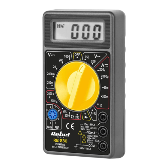
  • Seite 3: Produktbeschreibung

    11. Vor dem Öffnen des Batteriegehäuses die Messleitungen vom Messkreis und vom Gerät trennen. 12. Die Batterie und Sicherung muss durch eine neue mit derselben Spezifikation ersetzt werden. 13. Manipulieren Sie nicht die internen Schaltkreise des Geräts. Dies kann zu einer Verringerung der Genauigkeit oder zu einer Beschädigung des Geräts führen.
  • Seite 4 Spannung und Polarität wird am Display angezeigt. *Wenn der Messbereich nicht bekannt ist, stellen Sie den Bereich auf den höchsten Wert ein und senken diesen allmählich ab, bis eine genaue Messung erhalten wird. Gleichstrommessung [DC] Verbinden Sie die rote Messleitung mit der VΩmA Buchse.
  • Seite 5 5. Verbinden Sie die Messleitungen mit dem Messkreis. 6. Das Ergebnis wird am Display angezeigt. Diodenmessung Verbinden Sie die rote Messleitung mit der VΩmA Buchse. 2. Verbinden Sie die schwarze Messleitung mit der COM Buchse. 3. Setzen Sie den Drehschalter auf Position 4.
  • Seite 6: Reinigung Und Wartung

    3. Setzen Sie den Drehschalter auf Position 4. Verbinden Sie die Messleitungen mit dem Messkreis. Wenn der Widerstand niedriger als 30 Ω ist, ertönt der Summer. hFE Transistortest Setzen Sie den Drehschalter auf Position hFE. 2. Bestimmen Sie den Transistortyp (PNP oder NPN) und verbinden den Emitter, die Basis und den Kollektor mit den richtigen Buchsen.
  • Seite 7: Technische Daten

    TECHNISCHE DATEN Gleichspannung [DC] Bereich Auflösung Genauigkeit 200 mV 100 µV ±(0,5% + 3) 2000 mV 1 mV 20 V 10 mV ±(0,8% + 5) 200 V 100 mV 1000 V ±(1% + 5) Überlastschutz: 200 V AC für 200 mV Bereich; 1000 V DC oder 750 V für alle Bereiche.
  • Seite 8 Durchgangsprüfung (Nur Modele RB-838 und RB-830BUZ) Bereich Beschreibung Wenn der Widerstand niedriger als 30 Ω ist, ertönt der Summer. Überlastschutz: für 15 Sekunden in Max. 220 V. Gleichstrom [DC] Bereich Auflösung Genauigkeit 200 µA 100 nA 2000 µA 1 µA ±(1,8% + 2) 20 mA 10 µA...
  • Seite 9 200 KΩ 100 Ω ±(1% + 4) 2000 KΩ 1 KΩ • Max. Spannung des offenen Schaltkreises: 3,2 V • Überlastschutz: für 15 Sekunden in Max. 220 V. Temperatur (Nur Modell RB-838) Bereich Auflösung Genauigkeit -40°C ~ 150°C ±(1% + 4) 1°C 150°C ~ 1370°C ±(1,5% + 15)
  • Seite 10: Safety Instructions

    SAFETY INSTRUCTIONS In order to avoid electric shock or other injuries, follow the safety instructions below: Before using the device, inspect the case for any mechanical damage. If the case has cracks or is missing any part, do not use the device. 2.
  • Seite 11: Product Description

    13. Do not tamper with devices internal circuits. This may lead to accuracy decrease or damaging the device. 14. The device is intended for indoors use only. 15. Take out the batteries, if the device is not going to be used for a long time. PRODUCT DESCRIPTION Display...
  • Seite 12 4. Open the measured circuit and connect the test leads in series. 5. The result will appear on the display. Caution: while connected to the 10 A terminal, measurements can last only 15 seconds in a few seconds intervals. Resistance measurement Connect the red test lead to the VΩmA terminal.
  • Seite 13 thermocouple to the COM terminal. 3. Set the rotary switch to °C position. 4. The temperature will be displayed. 5. Maximum measurement of the temperature is 250°C / 482°F. Continuity test (models RB-838 and RB-830BUZ only) Connect the red test lead to the VΩmA terminal. 2.
  • Seite 14: Cleaning And Maintenance

    CLEANING AND MAINTENANCE • Clean the device with soft, slightly damp cloth, without abrasive agents. • To change the battery and the fuse, unscrew two screws from the back of the device. After opening the battery cover, replace the battery (note the polarity) and the fuse.
  • Seite 15 • Average responding calibrated in rms of a sine wave. • Frequency range: 45 Hz ~ 450 Hz • Overload protection: 1000 V DC or 750 V for all ranges. Continuity test (models RB-838 and 830-BUZ only) Range Description If the resistance is lower than 30 Ω, the buzzer will buzz.
  • Seite 16 Resistance Range Resolution Accuracy 200 Ω 0,1 Ω ±(1% + 10) 2000 Ω 1 Ω 20 KΩ 10 Ω ±(1% + 4) 200 KΩ 100 Ω 2000 KΩ 1 KΩ • Max. voltage of open circuit: 3,2 V • Overload protection: for 15 seconds in max. 220 Temperature (model RB-838 only) Range Resolution...
  • Seite 17 English Correct Disposal of This Product (Waste Electrical & Electronic Equipment) (Applicable in the European Union and other European countries with separate collection systems) This marking shown on the product or its literature, indicates that it should not be disposed with other household wastes at the end of its working life.
  • Seite 18 KWESTIE BEZPIECZEŃSTWA W celu uniknięcia porażenia elektrycznego lub innej kontuzji podczas korzystania z urządzenia, należy stosować się do poniższych zasad bezpieczeństwa: Przed rozpoczęciem korzystania z urządzenia należy sprawdzić jego obudowę pod kątem uszkodzeń mechanicznych. Jeżeli obudowa posiada pęknięcia lub braki, nie należy korzystać z urządzenia.
  • Seite 19: Opis Urządzenia

    10. Jeżeli na wyświetlaczu pojawia się komunikat o niskim poziomie baterii, należy wymienić baterię. W przeciwnym wypadku dokładność pomiarów może zostać zmniejszona. 11. Przed otwarciem pokrywy baterii należy odłączyć przewody testowe od mierzonego obwodu oraz od urządzenia. 12. Części zamienne (bateria i bezpiecznik) należy wymieniać...
  • Seite 20 4. Podłączyć przewody pomiarowe do mierzonego obwodu. 5. Włączyć zasilanie mierzonego urządzenia lub ścieżki, a napięcie i polaryzacja pojawią się na wyświetlaczu. *Jeżeli zakres nie jest znany, należy ustawić najwyższy zakres i stopniowo zmniejszać, aż do uzyskania precyzyjnego wyniku. Pomiar prądu DC Podłączyć...
  • Seite 21 4. Jeżeli pomiar rezystancji odbędzie się na ścieżce, należy odłączyć ścieżkę od zasilania oraz rozładować wszystkie kondensatory. 5. Podłączyć przewody pomiarowe do mierzonej ścieżki. 6. Wynik zostanie wyświetlony na wyświetlaczu. Pomiar diody Podłączyć czerwony przewód pomiarowy do gniazda VΩmA. 2. Podłączyć czarny przewód pomiarowy do gniazda COM.
  • Seite 22: Czyszczenie I Konserwacja

    Test ciągłości (tylko modele RB-838, RB-830BUZ) Podłączyć czerwony przewód pomiarowy do gniazda VΩmA. 2. Podłączyć czarny przewód pomiarowy do gniazda COM. 3. Ustawić przełącznik wyboru trybu do pozycji 4. Podłączyć przewody pomiarowe do mierzonego obwodu. Jeżeli rezystancja jest mniejsza niż 30 Ω, głośnik wyda dźwięk.
  • Seite 23: Specyfikacja

    • Aby wymienić baterię i bezpiecznik, należy wykręcić dwie śruby z tyłu urządzenia. Po otwarciu pokrywy, można wymienić baterie (zwracając uwagę na poprawność polaryzacji) i bezpiecznik. Po wymianie należy zamknąć pokrywę i przykręcić dwie śruby. SPECYFIKACJA Napięcie DC Zakres Rozdzielczość Dokładność...
  • Seite 24 • Prawidłowy pomiar napięcia przy przebiegu sinusoidalnym. • Zakres częstotliwości: 45 Hz ~ 450 Hz • Zabezpieczenie przed przeciążeniem: 1000 V DC lub 750 V dla pozostałych zakresów. Ciągłość obwodu (tylko modele RB-838, RB-830BUZ) Zakres Opis Wbudowany głośnik wyda dźwięk, jeżeli rezystancja jest mniejsza niż...
  • Seite 25 Rezystancja Zakres Rozdzielczość Dokładność 200 Ω 0,1 Ω ±(1% + 10) 2000 Ω 1 Ω 20 KΩ 10 Ω ±(1% + 4) 200 KΩ 100 Ω 2000 KΩ 1 KΩ • Maksymalne napięcie otwartego obwodu: 3,2 V • Ochrona przed przeciążeniem: przez 15 sekund przy maksimum 220 V.
  • Seite 26 Poland Prawidłowe usuwanie produktu (zużyty sprzęt elektryczny i elektroniczny) Oznaczenie umieszczone na produkcie lub w odnoszących się do niego tekstach wskazuje, że po upływie okresu użytkowania nie należy usuwać z innymi odpadami pochodzącymi z gospodarstw domowych. Aby uniknąć szkodliwego wpływu na środowisko naturalne i zdrowie ludzi wskutek niekontrolowanego usuwania odpadów, prosimy o oddzielenie produktu od innego typu odpadów oraz odpowiedzialny recykling w celu promowania ponownego użycia zasobów materialnych jako stałej...
  • Seite 27: Instrucțiuni Privind Siguranța

    INSTRUCȚIUNI PRIVIND SIGURANȚA Pentru a evita un posibil șoc electric sau vătămare corporală, și pentru a evita posibilele deteriorări ale multimetrului și ale echipamentului testat, respectați următoarele reguli: Înainte de a utiliza multimetrul, verificați carcasa. Nu utilizați multimetrul dacă carcasa este crăpată sau dacă...
  • Seite 28: Descrierea Produsului

    afectată precizia măsurării și măsurătorile pot fi eronate. 11. Înainte de a deschide carcasa bateriei, deconectați sondele de testare de la circuitul măsurat și de la dispozitiv. 12. Piesele de schimb (bateria și siguranța) trebuie înlocuite cu altele noi care au aceleași specificații.
  • Seite 29 4. Conectați cablurile de testare la circuitul măsurat. 5. Porniți alimentarea circuitelor. Tensiunea și polaritatea vor fi afișate pe ecran. *Dacă intervalul nu este cunoscut, setați intervalul cel mai mare și coborâți treptat, până când obțineți măsurarea exactă. Măsurare curent DC Conectați cablul roșu de testare la terminalul VΩmA.
  • Seite 30 4. Dacă măsurarea rezistenței va fi efectuată pe circuit, deconectați circuitul de la alimentare și decuplați toți condensatorii. 5. Conectați cablurile de testare la circuitul măsurat. 6. Rezultatul va fi afișat pe ecran. Măsurare diode Conectați cablul roșu de testare la terminalul VΩmA.
  • Seite 31: Curățare Și Întreținere

    2. Conectați cablul negru de testare la terminalul COM. 3. Setați comutatorul rotativ în poziția 4. Conectați cablurile de testate la circuitul măsurat. Dacă rezistența este mai mică de 30 Ω, va suna alarma. Test tranzistor hFE Setați comutatorul rotativ în poziția hFE. 2.
  • Seite 32 SPECIFICAȚII Tensiune DC Nivel Rezoluție Precizie 200 mV 100 µV ±(0,5% + 3) 2000 mV 1 mV 20 V 10 mV ±(0,8% + 5) 200 V 100 mV 1000 V ±(1% + 5) Protecție la suprasarcină: 200 V AC pentru domeniul 200 mV;...
  • Seite 33 Test continuitate (doar pentru modelele RB-838 și RB-830BUZ) Nivel Descriere Dacă rezistența este mai mică de 30 Ω, va suna alarma. Protecție la suprasarcină: timp de 15 secunde max. Curent DC Nivel Rezoluție Precizie 200 µA 100 nA 2000 µA 1 µA ±(1,8% + 2) 20 mA...
  • Seite 34 Rezistență Nivel Rezoluiție Precizie 200 Ω 0,1 Ω ±(1% + 10) 2000 Ω 1 Ω 20 KΩ 10 Ω ±(1% + 4) 200 KΩ 100 Ω 2000 KΩ 1 KΩ • Tensiunea max. a circuitului deschis: 3,2 V • Protecție la suprasarcină: timp de 15 secunde max.
  • Seite 35 Romania Reciclarea corecta a acestui produs (reziduuri provenind din aparatura electrica si electronica) Marcajale de pe acest produs sau mentionate in instructiunile sale de folosire indica faptul ca produsul nu trebuie aruncat impreuna cu alte reziduuri din gospod arie atunci cand nu mai este in stare de functionare. Pentru a preveni posibile efecte daunatoare asupra mediului inconjurator sau a san ata tii oamenilor datorate evacuarii necontrolate a reziduurilor, vă...
  • Seite 36 www.rebelelectro.com...

Diese Anleitung auch für:

Mie-rb-838Mie-rb-830buz

Inhaltsverzeichnis