Inhaltsverzeichnis
Werbung
Verfügbare Sprachen
Verfügbare Sprachen
Quicklinks
All manuals and user guides at all-guides.com
Betriebsanleitung
Heizungspumpengruppe
PrimoTherm®
Typ: 180-1 DN 32 Ungemischt
Typ: 180-2 DN 32 mit 3-Wege-Mischer und Stellmotor
Typ: 180-3 DN 32 RTA mit 3-Wege-Mischer und Stellmotor mit thermischen Fest-
wertventil
Copyright 2017 AFRISO-EURO-INDEX GmbH. Alle Rechte vorbehalten.
Lindenstraße 20
74363 Güglingen
Telefon +49 7135-102-0
Service +49 7135-102-211
Telefax +49 7135-102-147
info@afriso.com
Version: 04.2017.0
www.afriso.com
ID: 900.000.0717
Werbung
Inhaltsverzeichnis
Fehlerbehebung

Verwandte Anleitungen für AFRISO PrimoTherm 180-1

Inhaltszusammenfassung für AFRISO PrimoTherm 180-1
- Seite 1 Typ: 180-1 DN 32 Ungemischt Typ: 180-2 DN 32 mit 3-Wege-Mischer und Stellmotor Typ: 180-3 DN 32 RTA mit 3-Wege-Mischer und Stellmotor mit thermischen Fest- wertventil Copyright 2017 AFRISO-EURO-INDEX GmbH. Alle Rechte vorbehalten. Lindenstraße 20 74363 Güglingen Telefon +49 7135-102-0...
- Seite 2 All manuals and user guides at all-guides.com Über diese Betriebsanleitung Über diese Betriebsanleitung Diese Betriebsanleitung beschreibt die Heizpumpengruppe PrimoTherm® „180-1 DN 32“ / „180-2 DN 32“ / „180-3 DN 32 RTA“ (im folgenden auch „Pro- dukt“). Diese Betriebsanleitung ist Teil des Produkts. •...
-
Seite 3: Informationen Zur Sicherheit
All manuals and user guides at all-guides.com Informationen zur Sicherheit Informationen zur Sicherheit Warnhinweise und Gefahrenklassen In dieser Betriebsanleitung finden Sie Warnhinweise, die auf potenzielle Gefahren und Risiken aufmerksam machen. Zusätzlich zu den Anweisungen in dieser Betriebsanleitung müssen Sie alle am Einsatzort des Produktes geltenden Bestimmungen, Normen und Sicherheitsvorschriften beachten. - Seite 4 All manuals and user guides at all-guides.com Informationen zur Sicherheit Zusätzlich werden in dieser Betriebsanleitung folgende Symbole verwendet: Dies ist das allgemeine Warnsymbol. Es weist auf die Gefahr von Verletzungen und Sachschäden hin. Befolgen Sie alle im Zusammenhang mit diesem Warnsymbol beschriebenen Hinweise, um Unfälle mit Todesfolge, Verlet- zungen und Sachschäden zu vermeiden.
- Seite 5 All manuals and user guides at all-guides.com Informationen zur Sicherheit Vorhersehbare Fehlanwendung Das Produkt darf insbesondere in folgenden Fällen und für folgende Zwecke nicht angewendet werden: • Betrieb mit Trinkwasser • Betrieb mit verklebenden, ätzenden oder entzündlichen Medien • Betrieb in Anlagen mit Temperaturen über 110 °C (bespielsweise Solaranlagen) Qualifikation des Personals Arbeiten an und mit diesem Produkt dürfen nur von Fachkräften vorgenom-...
-
Seite 6: Transport Und Lagerung
All manuals and user guides at all-guides.com Transport und Lagerung Transport und Lagerung Das Produkt kann durch unsachgemäßen Transport und Lagerung beschä- digt werden. HINWEIS BESCHÄDIGUNG DES PRODUKTS • Stellen Sie sicher, dass während des Transports und der Lagerung des Pro- dukts die spezifizierten Umgebungsbedingungen eingehalten werden. -
Seite 7: Produktbeschreibung
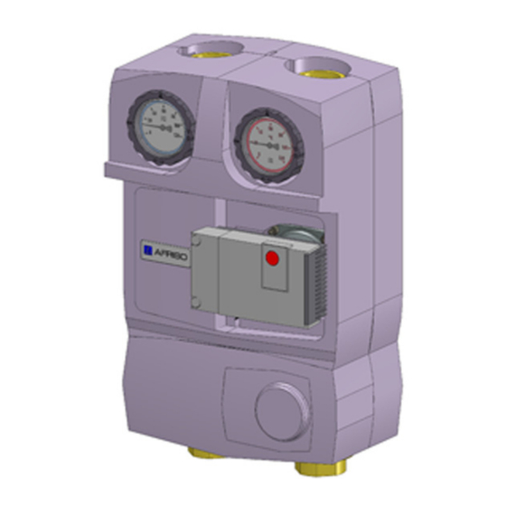
All manuals and user guides at all-guides.com Produktbeschreibung Produktbeschreibung Das Produkt ist eine vormontierte, dichtheitsgeprüfte und wärmegedämmte Heizungspumpengruppe. Das Produkt kann sowohl waagerecht als auch senkrecht montiert werden. Die universelle Isolation erlaubt den Einbau nahezu jeder handelsüblichen Umwälzpumpe ohne großes Nachbearbeiten. Das modulare System ermöglicht zudem die Anordnung des Vorlaufs wahl- weise links oder rechts. - Seite 8 All manuals and user guides at all-guides.com Produktbeschreibung Übersicht A. Kugelhahn, mit Thermo- meter blau B. Wandhalterset komplett mit allen Befestigungstei- C. Kugelhahn, mit Thermo- meter rot D. Umwälzpumpe (optiona- ler Lieferbestandteil) E. Kugelhahn mit Knebelgriff F. EPP Isolation 5-teilig G.
- Seite 9 All manuals and user guides at all-guides.com Produktbeschreibung A. Kugelhahn, mit Thermo- meter blau B. Wandhalterset komplett mit allen Befestigungstei- C. Kugelhahn, mit Thermo- meter rot D. Umwälzpumpe (optiona- ler Lieferbestandteil) E. 3-Wege-Mischer mit Stell- motor ARM343 F. EPP Isolation 5-teilig G.
- Seite 10 All manuals and user guides at all-guides.com Produktbeschreibung A. EPP Isolation 5-teilig B. Rücklaufrohr mit integrier- ter Schwerkraftbremse und T-Stück-Bypass C. Kugelhahn, mit Thermo- meter rot D. Wandhalterset komplett mit allen Befestigungstei- E. Kugelhahn, mit Thermo- meter blau F. Umwälzpumpe (optiona- ler Lieferbestandteil) G.
- Seite 11 All manuals and user guides at all-guides.com Produktbeschreibung Abmessungen und Anschlüsse 250 mm 125 mm Abbildung 4: Beispiel PrimoTherm® 180-1 DN32 180-1 DN 32 / 180-2 DN 32 / 180-3 DN 32 RTA...
- Seite 12 All manuals and user guides at all-guides.com Produktbeschreibung 170 mm 55 mm Abbildung 4: Beispiel PrimoTherm® 180-1 DN32 180-1 DN 32 / 180-2 DN 32 / 180-3 DN 32 RTA...
- Seite 13 All manuals and user guides at all-guides.com Produktbeschreibung Funktion Startbetrieb (Heizen des Kessels) Beim Anheizen des Kessels ist das Kondensationsschutzventil vollständig zum Verbraucher hin geschlossen. Das vom Kessel kommende Heizungs- wasser zirkuliert im kleinen Kreislauf über den Bypass, wodurch die Kes- seltemperatur schnell ansteigt.
- Seite 14 All manuals and user guides at all-guides.com Produktbeschreibung Technische Daten Parameter Wert Allgemeine Daten Abmessungen mit Isolation (B x H x T) 250 x 400 x 170 mm Gewicht Ca. 5,5 kg (je nach Variante, ohne Umwälzpumpe) Werkstoff Armaturen Messing, CU-Rohr Werkstoff Isolation Polypropylen EPP Anlagendruck...
- Seite 15 All manuals and user guides at all-guides.com Produktbeschreibung Parameter Wert Druckverlust gesamt 180-1 DN 32 Kvs = 21,0 m 180-2 DN 32 Kvs = 13,0 m 180-3 DN 32 RTA Kvs = 7,0 m 180-1 DN 32 / 180-2 DN 32 / 180-3 DN 32 RTA...
-
Seite 16: Montage
All manuals and user guides at all-guides.com Montage Montage WARNUNG VERBRENNUNGEN DURCH HEISSE FLÜSSIGKEIT Wasser in Heizungsanlagen steht unter einem hohen Druck und kann Tempe- raturen bis über 100 °C erreichen. • Stellen Sie sicher, dass das Heizwasser abgekühlt ist, bevor Sie die Anlage öffnen und das Produkt montieren. - Seite 17 All manuals and user guides at all-guides.com Montage Stellmotor montieren 1. Entfernen Sie das Handrad. 2. Montieren Sie den Stellmotor gemäß der beiliegenden Anleitung. - Achten Sie hierbei auf die richtige Ausrichtung des Drehschiebers (nur bei PrimoTherm® 180-2 DN 32). Vorlauf/Rücklauf tauschen Falls nicht anders angegeben, beziehen sich alle Angaben in dieser Betriebsanleitung auf die Einbauweise „Vorlauf rechts“.
- Seite 18 All manuals and user guides at all-guides.com Montage Mischer umbauen (nur bei PrimoTherm® 180-2 DN 32) 4. Entfernen Sie die vier Schrauben (E). 5. Ziehen Sie den Dreh- schieber (G) und den Deckel (F) heraus. 6. Vertauschen Sie den Drehschieber (G) und den Deckel (F).
-
Seite 19: Mechanische Belastung Und Verspannung
All manuals and user guides at all-guides.com Montage 8. Ziehen Sie die Überwurf- muttern G2 (H) mit 60 Nm 9. Drehen Sie das Umwälz- pumpeneinlegeteil der Isolation (J) und Logo (I) um 180°. 10.Drehen Sie die Abde- ckung des Mischers (K) um 180°. - Seite 20 All manuals and user guides at all-guides.com Montage 5.5.2 Wandmontage HINWEIS MECHANISCHE BELASTUNG UND VERSPANNUNG • Stellen Sie bei der Montage des Produkts an der Wand sicher, dass das Pro- dukt keinen mechanischen Belastungen und Verspannungen ausgesetzt ist. Nichtbeachtung dieser Anweisungen kann zu Sachschäden führen. 1.
- Seite 21 All manuals and user guides at all-guides.com Montage 6. Führen Sie die beilie- gende Metalldübel M8 (D) ein. 7. Drehen Sie die Gewin- destangen M8 (F) ein, so dass ungefähr 110- 130 mm aus der Wand herausstehen. 8. Ziehen Sie die Gewin- destangen (F) mit jeweils mit einer Mutter M8 (E) fest.
- Seite 22 All manuals and user guides at all-guides.com Montage 11.Lassen Sie den Kunst- stoffhalter (J) an den Thermometer-Handrä- dern (L) der Pumpen- gruppe (M) einrasten. 12.Stecken Sie das Produkt mit dem Kunststoffhalter (J) auf die Gewindestan- gen (H). 13.Bringen Sie dabei die vor- justierten Muttern M8 (I) auf die gewünschte Posi- tion, entsprechend dem...
- Seite 23 All manuals and user guides at all-guides.com Montage 15.Verbinden und verschrauben Sie die Rohrleitungen des Heizkreises mit den Anschlüssen der Armaturen spannungsfrei. 16.Setzten Sie die obere Isolation auf. 180-1 DN 32 / 180-2 DN 32 / 180-3 DN 32 RTA...
-
Seite 24: Elektrischer Schlag
All manuals and user guides at all-guides.com Montage Elektrischer Anschluss GEFAHR ELEKTRISCHER SCHLAG • Stellen Sie sicher, dass durch die Art der elektrischen Installation der Schutz gegen elektrischen Schlag (Schutzklasse, Schutzisolierung) nicht vermin- dert wird. Nichtbeachtung dieser Anweisungen führt zu Tod oder schweren Verlet- zungen. - Seite 25 All manuals and user guides at all-guides.com Inbetriebnahme Inbetriebnahme Produkt in Betrieb nehmen Stellen Sie sicher, dass die Thermometer-Kugelhähne vollständig geöff- net sind. 1. Führen Sie eine Druckprobe durch. 2. Prüfen Sie alle Rohrverschraubungen auf Dichtheit. 3. Bringen Sie zum Befüllen der Anlage die Kugelhähne in 45°-Stellung, sofern ein Rückflussverhinderer in den Kugelhähnen eingebaut sind.
-
Seite 26: Betrieb
All manuals and user guides at all-guides.com Betrieb Betrieb Ein einwandfreier Betrieb ist nur bei offenen Thermometer-Kugelhähnen und Kugelhähnen möglich. Wartung Wartungsintervalle Zeitpunkt Tätigkeit 1 x monatlich Prüfen Sie die Heizungsanlage visuell auf Undichtigkeit. Bei Bedarf Tauschen Sie die Umwälzpumpe aus. Wartungstätigkeiten GEFAHR ELEKTRISCHER SCHLAG DURCH SPANNUNGSFÜHRENDE TEILE... -
Seite 27: Wartung
All manuals and user guides at all-guides.com Wartung 8.2.1 Defekte Umwälzpumpe austauschen (bei Ausführung 180-1 DN 32) 1. Entfernen Sie das Anschlusskabel. 2. Schließen Sie beide Thermometer-Kugelhähne. 3. Schalten Sie das Produkt drucklos. 4. Entleeren Sie das Produkt unterhalb der Kugelhähne. 5. - Seite 28 All manuals and user guides at all-guides.com Wartung 8.2.2 Defekte Umwälzpumpe austauschen (bei Ausführung 180-2 DN 32 und 180-3 DN 32 RTA) 1. Entfernen Sie das Anschlusskabel. 2. Schließen Sie beide Thermometerkugelhähne. 3. Schalten Sie das Produkt drucklos. 4. Entleeren Sie das Produkt unterhalb der Kugelhähne. 5.
-
Seite 29: Störungsbeseitigung
Luft in der Anlage Entlüften Sie die Anlage sche Umwälzpumpe ist falsch Überprüfen Sie die Ein- eingestellt stellung der Umwälz- pumpe Sonstige Störungen Bitte wenden Sie sich an die AFRISO-Service Hotline 180-1 DN 32 / 180-2 DN 32 / 180-3 DN 32 RTA... -
Seite 30: Außerbetriebnahme Und Entsorgung
Vor einer Rücksendung Ihres Produkts müssen Sie sich mit uns in Verbin- dung setzen. Gewährleistung Informationen zur Gewährleistung finden Sie in unseren Allgemeinen Geschäftsbedingungen im Internet unter www.afriso.com oder in Ihrem Kauf- vertrag. 180-1 DN 32 / 180-2 DN 32 / 180-3 DN 32 RTA... -
Seite 31: Ersatzteile Und Zubehör
All manuals and user guides at all-guides.com Ersatzteile und Zubehör Ersatzteile und Zubehör Produkt Artikelbezeichnung Art.-Nr. Abbildung PrimoTherm® 180-1 DN 32 77550 OM OP G1¼ ohne Umwälzpumpe PrimoTherm® 180-1 DN 32 77551 OM WP02 G1¼, mit WILO Stratos PARA 30/1-7 r. K PrimoTherm®... - Seite 32 Type: 180-1 DN 32 unmixed Type:180-2 DN 32 with 3-way mixer and actuator Type: 180-3 DN 32 RTA with 3-way mixer and actuator with thermal fixed value valve Copyright 2017 AFRISO-EURO-INDEX GmbH. All rights reserved. Lindenstraße 20 74363 Güglingen Telefon+49 7135 102-0...
- Seite 33 All manuals and user guides at all-guides.com About these operating instructions About these operating instructions These operating instructions describe the heating pump assembly Primo- Therm® "180-1 DN 32" / "180-2 DN 32" / "180-3 DN 32 RTA" (also referred to as "product" in these operating instructions. These operating instructions are part of the product.
-
Seite 34: Information On Safety
All manuals and user guides at all-guides.com Information on safety Information on safety Safety messages and hazard categories These operating instructions contain safety messages to alert you to poten- tial hazards and risks. In addition to the instructions provided in these oper- ating instructions, you must comply with all directives, standards and safety regulations applicable at the installation site of the product. - Seite 35 All manuals and user guides at all-guides.com Information on safety Intended use This product may only be used to circulate the following liquids in intrinsically safe, thermal heating systems: • Heating circuit water as per VDI 2035 • Water/glycol mixtures with a maximum admixture of 20 % Any use other than the application explicitly permitted in these operating instructions is not permitted and causes hazards.
- Seite 36 All manuals and user guides at all-guides.com Information on safety Predictable incorrect application The product must never be used in the following cases and for the following purposes: • Use with drinking water • Use with adherent, corrosive or flammable fluids •...
-
Seite 37: Transport And Storage
All manuals and user guides at all-guides.com Transport and storage Transport and storage The product may be damaged as a result of improper transport or storage. NOTICE DAMAGE TO THE PRODUCT • Verify compliance with the specified ambient conditions during transport or storage of the product. -
Seite 38: Product Description
All manuals and user guides at all-guides.com Product description Product description The product is a pre-assembled, tightness-tested and heat-insulated heating pump assembly. The product can be installed vertically or horizontally. The universal insulation allows for the installation of virtually any standard cir- culation pump without major reworking of the insulation. - Seite 39 All manuals and user guides at all-guides.com Product description Overview A. Ball valve, with thermome- ter blue B. Wall bracket kit, complete with all mounting parts C. Ball valve, with thermome- ter red D. Circulation pump (optional component) E. Ball valve with T handle F.
- Seite 40 All manuals and user guides at all-guides.com Product description A. Ball valve, with thermome- ter blue B. Wall bracket kit, complete with all mounting parts C. Ball valve, with thermome- ter red D. Circulation pump (optional component) E. 3-way mixer with actuator ARM343 F.
- Seite 41 All manuals and user guides at all-guides.com Product description A. EPP Insulation, 5 pieces B. Return pipe with inte- grated gravity brake and T piece bypass C. Ball valve, with thermome- ter red D. Wall bracket kit, complete with all mounting parts E.
- Seite 42 All manuals and user guides at all-guides.com Product description Dimensions and connections 250 mm 125 mm Fig. 4: Example PrimoTherm® 180-1 DN32 180-1 DN 32 / 180-2 DN 32 / 180-3 DN 32 RTA...
- Seite 43 All manuals and user guides at all-guides.com Product description 170 mm 55 mm Fig. 4: Example PrimoTherm® 180-1 DN32 180-1 DN 32 / 180-2 DN 32 / 180-3 DN 32 RTA...
- Seite 44 All manuals and user guides at all-guides.com Product description Function Start mode (heating up of boiler) When the boiler heats up, the condensation protection valve is fully closed in the direction of the consumer. The heating circuit water coming from the boiler is recirculated in the small circuit via the bypass, which causes the boiler temperature to increase more rapidly.
- Seite 45 All manuals and user guides at all-guides.com Product description Technical specifications Parameter Value General specifications Dimensions with insulation (W x H x D) 250 x 400 x 170 mm Weight Approx. 5.5 kg (depending on version, without circulation pump) Material of fittings Brass, CU pipe Insulation material Polypropylene EPP...
- Seite 46 All manuals and user guides at all-guides.com Mounting Mounting WARNING BURNS CAUSED BY HOT LIQUID Water in heating systems is under high pressure and can have temperatures of more than 100 °C. • Verify that the heating water has cooled down before opening the system and mounting the product.
- Seite 47 All manuals and user guides at all-guides.com Mounting Mounting the actuator 1. Remove the hand wheel. 2. Mount the actuator according to the enclosed instructions. - Verify correct alignment of the rotary slide (PrimoTherm® 180-2 DN 32 only). Interchanging flow/return Unless otherwise specified, all information in these operating instructions relates to the installation type "flow right".
- Seite 48 All manuals and user guides at all-guides.com Mounting Converting the mixer (Primo- Therm® 180-2 DN 32 only) 4. Remove the four screws (E). 5. Pull out the rotary slider (G) and the cover (F). 6. Invert the position of the rotary slider (G) and the cover (F).
- Seite 49 All manuals and user guides at all-guides.com Mounting 8. Tighten the union nuts G2 (H) with a tightening torque of 60 Nm. 9. Turn the insulation part for the circulation pump (J) and the logo (I) by180°. 10.Turn the cover of the mixer (K) by 180°.
- Seite 50 All manuals and user guides at all-guides.com Mounting 5.5.2 Wall mounting NOTICE MECHANICAL LOADS AND STRESS • Verify that the product is not subjected to mechanical loads and stress when mounting the product to the wall. Failure to follow these instructions can result in equipment damage. 1.
- Seite 51 All manuals and user guides at all-guides.com Mounting 6. Insert the two enclosed metal dowels M8 (D). 7. Screw in the threaded rods M8 (F) in such a way that the ends protrude out of the wall by approxi- mately 110-130 mm. 8.
- Seite 52 All manuals and user guides at all-guides.com Mounting 11.Snap the plastic holder (J) onto the hand wheels (L) of the pump assembly (M). 12.Push the product with the plastic holder (J) onto the threaded rods (H). 13.Set the pre-adjusted nuts M8 (I) to the required posi- tion, depending on the necessary wall distance.
- Seite 53 All manuals and user guides at all-guides.com Mounting 15.Connect the pipes of the heating circuit to the connections of the fittings (no mechanical stress). 16.Fit the upper insulation. 180-1 DN 32 / 180-2 DN 32 / 180-3 DN 32 RTA...
-
Seite 54: Electric Shock
All manuals and user guides at all-guides.com Mounting Electrical connection DANGER ELECTRIC SHOCK • Verify that the degree of protection against electric shock (protection class, double insulation) is not reduced by the type of electrical installation. Failure to follow these instructions will result in death or serious injury. DANGER ELECTRIC SHOCK CAUSED BY LIVE PARTS •... - Seite 55 All manuals and user guides at all-guides.com Commissioning Commissioning Commissioning the product Verify that the thermometer ball valves are fully open. 1. Perform a pressure test. 2. Check all screwed connections for tightness. 3. Set the ball valves to 45° position for filling of the system if a backflow pre- venter is installed in the ball valves.
-
Seite 56: Operation
All manuals and user guides at all-guides.com Operation Operation Proper operation is only possible if the thermometer ball valves and the ball valves are open. Maintenance Maintenance intervals When Activity Monthly Perform a visual inspection of the heating system and verify tightness. If required Replace the circulation pump. -
Seite 57: Maintenance
All manuals and user guides at all-guides.com Maintenance 8.2.1 Replacing a defective circulation pump (version 180-1 DN 32) 1. Remove the connection cable. 2. Close both ball thermometer valves. 3. Unpressurise the product. 4. Drain the product below the ball valves. 5. - Seite 58 All manuals and user guides at all-guides.com Maintenance 8.2.2 Replacing a defective circulation pump (versions 180-2 DN 32 and 180-3 DN 32 RTA) 1. Remove the connection cable. 2. Close both thermometer ball valves. 3. Unpressurise the product. 4. Drain the product below the ball valves. 5.
-
Seite 59: Troubleshooting
Noise in the system Air in the system Vent the system Circulation pump not Verify correct adjust- properly adjusted ment of the circulation pump Other malfunctions Contact the AFRISO service hotline 180-1 DN 32 / 180-2 DN 32 / 180-3 DN 32 RTA... -
Seite 60: Decommissioning / Disposal
Returning the device Get in touch with us before returning your product. Warranty See our terms and conditions at www.afriso.com or your purchase contract for information on warranty. 180-1 DN 32 / 180-2 DN 32 / 180-3 DN 32 RTA... -
Seite 61: Spare Parts And Accessories
All manuals and user guides at all-guides.com Spare parts and accessories Spare parts and accessories Product Product designation Part no. Figure PrimoTherm® 180-1 DN 32 77550 OM OP G1¼ without circulation pump PrimoTherm® 180-1 DN 32 77551 OM WP02 G1¼, with WILO Stratos PARA 30/1-7 r.