Herunterladen Inhalt Inhalt Diese Seite drucken
Emerson AVENTICS PM1 Betriebsanleitung

Emerson AVENTICS PM1 Betriebsanleitung

Elektromechanischer druckschalter
Vorschau ausblenden Andere Handbücher für AVENTICS PM1:
Inhaltsverzeichnis

Werbung

Verfügbare Sprachen
  • DE

Verfügbare Sprachen

  • DEUTSCH, seite 1
All manuals and user guides at all-guides.com
Betriebsanleitung | Operating instructions | Notice d'instruction
Istruzioni per l'uso | Instrucciones de servicio | Bruksanvisning
R412018457-BAL-001-AI
2021-06, Replaces: 2021-01
DE/EN/FR/IT/ES/SV
AVENTICS™ PM1
Elektromechanischer Druckschalter
Electromechanical pressure switch
Manostat électromécanique
Pressostato elettromeccanico
Presostato electromecánico
Elektromekanisk tryckvakt

Werbung

Inhaltsverzeichnis
loading

Inhaltszusammenfassung für Emerson AVENTICS PM1

  • Seite 1 All manuals and user guides at all-guides.com Betriebsanleitung | Operating instructions | Notice d’instruction Istruzioni per l'uso | Instrucciones de servicio | Bruksanvisning R412018457-BAL-001-AI 2021-06, Replaces: 2021-01 DE/EN/FR/IT/ES/SV AVENTICS™ PM1 Elektromechanischer Druckschalter Electromechanical pressure switch Manostat électromécanique Pressostato elettromeccanico Presostato electromecánico Elektromekanisk tryckvakt...
  • Seite 2: Inhaltsverzeichnis

    All manuals and user guides at all-guides.com Inhaltsverzeichnis Zu dieser Dokumentation ........................................Zusätzliche Dokumentationen ......................................Darstellung von Informationen ......................................1.2.1 Warnhinweise ........................................1.2.2 Symbole..........................................Sicherheitshinweise........................................... Bestimmungsgemäße Verwendung....................................Qualifikation des Personals ....................................... Allgemeine Sicherheitshinweise......................................2.3.1 Produkt- und technologieabhängige Sicherheitshinweise ..........................Lieferumfang............................................. Zu diesem Produkt ..........................................
  • Seite 3: Zu Dieser Dokumentation

    All manuals and user guides at all-guides.com 1 Zu dieser Dokumentation 2.1 Bestimmungsgemäße Verwendung Lesen Sie diese Dokumentation vollständig und insbesondere das Kapitel „Sicher- Das Produkt darf erst in Betrieb genommen werden, wenn es in die Maschine/die heitshinweise“ ,bevor Sie mit dem Produkt arbeiten. Anlage, für die es bestimmt ist, eingebaut ist.
  • Seite 4: Zu Diesem Produkt

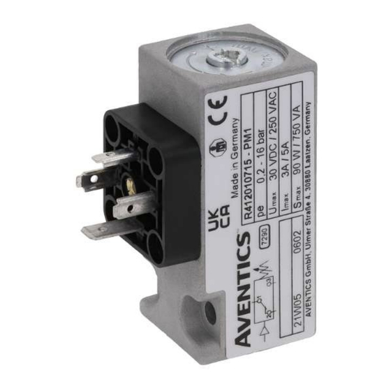
    All manuals and user guides at all-guides.com 4 Zu diesem Produkt Steckanschluss Anschluss G1/4, M  = 12  Nm Gewinde für Zentralschraube M3x35 Einstellschraube zur Feineinstellung, Zulässiges Anzugsdrehmoment selbsthaltend 4.1 Produktbeschreibung = 0,4 +0,1 Der Druckschalter wird verwendet, um bei Erreichen eines zuvor eingestellten Druckwertes einen elektrischen Kontakt zu öffnen bzw.
  • Seite 5: Inbetriebnahme Und Betrieb

    6.1 Druckschalter in Betrieb nehmen Falls Sie den aufgetretenen Fehler nicht beheben konnten, wenden Sie sich bitte an eine der Kontaktadressen unter www.emerson.com/contactus. Zur Inbetriebnahme des Druckschalters gehen Sie wie folgt vor: 1. Prüfen Sie, ob der Druckschalter richtig montiert ist (siehe Kapitel „g 5. Mon- 10.1 Verhalten bei Störungen...
  • Seite 6: Abbildungen

    All manuals and user guides at all-guides.com Schaltvermögen M16x1,5 Schaltspannung [V AC] Stromart Belastungsart max. Schaltstrom [A] Form A Ohmsche Last Induktive Last Ohmsche Last Induktive Last 0,55 0,05 M12x1 Ohmsche Last Induktive Last Ohmsche Last Induktive Last Bezugsschaltzahl 30/min. Bezugstemperatur +30 °C, M12x1, U = 30 V ISO 228 G1/4 Induktive Last: AC = cos ~ 0,7°;...
  • Seite 7 All manuals and user guides at all-guides.com Abb. 6: Form A: Schaltfunktionen Abb. 7: M12x1: Schaltfunktionen Druckschalter Druckschalter Abb. 8: Form A: Schaltfunktionen Vaku- Abb. 9: M12x1: Schaltfunktionen Vaku- umschalter umschalter 1 +UB G1/4 ISO 228 2 Öffner 43,5 3 Schließer 58,6 4 GND Abb. 10: Pin-Belegung für Leitungsdose: Form A 1 +UB 2 Öffner...
  • Seite 8 All manuals and user guides at all-guides.com Contents About This Documentation........................................ Additional documentation ........................................ Presentation of information ......................................1.2.1 Warnings..........................................1.2.2 Symbols ..........................................Notes on Safety ..........................................Intended use ............................................. Personnel qualifications ........................................General safety instructions........................................ 2.3.1 Safety instructions related to the product and technology ..........................Scope of Delivery ..........................................
  • Seite 9: About This Documentation

    All manuals and user guides at all-guides.com • Use is permitted only under the operating conditions and within the perfor- 1 About This Documentation mance limits listed in the technical data. Read this documentation carefully, especially the section “Notes on Safety” , be- •...
  • Seite 10: Overview Of Pressure Switch Form A - Pneumatic Flange Connection

    All manuals and user guides at all-guides.com The contact switches (see g Fig. 6 and g Fig. 7) 5 Assembly • when pressure increases from 1-2 to 1-3 (form A)/from 1-2 to 1-4 (M12x1) - Let the product acclimatize for several hours before commissioning, other- make contact (NO) wise, water may condense in the housing.
  • Seite 11: Commissioning And Operation

    -0.9 – 0 bar / -0.9 – 3 bar / 0.2 – 16 bar tergent! range 7.2 Maintenance Electrics The product is maintenance-free. In case of technical problems, please contact Specifications one of the addresses found under www.emerson.com/contactus. Operating voltage 12 V – 125 V DC; 12 V – 250 V AC min. – max., form A Operating voltage 12 V – 30 V DC/V AC min. – max., M12x1...
  • Seite 12: Figures

    All manuals and user guides at all-guides.com Switching capacity M16x1,5 Switching voltage [V AC] Type Current Load type Max. switching current [A] type Form A Resistive load Inductive load Resistive load Inductive load 0.55 0.05 M12x1 Resistive load Inductive load Resistive load Inductive load Reference cycle: 30/min., reference temperature: +30°C, M12x1, U = 30 V ISO 228...
  • Seite 13 All manuals and user guides at all-guides.com Fig. 6: Form A: Pressure switch switch- Fig. 7: M12x1: Pressure switch switch- ing functions ing functions Fig. 8: Form A: Vacuum switch switch- Fig. 9: M12x1: Vacuum switch switch- ing functions ing functions 1 +UB G1/4 ISO 228 2 Break contact (NC) 43,5...
  • Seite 14 All manuals and user guides at all-guides.com Sommaire A propos de cette documentation...................................... Documentations complémentaires....................................Présentation des informations ......................................1.2.1 Mises en garde ........................................1.2.2 Symboles ........................................... Consignes de sécurité ........................................Utilisation conforme ......................................... Qualification du personnel ........................................ Consignes générales de sécurité ....................................... 2.3.1 Consignes de sécurité...
  • Seite 15: Propos De Cette Documentation

    All manuals and user guides at all-guides.com • Toujours transmettre le produit à de tierces personnes accompagné de la no- 1 A propos de cette documentation tice d’instruction respective. Lire entièrement cette documentation et particulièrement le chapitre « Consignes de sécurité » avant de travailler avec le produit. 2.1 Utilisation conforme Cette notice d’instruction contient des informations importantes pour monter, La mise en service du produit n’est autorisée que lorsque celui-ci est entièrement...
  • Seite 16: Propos De Ce Produit

    All manuals and user guides at all-guides.com • 1 connecteur, selon la version (uniquement pour la forme A) Vis de réglage pour l’ajustage précis, à verrouillage • 2 vis de fixation, en cas de version à bride (CNOMO sans vis de fixation) • 1 joint torique, en cas de version à bride (CNOMO sans joint torique) Pour les références, consulter le catalogue en ligne.
  • Seite 17: Exemple De Dispositif Pare-Étincelles

     ≥ I Diode Réseau Diode Charge s’adresser à l’un des centres mentionnés sous www.emerson.com/contactus. Circuit de protection, tension alternative Voir g Fig. 13 Raccorder le maillon RC (E) parallèlement à la charge (consommateur) (F). 8 Démontage et remplacement Valeur de référence pour la sélection du RC : R [Ω] ~ 0,2 R  [Ω] ;...
  • Seite 18: Illustrations

    All manuals and user guides at all-guides.com Système pneumatique M16x1,5 Spécifications Fluide Air comprimé selon ISO 8573-1:2010, (taille de particule max. : 40 µm ; point de rosée sous pression : ≤ 3 °C ; teneur en huile : 40 mg/m3 max.) ; huile hydraulique Plage de pression de -0,9 … 0 bar / -0,9 … 3 bar / 0,2 … 16 bar commutation Système électrique Spécifications Tension de service...
  • Seite 19 All manuals and user guides at all-guides.com Fig. 6: Forme A : fonctions de commu- Fig. 7: M12x1 : fonctions de commuta- tation Manostat tion Manostat Fig. 8: Forme A : fonctions de commu- Fig. 9: M12x1 : fonctions de commuta- tation Vacuostat tion Vacuostat 1 +UB G1/4 ISO 228 2 Contact de travail 43,5...
  • Seite 20 All manuals and user guides at all-guides.com Indice Sulla presente documentazione......................................Documentazione aggiuntiva ......................................Presentazione delle informazioni ...................................... 1.2.1 Avvertenze di sicurezza ...................................... 1.2.2 Simboli..........................................Indicazioni di sicurezza ........................................Utilizzo a norma ..........................................Qualifica del personale ........................................Avvertenze di sicurezza generali......................................2.3.1 Indicazioni di sicurezza sul prodotto e sulla tecnologia ............................
  • Seite 21: Sulla Presente Documentazione

    All manuals and user guides at all-guides.com 1 Sulla presente documentazione 2.1 Utilizzo a norma Leggere questa documentazione in ogni sua parte e in particolare il capitolo “Av- Il prodotto deve essere messo in funzione solo dopo il montaggio nella macchi- vertenze di sicurezza”, prima di adoperare il prodotto.
  • Seite 22: Descrizione Del Prodotto

    All manuals and user guides at all-guides.com 4 Descrizione del prodotto 4.7 Panoramica pressostato con raccordo ad innesto senza connettore – raccordo pneumatico filettatura inter- 4.1 Descrizione del prodotto na G1/4 Il pressostato viene utilizzato per aprire o chiudere un contatto elettrico al rag- Ved.
  • Seite 23: Spegniarco Raccomandato

    7.2 Manutenzione Circuito di protezione tensione alternata Il prodotto è esente da manutenzione. In caso di problemi tecnici rivolgersi a uno degli indirizzi di contatto riportati alla pagina www.emerson.com/contactus. Ved. g Fig. 13 Collegare il componente RC (E) parallelamente al carico (utenze) (F).
  • Seite 24: Specifiche Elettriche

    All manuals and user guides at all-guides.com Pneumatica M16x1,5 Specificazione Fluido Aria compressa secondo ISO 8573-1:2010, (dimensione max. parti- cella : 40 µm; punto di rugiada in pressione : ≤ 3 °C; contenuto di olio: max. 40 mg/m3) olio idraulico Campo pressione di -0,9 … 0 bar / -0,9 … 3 bar / 0,2 … 16 bar commutazione Specifiche elettriche Specificazione...
  • Seite 25 All manuals and user guides at all-guides.com Fig. 6: Forma A: funzioni di commuta- Fig. 7: M12x1: funzioni di commutazio- zione pressostato ne pressostato Fig. 8: Forma A: funzioni di commuta- Fig. 9: M12x1: funzioni di commutazio- zione vacuostato ne vacuostato 1 +UB G1/4 ISO 228 2 Contatto di apertura 43,5...
  • Seite 26 All manuals and user guides at all-guides.com Índice Acerca de esta documentación ......................................Documentación adicional ......................................... Presentación de la información ......................................1.2.1 Indicaciones de advertencia ....................................1.2.2 Símbolos ..........................................Indicaciones de seguridad........................................Utilización conforme a las especificaciones ..................................Cualificación del personal........................................Indicaciones de seguridad generales ....................................
  • Seite 27: Acerca De Esta Documentación

    All manuals and user guides at all-guides.com 1 Acerca de esta documentación 2.1 Utilización conforme a las especificaciones Antes de empezar a trabajar con el producto, lea esta documentación por com- El producto no debe ponerse en funcionamiento hasta que esté montado en la pleto, especialmente el capítulo “Indicaciones de seguridad”.
  • Seite 28: Sobre Este Producto

    All manuals and user guides at all-guides.com 4 Sobre este producto Racor instantáneo Conexión G1/4, M  = 12  Nm Rosca para tornillo central M3x35 Tornillo de ajuste para el ajuste de Par de apriete admisible precisión, con autorretención 4.1 Descripción de producto = 0,4  Nm +0,1...
  • Seite 29: Propuesta Para Extinción De Chispas

    2. Asegure los componentes que se van a conmutar contra reacciones no inten- En caso de que no haya podido solucionar un fallo, diríjase a las direcciones de cionadas y aplique la tensión. contacto que encontrará en www.emerson.com/contactus. 3. Aplique aire comprimido a la instalación. 10.1 Comportamiento ante averías 4.
  • Seite 30: Sistema Eléctrico

    All manuals and user guides at all-guides.com Neumática M16x1,5 Especificación Fluido Aire comprimido según ISO 8573-1:2010, (tamaño máx. de partícu- la: 40 µm; punto de condensación de presión: ≤ 3 °C; contenido de aceite: máx. 40 mg/m3) de aceite hidráulico Gama de presiones de -0,9 … 0 bar / -0,9 … 3 bar / 0,2 … 16 bar conmutación Sistema eléctrico Especificación...
  • Seite 31 All manuals and user guides at all-guides.com Fig. 6: Forma A: funciones de conmuta- Fig. 7: M12x1: funciones de conmuta- ción del presostato ción del presostato Fig. 8: Forma A: funciones de conmuta- Fig. 9: M12x1: funciones de conmuta- ción del presostato ción del presostato 1 +UB G1/4 ISO 228...
  • Seite 32 All manuals and user guides at all-guides.com Innehåll Om denna dokumentation ........................................ Ytterligare dokumentation ....................................... Återgivning av information ....................................... 1.2.1 Varningsinformation ......................................1.2.2 Symboler..........................................Säkerhetsföreskrifter......................................... Avsedd användning........................................... Personalens kvalifikationer........................................ Allmänna säkerhetsföreskrifter ......................................2.3.1 Produkt- och teknikrelaterade säkerhetsföreskrifter............................Leveransomfattning .......................................... Om denna produkt ..........................................Produktbeskrivning...........................................
  • Seite 33: Om Denna Dokumentation

    All manuals and user guides at all-guides.com • Använd endast tryckluft eller hydraulolja som medium. 1 Om denna dokumentation • Håll dig inom de driftförhållande och inom de effektgränser som anges i Läs igenom hela denna dokumentation och särskilt kapitlet tekniska data.
  • Seite 34: Beskrivning Av Användning

    All manuals and user guides at all-guides.com 5 Montering 4.2 Beskrivning av användning Låt produkten acklimatisera sig några timmar före driftstart, eftersom det Ett medium appliceras på tryckvakten vid anslutningen G1/4 eller vid flänsen. När det inställda kopplingstrycket uppnås manövrerar ett membran en mikrobrytare annars kan bildas kondens i huset.
  • Seite 35: Driftstart Och Drift

    6.1 Ta tryckvakten i drift 10 Felsökning och åtgärder Gör så här för att ta tryckvakten i drift: Använd kontaktadresserna som finns på www.emerson.com/contactus om ett fel 1. Kontrollera att tryckvakten är korrekt monterad (se kapitel ”g 5. Montering” inte kan åtgärdas. och kapitel ”g 2. Säkerhetsföreskrifter”) och se till att alla anslutningar på...
  • Seite 36: Bilder

    All manuals and user guides at all-guides.com Kopplingskapacitet M16x1,5 Kopplingsspänning [V AC] Typ av Typ av belastning max. brytström [A] ström Form A Resistiv last Induktiv last Resistiv last Induktiv last 0,55 0,05 M12x1 Resistiv last Induktiv last Resistiv last Induktiv last Referenskopplingstal 30/min.
  • Seite 37 All manuals and user guides at all-guides.com Bild 6: Form A: Kopplingsfunktion Bild 7: M12x1: Kopplingsfunktion tryckvakt tryckvakt Bild 8: Form A: Kopplingsfunktion Bild 9: M12x1: Kopplingsfunktion vakuumvakt vakuumvakt 1 +UB G1/4 ISO 228 2 Öppnande 43,5 3 Slutande 58,6 4 GND Bild 10: Stifttilldelning för anslutningskontakt: Form A 1 +UB 2 Öppnande 3 Ingen funktion...
  • Seite 38 The Emerson logo is a trademark and service mark of Emerson Electric Co. AVENTICS is a mark Further addresses: of one of the Emerson Automation Solutions family of business units. All other marks are pro- www.emerson.com/contactus...

Inhaltsverzeichnis