HYDAC ELECTRONIC EDS 3000 Bedienungsanleitung
Elektronischer druckschalter
Vorschau ausblenden
Andere Handbücher für EDS 3000:
- Bedienungsanleitung (83 Seiten) ,
- Montageanleitung (45 Seiten) ,
- Bedienungsanleitung (64 Seiten)
Inhaltsverzeichnis
Werbung
Verfügbare Sprachen
Verfügbare Sprachen
Quicklinks
Bedienungsanleitung
(Originalanleitung)
User manual
(Translation of original
instructions)
Notice d'utilisation
(Traduction de l'original)
All manuals and user guides at all-guides.com
Elektronischer Druckschalter
Electronic Pressure Switch
Manocontacteur électronique
EDS 3000
Menüführung nach VDMA
Menu navigation according to
VDMA
Menu VDMA
Werbung
Kapitel
Inhaltsverzeichnis

Verwandte Anleitungen für HYDAC ELECTRONIC EDS 3000


Inhaltszusammenfassung für HYDAC ELECTRONIC EDS 3000
- Seite 1 All manuals and user guides at all-guides.com Elektronischer Druckschalter Electronic Pressure Switch Manocontacteur électronique EDS 3000 Menüführung nach VDMA Menu navigation according to VDMA Menu VDMA ...
-
Seite 2: Inhaltsverzeichnis
Fehlermeldung Anschlussbelegung Technische Daten 11.1 EDS 3000 MIT KERAMIK-SENSORZELLE; ABSOLUT- UND RELATIVDRUCK BIS 16 BAR 11.2 EDS 3000 MIT DÜNNFILM DMS-SENSORZELLE; RELATIVDRUCK AB 40 BAR Bestellangaben ... - Seite 3 Abweichungen bei technischen Angaben, Abbildungen und Maßen sind deshalb möglich. Entdecken Sie beim Lesen dieser Dokumentation Fehler oder haben weitere Anregungen und Hinweise, so wenden Sie sich bitte an: HYDAC ELECTRONIC GMBH Technische Dokumentation Hauptstraße 27 66128 Saarbrücken -Deutschland-...
-
Seite 4: Technische Sicherheit
Sachschäden infolge falscher Handhabung des Gerätes zu vermeiden, beachten Sie bitte die folgenden Sicherheitshinweise: • Der EDS 3000 darf nur in einwandfreiem technischem Zustand benutzt werden. • Die Verwendungshinweise sind einzuhalten. • Die Angaben auf dem Typenschild sind zu beachten. -
Seite 5: Funktionen Des Eds 3000
• (Anpassen des EDS 3000 an die jeweilige Applikation) • Menüführung nach Angabe des VDMA Einheitsblatt 24574-1 Montage Der EDS 3000 kann über den Druckanschluss direkt bzw. indirekt mittels Schlauch oder Minimessleitung an einen Hydraulikblock montiert werden (Anzugsdrehmoment siehe Kap. 11 - Technische Daten). Zur optimalen Ausrichtung ist eine Verdrehung um 340°... -
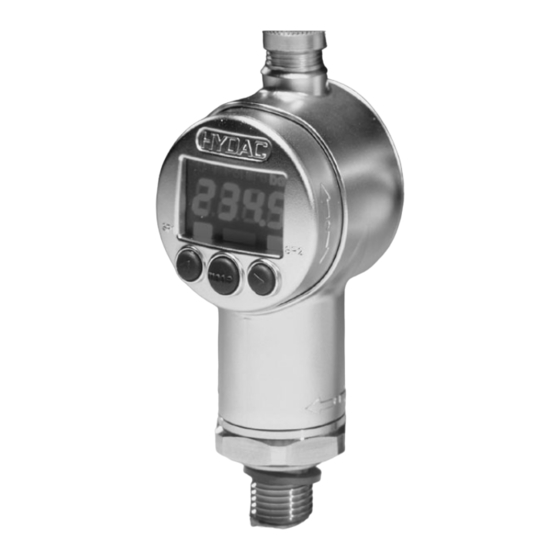
Seite 6: Bedienelemente Des Eds 3000
All manuals and user guides at all-guides.com Bedienelemente des EDS 3000 Mit den Tasten kann zum einen der nächste bzw. vorherige Menüpunkt angewählt werden, zum anderen dienen sie zur Einstellung der Wert. • Im Menü absteigen • Im Menü aufsteigend •... -
Seite 7: Digitalanzeige
All manuals and user guides at all-guides.com Digitalanzeige Nach Einschalten der Versorgungsspannung zeigt das Gerät kurz "EdS" an und beginnt mit der Anzeige des aktuellen Druckes. Darstellung der Digitalanzeige: Darstellung Bezeichnung Darstellung ASCII 7-Segment-Anzeige Schaltpunkt, Ausgang 1 Rückschaltpunkt, Ausgang 1 Schaltpunkt, Ausgang 2 Rückschaltpunkt, Ausgang 2 Druckfenster oberer Wert, Ausgang 1... - Seite 8 All manuals and user guides at all-guides.com Darstellung Bezeichnung Darstellung ASCII 7-Segment-Anzeige Nein Reset Min-/Max-Wert rS.HL rS. k L Programmiersperre Nullpunktkalibrierung cALi CALi Version HINWEISE: • Übersteigt der aktuelle Druck den Nenndruck des Gerätes, so kann er nicht mehr angezeigt werden. In der Anzeige blinkt der Nenndruck. Als Folge blinkt bei Anwählen des Menüpunktes Max-Wert (Hi) der hier gespeicherte Messwert des höchsten gemessenen Druckes bis ein „Reset Min-/Max- Wert“...
-
Seite 9: Ausgangsverhalten
All manuals and user guides at all-guides.com Ausgangsverhalten SCHALTAUSGÄNGE Der EDS 3000 verfügt über 1 bzw. 2 Schaltausgänge. In den Grundeinstellungen kann folgendes Schaltverhalten eingestellt werden: 7.1.1 Einstellung auf Schaltpunkt (SP) Zu jedem Schaltausgang kann ein Schaltpunkt und eine Rückschaltpunkt eingestellt werden. -
Seite 10: Analogausgang
All manuals and user guides at all-guides.com Beispiel für Schaltausgang 1 (Öffner- und Schließerfunktion): Abkürzungen: "FH1", "FH2" = oberer Schaltwert 1 bzw. 2 "FL1", "FL2" = unterer Schaltwert 1 bzw. 2 "FNO" = Schließer bei Fensterfunktion "FNC" = Öffner bei Fensterfunktion HINWEIS: Die Fensterfunktion arbeitet nur dann ordnungsgemäß... -
Seite 11: Menüführung
All manuals and user guides at all-guides.com Menüführung Zur Anpassung an die jeweilige Applikation kann das Verhalten des EDS 3000 über mehrere Einstellungen verändert werden. Diese sind zu einem Menü zusammengefasst. HINWEIS: • Erfolgt ca. 60 Sekunden lang keine Tastenbetätigung, wird das Menü... -
Seite 12: Hauptmenü
All manuals and user guides at all-guides.com Hauptmenü... -
Seite 13: Erweiterte Funktionen
All manuals and user guides at all-guides.com Erweiterte Funktionen... - Seite 14 All manuals and user guides at all-guides.com...
-
Seite 15: Fehlermeldung
All manuals and user guides at all-guides.com Fehlermeldung Wird ein Fehler erkannt, so erscheint eine entsprechende Fehlermeldung, die mit einem beliebigen Tastendruck quittiert werden muss. Mögliche Fehlermeldungen sind: Bei den abgespeicherten Einstellungen wurde ein Datenfehler erkannt. E.10 Mögliche Ursachen sind starke elektromagnetische Störungen oder ein Bauteildefekt. -
Seite 16: Anschlussbelegung
All manuals and user guides at all-guides.com 10 Anschlussbelegung Ausführung mit 1 Schaltausgang: Ausführung mit 1 Schaltausgang und 1 Analogausgang: Stecker 4-pol. M12x1 Stecker 4-pol. M12x1 Ausführung mit 2 Schaltausgängen: Ausführung mit 2 Schaltausgängen und 1 Analogausgang Stecker 4-pol. M12x1 Stecker 5-pol. -
Seite 17: Technische Daten
All manuals and user guides at all-guides.com 11 Technische Daten 11.1 EDS 3000 MIT KERAMIK-SENSORZELLE; ABSOLUT- UND RELATIVDRUCK BIS 16 BAR Eingangsgrößen Messbereiche Keramiksensor Absolutdruck Überlastbereiche Berstdruck Messbereiche Keramiksensor Relativdruck -1 .. 1 1 Überlastbereiche Berstdruck Mechanischer Anschluss G1/4 A ISO1179-2... - Seite 18 All manuals and user guides at all-guides.com Sonstige Größen: Versorgungsspannung 9 .. 35 V ohne Analogausgang 18 .. 35 V mit Analogausgang Bei Einsatz gemäß UL-Spezifikation -limited energy – gemäß 9.3 UL 61010; Class 2; UL 1310/1585; LPS UL 60950 Restwelligkeit Versorgungsspannung ≤...
-
Seite 19: Eds 3000 Mit Dünnfilm Dms-Sensorzelle; Relativdruck Ab 40 Bar
All manuals and user guides at all-guides.com 11.2 EDS 3000 MIT DÜNNFILM DMS-SENSORZELLE; RELATIVDRUCK AB 40 BAR Eingangsgrößen Messbereiche 1000 Überlastbereiche 1000 1600 Berstdruck 1000 2000 2000 3000 Mechanischer Anschluss G1/4 A ISO1179-2 Einschraubloch DIN 3852-G1/4 Anzugsdrehmoment, empfohlen 20 Nm Medienberührende Teile... -
Seite 20: Bestellangaben
All manuals and user guides at all-guides.com 12 Bestellangaben 12.1 EDS 3000 MIT KERAMIK-SENSORZELLE; ABSOLUT- UND RELATIVDRUCK BIS 16 BAR EDS 3 X X X - X - XXXX - V0X - X 1 Ausführung (Technologie) = Keramik absolut = Keramik relativ... -
Seite 21: Eds 3000 Mit Dünnfilm Dms-Sensorzelle; Relativdruck Ab 40 Bar
All manuals and user guides at all-guides.com 12.2 EDS 3000 MIT DÜNNFILM DMS-SENSORZELLE; RELATIVDRUCK AB 40 BAR EDS 3 X X X - X - XXXX - V0X Ausführung (Technologie) = Dünnfilm DMS relativ Anschlussart, mechanisch = G1/4 A ISO1179-2... -
Seite 22: Zubehör
All manuals and user guides at all-guides.com 13 Zubehör 13.1 FÜR DEN ELEKTRISCHEN ANSCHLUSS ZBE 06 (4-pol.) Kupplungsdose M12x1, abgewinkelt Kabeldurchmesser: 2,5 .. 6,5 mm Material-Nr.: 6006788 ZBE 06-02 (4-pol.) Kupplungsdose M12x1, abgewinkelt mit 2 m Leitung, Material-Nr.: 6006790 ZBE 06-05 (4-pol.), Kupplungsdose M12x1, abgewinkelt mit 5 m Leitung Material-Nr.: 6006789... -
Seite 23: Für Den Mechanischen Anschluss
All manuals and user guides at all-guides.com ZBE 08 (5-pol.) Kupplungsdose M12x1, abgewinkelt Kabeldurchmesser: 2,5 .. 6,5 mm Material-Nr.: 6006786 ZBE 08-02 (5-pol.) Kupplungsdose M12x1, abgewinkelt mit 2 m Leitung, Material-Nr.: 6006792 ZBE 08-05 (5-pol.), Kupplungsdose M12x1, abgewinkelt mit 5 m Leitung Material-Nr.: 6006791 Pin 1: braun Farbkennung:... - Seite 24 All manuals and user guides at all-guides.com ZBM 3100 Schelle zur Wandbefestigung, anschweißbar (Werkstoff Schweißlasche: QSTE340TM, galvanischer Überzug EN 12329 FE/ZN8/B; Unterteil: TPE Santoprene 10187; Oberteil: Bandstahl DIN 95381-1.4571) Material-Nr.: 3184632 ZBM 3200 Spritzwasserschutz (Werkstoff: Elastollan S60 A15 SPF 000) Material-Nr.: 3201919...
-
Seite 25: Geräteabmessung
All manuals and user guides at all-guides.com 14 Geräteabmessung G1/4 A ISO 1179-2... - Seite 26 All manuals and user guides at all-guides.com HYDAC ELECTRONIC GMBH Hauptstr. 27 D-66128 Saarbrücken Germany Web: www.hydac.com E-Mail: electronic@hydac.com Tel.: +49 (0)6897 509-01 Fax.: +49 (0)6897 509-1726 HYDAC Service Für Fragen zu Reparaturen steht Ihnen der HYDAC Service zur Verfügung.
- Seite 27 All manuals and user guides at all-guides.com Electronic pressure switch EDS 3000 With menu navigation according to VDMA User manual (Translation of original instructions)
- Seite 28 12.1 EDS 3000 WITH CERAMIC SENSOR CELL; ABSOLUTE AND RELATIVE PRESSURE UP TO 16 BAR 12.2 EDS 3000 WITH THIN FILM DMS SENSOR CELL; RELATIVE PRESSURE STARTING AT 40 BAR Accessories 13.1 FOR ELECTRICAL CONNECTION ...
- Seite 29 Deviations are therefore possible for technical specifications, figures and dimensions. Should you discover errors when reading this document, or if you have any suggestions or remarks, please let us know: HYDAC ELECTRONIC GMBH Technische Dokumentation Hauptstraße 27 66128 Saarbrücken...
-
Seite 30: Technical Safety
• The EDS 3000 must not be put into service if any known defects, either electrical or mechanical, are apparent. • The instructions for use must be strictly adhered to. -
Seite 31: Functions Of The Eds 3000
27) on the hexagon nut of the pressure port. Inappropriate installation methods, such as fitting manually above the housing, can, due to the rotatability of the EDS 3000, damage the housing or even cause the device to fail completely. -
Seite 32: Control Elements Of The Eds 3000
All manuals and user guides at all-guides.com Control elements of the EDS 3000 Indication of pressure unit 4-digit digital display LED indications for active switching point Keys for setting of switching points, switchback points and additional functions buttons can be used to select the next or previous menu options. They can also be used to set values. -
Seite 33: Digital Display
All manuals and user guides at all-guides.com DIgital display Once the power supply has been switched on, the device briefly flashes "EdS", and then begins to show the current pressure. Reading the digital display Designation 7-segment display ASCII Switch point, output 1 Reverse switch point, output 1 Switch point, output 2 Reverse switch point, output 2... - Seite 34 All manuals and user guides at all-guides.com Designation 7-segment display ASCII Reset Min-/Max-value rS.HL rS. k L Programming lock Calibrations of sensors zero point cALi CALi NOTE: • If the current pressure exceeds the device's nominal pressure it can no longer be displayed.
-
Seite 35: Output Behaviour
All manuals and user guides at all-guides.com Output behaviour SWITCHING OUPUTS The EDS 3000 has either 1 or 2 switch outputs. The following switch behaviour can be set in the basic settings: 7.1.1 Set to switch point (SP) A switch point and a reverse switch point can be set for each switching output. The output will switch when the set switch point is reached and switch back when the pressure drops below the reverse switch point. -
Seite 36: Analogue Output
All manuals and user guides at all-guides.com Example for switching output 1 (normally closed and normally open function): Reverse switch point Safety zone Switch point Switch point Safety zone Reverse switch point Normally open function Normally closed function Abbreviations: "FH1", "FH2" = upper switch value 1 / upper switch value 2 "FL1", "FL2"... -
Seite 37: Menu Navigation
All manuals and user guides at all-guides.com Menu navigation A variety of settings can be used to change the behaviour of the EDS 3000 in order to adapt it to the current application. These can be found in a menu. -
Seite 38: Main Menu
All manuals and user guides at all-guides.com Main menu... -
Seite 39: Extended Functions
All manuals and user guides at all-guides.com Extended functions... - Seite 40 All manuals and user guides at all-guides.com...
-
Seite 41: Error Message
All manuals and user guides at all-guides.com Error message If the system detects an error, an error message will be shown. This can be exited by pressing any button. Possible error messages: A data error was detected in the saved settings. This could be due to strong E.10 electromagnetic interference or a defect in a component. -
Seite 42: Wiring Diagrams
All manuals and user guides at all-guides.com 10 Wiring diagrams Design with 1 switching output: Design with 1 switching output and 1 analogue output: Plug: 4 pole, M12x1 Plug: 4 pole, M12x1 Design with 2 switching outputs: Design with 2 switching outputs and 1 analogue output Plug: 4 pole, M12x1 Plug 5 pole, M12x1... -
Seite 43: Technical Specifications
All manuals and user guides at all-guides.com 11 Technical specifications 11.1 EDS 3000 WITH CERAMIC SENSOR CELL; ABSOLUTE AND RELATIVE PRESSURE UP TO 16 BAR Input data Measuring ranges for ceramic sensor at absolute pressure Overload pressures Burst pressure Measuring ranges for -1 .. - Seite 44 All manuals and user guides at all-guides.com Other data Supply voltage 9 .. 35 V without analogue output 18 .. 35 V with analogue output For use acc. to UL spec. -limited energy – according to 9.3 UL 61010; Class 2; UL 1310/1585;...
-
Seite 45: Eds 3000 With Thin Film Dms Sensor Cell; Relative Pressure Starting At 40 Bar
All manuals and user guides at all-guides.com 11.2 EDS 3000 WITH THIN FILM DMS SENSOR CELL; RELATIVE PRESSURE STARTING AT 40 BAR Input data Measuring ranges 1000 Overload pressures 1000 1600 Burst pressure 1000 2000 2000 3000 Mechanical connection G1/4 A ISO1179-2... -
Seite 46: Ordering Details
All manuals and user guides at all-guides.com 12 Ordering details 12.1 EDS 3000 WITH CERAMIC SENSOR CELL; ABSOLUTE AND RELATIVE PRESSURE UP TO 16 BAR EDS 3 X X X - X - XXXX - VXX - X 1 Design (technology) -
Seite 47: Eds 3000 With Thin Film Dms Sensor Cell; Relative Pressure Starting At 40 Bar
All manuals and user guides at all-guides.com 12.2 EDS 3000 WITH THIN FILM DMS SENSOR CELL; RELATIVE PRESSURE STARTING AT 40 BAR EDS 3 X X X - X - XXXX - V0X Design (technology) = Thin film DMS relative... -
Seite 48: Accessories
All manuals and user guides at all-guides.com 13 Accessories 13.1 FOR ELECTRICAL CONNECTION ZBE 06 (4 pole) Female connector M12x1, right-angle Cable diameter: 2,5 .. 6,5 mm Part No.: 6006788 ZBE 06-02 (4 pole) Female connector M12x1, right-angle with 2 m cable Part No.: 6006790 ZBE 06-05 (4pole),... - Seite 49 All manuals and user guides at all-guides.com ZBE 08 (5 pole) Female connector M12x1, right-angle Cable diameter: 2,5 .. 6,5 mm Part No.: 6006786 ZBE 08-02 (5 pole) Female connector M12x1, right-angle with 2 m cable Part No.: 6006792 ZBE 08-05 (5 pole), Female connector M12x1, right-angle with 5 m cable Part No.:...
-
Seite 50: For Mechanical Connection
All manuals and user guides at all-guides.com 13.2 FOR MECHANICAL CONNECTION ZBM 3000 Clip for fastening to wall, screw fitting (Material of lower section: TPE Santoprene 10187; Upper section: Steel strip DIN 95381-1.4571) Part No.: 3184630 ZBM 3100 Clip for fastening to wall, to weld on (Material of welding bridge: QSTE340TM, zinc coating EN 12329 FE/ZN8/B;... -
Seite 51: Device Dimensions
All manuals and user guides at all-guides.com ZBM 3200 Spray protection (Material: Elastollan S60 A15 SPF 000) Material-No.: 3201919 14 Device dimensions Display adjustable 270° Housing adjustable 340° 6hex-SW27 G1/4 A ISO 1179-2 FPM- / EPDM seal Diameter connector M12x1 4-pole / 5 pole... - Seite 52 All manuals and user guides at all-guides.com HYDAC ELECTRONIC GMBH Hauptstr. 27 D-66128 Saarbrücken Germany Web: www.hydac.com E-Mail: electronic@hydac.com Tel.: +49 (0)6897 509-01 Fax.: +49 (0)6897 509-1726 HYDAC Service For enquiries about repairs or alterations, please contact HYDAC Service. SYSTEMS & SERVICES GMBH HYDAC Hauptstr.
- Seite 53 All manuals and user guides at all-guides.com Manocontacteur électronique EDS 3000 Menu VDMA Notice d’utilisation (Traduction de l’original)
- Seite 54 Exclusion de la garantie Fonctions de l'EDS 3000 Montage Eléments de la face avant de l'EDS 3000 Affichage digital Fonctionnement des sorties Sorties de commutation ...
-
Seite 55: Avant-Propos
Si, lors de la lecture de cette documentation, vous deviez détecter des erreurs ou encore si vous aviez des suggestions ou des remarques, veuillez vous adresser à : HYDAC ELECTRONIC GMBH Documentation technique : Hauptstraße 27 66128 Saarbrücken Allemagne Tél:... -
Seite 56: Introduction
à une mauvaise utilisation de l'appareil, veuillez prendre connaissance des points suivants : • L'EDS 3000 ne doit être mis en service que s'il est dans un état technique et visuel irréprochable. -
Seite 57: Fonctions De L'eds 3000
être relié séparément à la terre (par ex. : câble blindé) ATTENTION : L'EDS 3000 doit être monté avec une clé adaptée (de 27) au niveau du raccord métallique 6 pans Un mauvais montage, comme par exemple le vissage par le corps du capteur, en raison de l'orientation de l'EDS 3000, peut endommager le corps de l'appareil et peut entrainer la destruction du capteur. -
Seite 58: Eléments De La Face Avant De L'eds 3000
All manuals and user guides at all-guides.com Eléments de la face avant de l'EDS 3000 Affichage de l'unité de mesure Affichage 4 digits LED de signalisation de l'état des sorties Touches pour réglage des seuils et fonctions annexes Avec les touches il est possible de sélectionner les valeurs du menu... -
Seite 59: Affichage Digital
All manuals and user guides at all-guides.com Affichage digital Après mise sous tension, l'appareil affiche brièvement “EdS” et commence avec l'affichage de la pression actuelle. Description de l'affichage digital Description Désignation affichage Description ASCII 7 segments Point de commutation, sortie 1 Point de déclenchement, sortie 1 Point de commutation, sortie 2 Point de déclenchement, sortie 2... - Seite 60 All manuals and user guides at all-guides.com Description Désignation affichage Description ASCII 7 segments Affichage RAZ est terminé Fonctions complémentaires Reset valeurs Min-/Max rS.HL rS. k L Verrouillage de programmation Tarage zéro du capteur (calibration) cALi CALi Nouveau Version Remarques: •...
-
Seite 61: Fonctionnement Des Sorties
All manuals and user guides at all-guides.com Fonctionnement des sorties Sorties de commutation L'EDS 3000 dispose d'1 ou 2 sorties de commmutation. Dans le menu de base, plusieurs configurations sont possibles : 7.1.1 Fonction seuil (SP) pour chaque sortie de commutation, il est possible de régler 1 seuil d'enclenchement et de déclenchement. -
Seite 62: Sortie Analogique
All manuals and user guides at all-guides.com Exemple pour sortie de commutation 1 (fonction ouvrante et fermante) Réenclenchement FH1 plus 0,4%PE Rü Sicherheitszone Zone de sécurité Commutation Commutation Sicherheitszone Zone de sécurité Réenclenchement Rü FL1 moins 0,4%PE Fonction fermante Fonction ouvrante Raccourcis: "FH1", "FH2"... -
Seite 63: Menu
All manuals and user guides at all-guides.com Menu Pour s'adapter à toutes les applications, l'EDS 3000 peut être modifié avec les réglages de base. Ceux-ci sont rassemblés dans un menu. REMARQUE: • Si au bout de 60 secondes, aucune touche n'a été appuyée, l'affichage retourne à... -
Seite 64: Menu Principal
All manuals and user guides at all-guides.com Menu principal... -
Seite 65: Fonctions Complémentaires
All manuals and user guides at all-guides.com Fonctions complémentaires... - Seite 66 All manuals and user guides at all-guides.com...
-
Seite 67: Message D'erreur
All manuals and user guides at all-guides.com Message d'erreur Dès que l'appareil détecte une erreur, une information est affichée : celle-ci doit être acquittée avec n'importe quelle touche. Les différents codes d'erreurs sont les suivants: Lors de la sauvegarde des réglages, une erreur a été détectée. Les E.10 sources de pannes peuvent être de fortes perturbations électromagnétiques ou un défaut de construction de l'indicateur. -
Seite 68: Raccordement Électrique
All manuals and user guides at all-guides.com 10 Raccordement électrique Exécution avec 1 sortie de commutation Exécution avec 1 sortie de commutation et 1 sortie analogique Connecteur 4 pôles M12x1 Connecteur 4 pôles M12x1 Exécution avec 2 sorties de commutation Exécution avec 2 sorties de commutation et 1 sortie analogique Connecteur 4 pôles M12x1... -
Seite 69: Caractéristiques Techniques
All manuals and user guides at all-guides.com 11 Caractéristiques techniques 11.1 EDS 3000 AVEC CELLULE CERAMIQUE, PRESSION ABSOLUE ET RELATIVE JUSQU'A 16 BAR Données d'entrée Plages de mesure capteur céramique pression absolue Plages de surcharge Pression d‘éclatement bar 5 Plages de mesure capteur céramique bar -1 .. - Seite 70 All manuals and user guides at all-guides.com Autres valeurs Tension d'alimentation 9 .. 35 V sans sortie analogique 18 .. 35 V avec sortie analogique Pour utilisation selon spécification UL -limited energy – selon 9.3 UL 61010; Class 2; UL 1310/1585; LPS UL 60950 Oscillation résiduelle de la tension d’alim.
-
Seite 71: Eds°3000 Avec Cellule Couche Mince Dms, Pression Relative À Partir De 40 Bar
All manuals and user guides at all-guides.com 11.2 EDS°3000 AVEC CELLULE COUCHE MINCE DMS, PRESSION RELATIVE À PARTIR DE 40 BAR Données d'entrée Plages de mesure 1000 Plage de surcharge 1000 1600 Pression d‘éclatement 1000 2000 2000 3000 Raccordement mécanique G1/4 A ISO1179-2, extérieur (DIN 3852), Femelle DIN 3852-G1/4 Couple de serrage, recommandé... -
Seite 72: Code De Commande
All manuals and user guides at all-guides.com 12 Code de commande 12.1 EDS 3000 AVEC CELLULE CERAMIQUE, PRESSION ABSOLUE ET RELATIVE JUSQU'A 16 BAR EDS 3 X X X - X - XXXX - V0X - X 1 Exécution (technologie) = Céramique absolue... -
Seite 73: Eds°3000 Cellule Couche Mince Dms, Pression Relative À Partir De 40 Bar
All manuals and user guides at all-guides.com 12.2 EDS°3000 CELLULE COUCHE MINCE DMS, PRESSION RELATIVE À PARTIR DE 40 BAR EDS 3 X X X - X - XXXX - V0X Exécution (technologie) = Couche mince relative Raccord mécanique = G1/4 A ISO1179-2 = Femelle DIN 3852-G1/4 Raccord électrique = Embase M12x1, 4 pôles (livré... -
Seite 74: Accessoires
All manuals and user guides at all-guides.com 13 Accessoires 13.1 POUR LE RACCORDEMENT ELECTRIQUE ZBE 06 (4 pôles) Connecteur M12x1, coudé Diamètre de câble: 2,5 .. 6,5 mm Code article: 6006788 ZBE 06-02 (4 pôles) Connecteur M12x1, coudé avec 2 m de câble, Code article: 6006790 ZBE 06-05 (4 pôles) Connecteur M12x1, coudé... - Seite 75 All manuals and user guides at all-guides.com ZBE 08 (5 pôles) Connecteur M12x1, coudé Diamètre de câble: 2,5 .. 6,5 mm Code article: 6006786 ZBE 08-02 (5 pôles) Connecteur M12x1, coudé avec 2 m de câble, Code article: 6006792 ZBE 08-05 (5 pôles), Connecteur M12x1, coudé...
-
Seite 76: Pour Le Raccordement Mecanique
All manuals and user guides at all-guides.com 13.2 POUR LE RACCORDEMENT MECANIQUE ZMB 3000 Collier pour fixation murale, à visser (Matériau partie inférieure : TPE Santoprene 10187; supérieur : acier DIN 95381-1.4571) Code article: 3184630 ZMB 3100 Collier pour fixation murale, à souder (Matériau collier à... -
Seite 77: Dimensions
All manuals and user guides at all-guides.com ZMB 3200 Protection contre les projections d'eau (Matériau : Elastollane S60 A15 SPF 000) Code article: 3201919 14 Dimensions orientation corps 270° orientation corps 340° G1/4 A ISO 1179-2 Joint elastomère DIN 3869 Diamètre∅... - Seite 78 All manuals and user guides at all-guides.com HYDAC ELECTRONIC GMBH Hauptstr. D-66128 Saarbrücken Allemagne Web: www.hydac.com E-Mail: electronic@hydac.com Tel.: +49 (0)6897 509-01 Fax.: +49 (0)6897 509-1726 HYDAC Service HYDAC Service se tient à votre disposition pour toute question concernant les réparations.
- Seite 79 All manuals and user guides at all-guides.com Notizen / Notes / Notes ...
- Seite 80 All manuals and user guides at all-guides.com Notizen / Notes / Notes ...