Bernstein 805 Bedienungsanleitung
Toilet installation system
Quicklinks

Verwandte Anleitungen für Bernstein 805


Inhaltszusammenfassung für Bernstein 805
- Seite 1 Installation guide BERNSTEIN Toilet installation system Wellness, Lifestyle & Wohnen...
-
Seite 2: Items Included In The Delivery
Please read this guide carefully before assembling the item! Items included in the delivery: Item Description Indication Quantity Article Description Indication Quantity Rubber seal Ø110 Rawl plug SX10 Ø6-8 Straight flush Screw ST6,8*67 pipe Waste seal Washer Ø22*2,0 Eccentric pipe M12 Bolt Rubber seal Screw cover... - Seite 3 Sound Rubber bolt absorbing panel Flush pipe Screw cover Rubber seal Ø60 Stainless for the flush steel bolt pipe Rawl plug 8*40 Washer Ø11*1,2 Screw ST4,8*45 Items included in the delivery: Aluminium frame Glass panel Flush valve Inlet valve...
- Seite 4 Lever Flush plate Screw set Water cistern Lower half frame Drainage pipe...
-
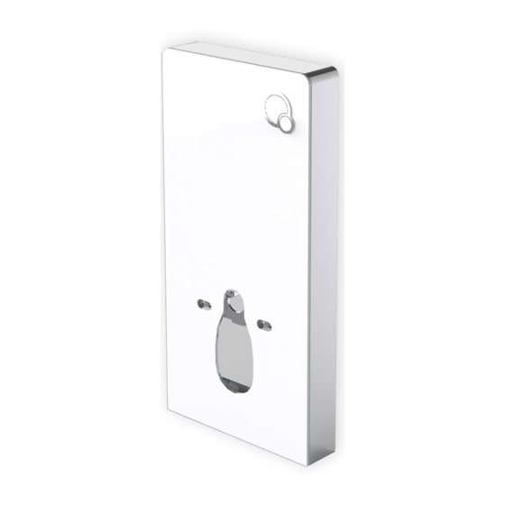
Seite 5: Technical Specifications
Toilet installation system 805 Technical specifications Product type: wall-hung toilet installation system Model: 20981 and 20982 Required room temperature: 3 – 40° C Water supply pressure : 0,07 – 0,75 MPa Water temperature: 4 – 35° C Dimension: 1003,5 x 483 x 108 mm... - Seite 7 Attaching the unit: Insert the drainage pipe into the pre-drilled drainage hole on the wall.
- Seite 8 Remove the upper cover (1) and the support and the support tube (2).
- Seite 9 Put the unit into place against the wall and fix the waste pipe (1) with the hose clamp (2).
- Seite 10 Using a pencil, mark 4 fixing spots on the wall and two fixing spots on the floor – as indicated by the arrows below – (3).
- Seite 11 Loosen the hose clamp and remove the frame from the wall (4).
- Seite 12 Drill the wall according to the pencil marks. The drilling depth has to be larger than the length of the rawl plugs, refer to the diameter indicated in the drawing below (5). Insert the rawl plugs into the corresponding holes (6).
- Seite 13 Position the frame against the wall (7).
- Seite 14 Now fix the unit to the wall tightening the screws in the corresponding rawl plugs (8) and use the bolts to secure the feet on the floor.
- Seite 15 Connect the tube with the support (1) and the corresponding valve on the wall (2 + 3).
- Seite 16 Turn and open the valve on the inlet water pipe (4) in order to assess its functionality.
- Seite 17 Glass panel (4 pieces)
- Seite 18 Fix the glass panel on the alluminium frame of the unit (1). Press the glass buckles downwards (2) until they lock on the alluminium frame.
- Seite 19 Install the flush plate frame (1) and the flush plate (2) fixing them to the glass panel.
- Seite 20 Insert the plugs as shown in the above picture (3).
- Seite 21 blauer Luftschlauch = Tuyau d’air bleu = Blue air hose transparenter Luftschlauch = Tuyau d’air transparent = Trasparent air hose Markierung Teilspülung = Marquage rinçage partiel = Half flush mark Markierung Vollspülung = Marquage rinçage complet = Full flush mark Fix the air hoses as indicated in the above drawing.
- Seite 22 Vorderseite der oberen Abdeckung = Frontal upper cover Linie zum Ausrichten = Reference line Die Rückseite der oberen Abdeckung liegt eng an der Wand an und die Vorderseite eng am Glaspaneel. Beachten Sie, dass die Abdeckung links und rechts anhand der Linien (s. oben) ausgerichtet wird.
- Seite 23 Befestigte Steckvorrichtung an der Seite = Fixed connector on the side Montieren Sie die obere Abdeckung wieder auf das Sanitärmodul. = Reposition the upper cover on the cistern unit Please follow the following steps (16-18) after installing your wall-hung toilet Draw a mark on the straight flush pipe and on the waste pipe (1) Cut the flush pipe and the waste pipe (2)
- Seite 24 Feilen Sie eine Fase/abgeschrägte Kante an die beschnittenen Flächen (3) der beiden Rohre. = File the edge of the pipes 3). Fügen Sie Silikonöl hinzu (4). = Add silicon oil (4).
- Seite 25 Drehen Sie die Bolzen in das Sanitärmodul (1) und befestigen Sie daran die Schallschutzmatte (2). = Fix the screws on the unit (1) and the sound absorbing panel (2)
- Seite 27 Bringen Sie das Abflussrohr an das Sanitärmodul an (3). Fix the waste pipe to the unit (3). Bringen Sie das Spülrohr an das WC an (4). Fix the flush pipe to the wall-hung toilet (4) Montieren Sie das WC an das Sanitärmodul (5). Install the toilet on the frame (5)
- Seite 30 Schneiden Sie die überstehenden Flächen (6) der Schallschutzmatte ab. = Cut the protruding edges (6) of the sound isolation panel...
- Seite 32 Testen Sie die Voll- und Teilspülung (7) Test the half and full flush functions (7)
- Seite 33 INSTANDHALTUNG UND REGELMÄSSIGE PFLEGE: MAINTENANCE: 1.1 Entfernung des Füllventils How to remove the inlet valve Nehmen Sie die obere Abdeckung (1) ab. Lift the upper cover (1)
- Seite 35 Drehen Sie das Absperrventil (2) vom Schlauch ab. Turn off the stop valve (2) on the flexible hose.
- Seite 36 Trennen Sie Schlauch und Ventil (3). Disconnect the hose and the valve (3)
- Seite 37 Entnehmen Sie das Füllventil nach oben (4). Remove the inlet valve pulling it upwards (4)
- Seite 38 1.2 Einstellung und Reinigung des Füllventils Bewegen Sie den Schwimmer (1) nach oben, um die Einfließende Wassermenge zu erhöhen bzw. nach unten, um sie zu verringern. 1.2 Adjustment and cleaning of the inlet valve Lift the float (1) upwards to increase the waterflow or downwards to reduce it.
- Seite 39 Nehmen Sie den Wasserstop ab (2+3) und reinigen Sie ihn (4). Remove the stop valve (2+3) and clean it et nettoyez-la (4).
- Seite 43 1.3 Installation des Füllventils 1.3 Installing the inlet valve Siehe Anweisungen 1 bis 3 in den Zeichnungen. Follow the 1-3 steps on the below drawings.
- Seite 46 2.1 Ausbau des Spülventils 2.1 Removing the flush valve Blauer Luftschlauch = blue air hose Transparenter Luftschlauch = transparent air hose Ziehen Sie die Luftschläuche ab (1). = Disconnect the air hoses (1).
- Seite 47 Bauen Sie den Hebel aus (2). Remove the lever (2)
- Seite 48 Verschlüsse der Aufhängevorrichtung. Buckles oft he hanging cistern...
- Seite 49 Nachdem Sie die Verschlüsse der Aufhängevorrichtung geöffnet haben (3),heben Sie das Spülventil nach oben heraus (4). After opening thebuckles of the hanging cistern (3), lift the flush valve upwards (4).
- Seite 50 2.2 Einstellung und Reinigung des Spülventils 2.2 Setting and cleaning the flush valve Schwimmer = Float Bewegen Sie den Schwimmer (1) nach oben, um die einfließende Wassermenge zu verringern bzw. nach unten, um sie zu erhöhen. Pull the float (1) upwards to decrease the water flow or push it downwards to increase it.
- Seite 51 Abdeckung = Cover Gummidichtung= Joint en caoutchouc Unterlegscheibe = Rondelle Abdeckung = Cache Reinigen Sie die Unterlegscheibe (4). Nettoyez la rondelle (4).
- Seite 52 2.3 Installation des Spülventils 2.3 Installation de la vanne de rinçage...
- Seite 53 Montieren Sie das Spülventil von oben nach unten in das Sanitärmodul (1). Achtung: Die Unterseite des Spülventils muss passend in dessen Sockel eingesetzt werden (2). Beachten Sie dabei, dass das Spülventil wie in der angezeigten Richtung montiert wird. Installez la vanne de rinçage du haut vers le bas dans le module sanitaire (1). Attention: Le dessous de la vanne de rinçage doit-être monté...
- Seite 54 „Klick“ = „Cliquez“ Montieren Sie das Spülventil so weit, bis es in der richtigen Position hörbar einrastet. Press the flush valve until it clicks in the correct position.
- Seite 55 Montieren Sie den Hebel (3). Install the lever (3).
- Seite 56 Befestigen Sie die Glasabdeckung (4). Fix the glass cover (4)