Herunterladen Inhalt Inhalt Diese Seite drucken
MSI B85M-E45 Bedienungsanleitung
Vorschau ausblenden Andere Handbücher für B85M-E45:
Inhaltsverzeichnis

Werbung

Verfügbare Sprachen

Verfügbare Sprachen

Preface
B85M-E45
Motherboard
G52-78171X4

Werbung

Inhaltsverzeichnis
loading

Inhaltszusammenfassung für MSI B85M-E45

  • Seite 1 Preface B85M-E45 Motherboard G52-78171X4...
  • Seite 2: Trademarks

    Copyright Notice The material in this document is the intellectual property of MICRO-STAR INTERNATIONAL. We take every care in the preparation of this document, but no guarantee is given as to the correctness of its contents. Our products are under continual improvement and we reserve the right to make changes without notice.
  • Seite 3: Technical Support

    If a problem arises with your system and no solution can be obtained from the user’s manual, please contact your place of purchase or local distributor. Alternatively, please try the following help resources for further guidance. Visit the MSI website for technical guide, BIOS updates, driver updates, and other information: http://www.msi.com/service/download/ Contact our technical staff at: http://support.msi.com...
  • Seite 4: Safety Instructions

    Safety Instructions ■ Always read the safety instructions carefully. ■ Keep this User’s Manual for future reference. ■ Keep this equipment away from humidity. ■ Lay this equipment on a reliable flat surface before setting it up. ■ The openings on the enclosure are for air convection hence protects the equipment from overheating.
  • Seite 5: Fcc-B Radio Frequency Interference Statement

    FCC-B Radio Frequency Interference Statement This equipment has been tested and found to comply with the limits for a Class B digital device, pursuant to Part 15 of the FCC Rules. These limits are designed to provide reasonable protection against harmful interference in a residential installation. This equipment generates, uses and can radiate radio frequency energy and, if not installed and used in accordance with the instructions, may cause harmful interference to radio communications.
  • Seite 6 Radiation Exposure Statement This equipment complies with FCC radiation exposure limits set forth for an uncontrolled environment. This equipment and its antenna should be installed and operated with minimum distance 20 cm between the radiator and your body. This equipment and its antenna must not be co-located or operating in conjunction with any other antenna or transmitter.
  • Seite 7: Battery Information

    Replace only with the same or equivalent type recommended by the manufacturer. Chemical Substances Information In compliance with chemical substances regulations, such as the EU REACH Regulation (Regulation EC No. 1907/2006 of the European Parliament and the Council), MSI provides the information of chemical substances in products at: http://www.msi.com/html/popup/csr/evmtprtt_pcm.html Preface...
  • Seite 8: Weee (Waste Electrical And Electronic Equipment) Statement

    MSI will comply with the product take back requirements at the end of life of MSI-branded products that are sold into the EU. You can return these products to local collection points.
  • Seite 9 MSI će poštovati zahtev o preuzimanju ovakvih proizvoda kojima je istekao vek trajanja, koji imaju MSI oznaku i koji su prodati u EU. Ove proizvode možete vratiti na lokalnim mestima za prikupljanje.
  • Seite 10 MSI si adeguerà a tale Direttiva ritirando tutti i prodotti marchiati MSI che sono stati venduti all’interno dell’Unione Europea alla fine del loro ciclo di vita.
  • Seite 11: Inhaltsverzeichnis

    CONTENTS ▍ English ...................... En-1 Motherboard Specifications ................En-2 Connectors Quick Guide ..................En-4 Back Panel Quick Guide ..................En-6 CPU (Central Processing Unit) ................En-8 Memory ......................En-12 Mounting Screw Holes ..................En-13 Power Supply ....................En-14 Expansion Slots ....................En-15 Video/ Graphics Cards ..................En-16 Internal Connectors ..................En-17 Jumper ......................En-23 Drivers and Utilities ..................En-24 BIOS Setup ......................En-25...
  • Seite 12 Emplacements d’extension ................Fr-15 Cartes Vidéo/ Graphics ..................Fr-16 Connecteurs internes ..................Fr-17 Cavaliers ......................Fr-23 Pilotes et Utilitaires ....................Fr-24 Configuration BIOS ...................Fr-25 Русский ....................Ru-1 Характеристики системной платы..............Ru-2 Краткое руководство по разъемам ..............Ru-4 Краткое руководство по работе с задней панелью ........Ru-6 ЦП...
  • Seite 13: English

    English Thank you for choosing the B85M-E45 Series (MS-7817 v2.X) Micro-ATX motherboard. The B85M-E45 Series motherboards are based on Intel ® chipset for optimal system efficiency. Designed to fit the advanced Intel ® LGA1150 processor, the B85M-E45 Series motherboards deliver a high...
  • Seite 14: Motherboard Specifications

    Motherboard Specifications ■ 4th Generation Intel Core™ i7 / Core™ i5 / Core™ i3 / Pentium ® ® Celeron processors for LGA 1150 socket Support ® Chipset ■ Intel B85 Express Chipset ® Memory ■ 4x DDR3 memory slots supporting up to 32GB ■...
  • Seite 15 Internal ■ 1x 24-pin ATX main power connector ■ 1x 4-pin ATX 12V power connector Connectors ■ 4x SATA 6Gb/s connectors ■ 2x SATA 3Gb/s connectors ■ 2x USB 2.0 connectors (supports additional 4 USB 2.0 ports) ■ 1x USB 3.0 connector (supports additional 2 USB 3.0 ports) ■...
  • Seite 16: Connectors Quick Guide

    Connectors Quick Guide DIMM4 CPUFAN SYSFAN2 DIMM3 DIMM2 JPWR1 DIMM1 CPU Socket JCOM1 Back Panel SYSFAN1 JPWR2 PCI_E1 JCI1 JBAT1 PCI_E2 SATA2 SATA5_6 PCI_E3 JTPM1 JUSB3 PCI1 SATA1 JAUD1 SATA3 JUSB1 SATA4 JLPT1 JUSB2 JFP1 JFP2 En-4...
  • Seite 17 PCI_E2, PCI_E3 PCIe x1 Expansion Slots En-15 PCI1 PCI Expansion Slot En-15 SATA1~4 SATA 6Gb/s Connectors En-17 SATA5~6 SATA 3Gb/s Connectors En-17 For the latest information about CPU, please visit http://www.msi.com/service/cpu-support/ For more information on compatible components, please visit http://www.msi.com/service/test-report/ En-5...
  • Seite 18: Back Panel Quick Guide

    Back Panel Quick Guide LAN Port VGA Port Line-In PS/2 Mouse Port USB 2.0 Port Line-Out HDMI USB 3.0 Port DVI-D Port USB 2.0 Port PS/2 Keyboard Port ▶ PS/2 Keyboard/Mouse Port The PS/2 mouse/keyboard DIN connectors for a PS/2 mouse/keyboard.
  • Seite 19 Important This platform supports dual-display and triple-display function. HDMI+VGA VGA+DVI-D DVI-D+HDMI HDMI+VGA+DVI-D Extend mode ◯ ◯ ◯ ◯ (Extend the desktop to the second and third monitor) Clone mode ◯ ◯ ◯ ◯ (Monitors have the same screen) ▶ LAN Port The standard RJ-45 LAN jack is for connecting to a Local Area Network (LAN).
  • Seite 20: Cpu (Central Processing Unit)

    This motherboard is designed to support overclocking. Before attempting to overclock, please make sure that all other system components can tolerate overclocking. Any attempt to operate beyond product specifications is not recommend. MSI does not guarantee the damages or risks caused by inadequate operation beyond product specifications.
  • Seite 21: Cpu & Heatsink Installation

    CPU & Heatsink Installation When installing a CPU, always remember to install a CPU heatsink. A CPU heatsink is necessary to prevent overheating and maintain system stability. Follow the steps below to ensure correct CPU and heatsink installation. Wrong installation can damage both the CPU and the motherboard.
  • Seite 22 3. Align the notches with the socket alignment keys. Lower the CPU straight down, without tilting or sliding the CPU in the socket. Inspect the CPU to check if it is properly seated in the socket. 4. Close and slide the load plate under the retention knob. Close and engage the load lever.
  • Seite 23 7. Locate the CPU fan connector on the motherboard. 8. Place the heatsink on the motherboard with the fan’s cable facing towards the fan connector and the fasteners matching the holes on the motherboard. CPU fan connector 9. Push down the heatsink until the four fasteners get wedged into the holes on the motherboard.
  • Seite 24: Memory

    Memory These DIMM slots are used for installing memory modules. For more information on compatible components, please visit http://www.msi.com/service/test-report/ DIMM1 DIMM2 DIMM3 DIMM4 Video Demonstration Watch the video to learn how to install memories at the address below. http://youtu.be/76yLtJaKlCQ Dual-Channel mode Population Rule In Dual-Channel mode, the memory modules can transmit and receive data with two data bus channels simultaneously.
  • Seite 25: Mounting Screw Holes

    Mounting Screw Holes When installing the motherboard, first install the necessary mounting stands required for an motherboard on the mounting plate in your computer case. If there is an I/O back plate that came with the computer case, please replace it with the I/O backplate that came with the motherboard package.
  • Seite 26: Power Supply

    Power Supply Video Demonstration Watch the video to learn how to install power supply connectors. http://youtu.be/gkDYyR_83I4 JPWR1~2: ATX Power Connectors These connectors allow you to connect an ATX power supply. To connect the ATX power supply, align the power supply cable with the connector and firmly press the cable into the connector.
  • Seite 27: Expansion Slots

    Expansion Slots This motherboard contains numerous slots for expansion cards, such as discrete graphics or audio cards. PCI_E1~E3: PCIe Expansion Slots The PCIe slot supports the PCIe interface expansion card. PCIe 3.0 x16 Slot PCIe 2.0 x1 Slot PCI1: PCI Expansion Slot The PCI slot supports additional LAN, SCSI, USB, and other add-on cards that comply with PCI specifications.
  • Seite 28: Video/ Graphics Cards

    Adding on one or more discrete video cards will significantly boost the system’s graphics performance. For best compatibility, MSI graphics cards are recommended. Video Demonstration Watch the video to learn how to install a graphics card on PCIe x16 slot with butterfly lock.
  • Seite 29: Internal Connectors

    Internal Connectors SATA1~6: SATA Connectors This connector is a high-speed SATA interface port. Each connector can connect to one SATA device. SATA devices include disk drives (HDD), solid state drives (SSD), and optical drives (CD/ DVD/ Blu-Ray). Video Demonstration Watch the video to learn how to Install SATA HDD. http://youtu.be/RZsMpqxythc SATA6 SATA4...
  • Seite 30 CPUFAN,SYSFAN1~2: Fan Power Connectors The fan power connectors support system cooling fans with +12V. If the motherboard has a System Hardware Monitor chipset on-board, you must use a specially designed fan with a speed sensor to take advantage of the CPU fan control. Remember to connect all system fans.
  • Seite 31 JFP1, JFP2: System Panel Connectors These connectors connect to the front panel switches and LEDs. The JFP1 connector is compliant with the Intel Front Panel I/O Connectivity Design Guide. When ® installing the front panel connectors, please use the optional M-Connector to simplify installation.
  • Seite 32 JUSB1~2: USB 2.0 Expansion Connector This connector is designed for connecting high-speed USB peripherals such as USB HDDs, digital cameras, MP3 players, printers, modems, and many others. Important Note that the VCC and GND pins must be connected correctly to avoid possible damage.
  • Seite 33: Jci1: Chassis Intrusion Connector

    JCI1: Chassis Intrusion Connector This connector connects to the chassis intrusion switch cable. If the computer case is opened, the chassis intrusion mechanism will be activated. The system will record this intrusion and a warning message will flash on screen. To clear the warning, you must enter the BIOS utility and clear the record.
  • Seite 34: Jtpm1: Tpm Module Connector

    JTPM1: TPM Module Connector This connector connects to a optional TPM (Trusted Platform Module) Module. Please refer to the TPM security platform manual for more details and usages. JLPT1: Parallel Port Connector This connector is used to connect an optional parallel port bracket. The parallel port is a standard printer port that supports Enhanced Parallel Port (EPP) and Extended Capabilities Parallel Port (ECP) mode.
  • Seite 35: Jcom1: Serial Port Connector

    JCOM1: Serial Port Connector This connector is a 16550A high speed communication port that sends/receives 16 bytes FIFOs. You can attach a serial device. Jumper JBAT1: Clear CMOS Jumper There is CMOS RAM onboard that is external powered from a battery located on the motherboard to save system configuration data.
  • Seite 36: Drivers And Utilities

    After you install the operating system you will need to install drivers to maximize the performance of the new computer you just built. MSI motherboard comes with a Driver Disc. Drivers allow the computer to utilize your motherboard more efficiently and take advantage of any special features we provide.
  • Seite 37: Bios Setup

    Click "GO2BIOS" tab on "MSI Fast Boot" utility screen. Important Please be sure to install the “MSI Fast Boot” utility before using it to enter the BIOS • setup. • The items under each BIOS category described in this chapter are under continuous update for better system performance.
  • Seite 38 Overview After entering BIOS, the following screen is displayed. Temperature monitor Language System information Model name Virtual OC Genie Button Boot device priority bar BIOS menu selection BIOS menu selection Menu display ▶ Temperature monitor Show the temperatures of the processor and the motherboard. ▶...
  • Seite 39 Enables or disables the OC Genie function by clicking on this button. When enabled, this button will be light. Enabling OC Genie function can automatically overclock with MSI optimized overclocking profile. Important We recommend that you do not to make any modification in OC menu and do not to load defaults after enabling the OC Genie function.
  • Seite 40 Operation You can control BIOS settings with the mouse and the keyboard. The following table lists and describes the hot keys and the mouse operations. Hot key Mouse Description <↑↓→← > Select Item Move the cursor <Enter> Select Icon/ Field Click/ Double-click the left button <Esc>...
  • Seite 41 OC Menu This menu is for advanced users who want to overclock the motherboard. Important • Overclocking your PC manually is only recommended for advanced users. Overclocking is not guaranteed, and if done improperly, can void your warranty or • severely damage your hardware.
  • Seite 42 ▶ Intel Turbo Boost [Enabled] Enables or disables the Intel Turbo Boost. This item appears when the installed CPU ® supports this function. [Enabled] Enables this function to boost CPU performance automatically above rated specifications when system request the highest performance state.
  • Seite 43 ▶ DRAM Training Configuration Press <Enter> to enter the sub-menu. Enables or disables the various training ways of DRAM. The system may become unstable or unbootable after changing these items in this sub-menu. If it occurs, please clear the CMOS data and restore the default settings.
  • Seite 44 ▶ CPU Specifications Press <Enter> to enter the sub-menu. This sub-menu displays the information of installed CPU. You can also access this information menu at any time by pressing [F4]. Read only. ▶ CPU Technology Support Press <Enter> to enter the sub-menu. The sub-menu shows what the key features does the installed CPU support.
  • Seite 45 ▶ Hardware Prefetcher [Enabled] Enables or disables the hardware prefetcher (MLC Streamer prefetcher). [Enabled] Allows the hardware prefetcher to automatically pre-fetch data and instructions into L2 cache from memory for tuning the CPU performance. [Disabled] Disables the hardware prefetcher. ▶ Adjacent Cache Line Prefetch [Enabled] Enables or disables the CPU hardware prefetcher (MLC Spatial prefetcher).
  • Seite 46 ▶ LakeTiny Feature [Disabled] Enables or disables Intel Lake Tiny feature with iRST for SSD. This item appears when a installed CPU supports this function and "Intel C-State" is enabled. [Enabled] Enhance the dynamic IO load adjusted performance for accelerating the SSD speed.
  • Seite 47: Deutsch

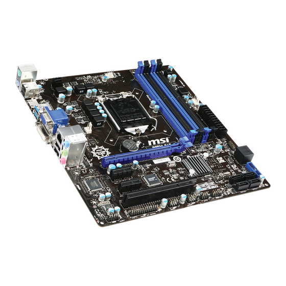
    Diese B85M-E45 Motherboard basiert auf dem Intel ® Chipsatz und ermöglicht so ein optimales und effizientes System. Entworfen, um den hochentwickelten Intel LGA1150 Prozessor zu unterstützen, ® stellt die B85M-E45 die ideale Lösung zum Aufbau eines professionellen Hochleistungsdesktopsystems dar.
  • Seite 48: Spezifikationen

    Spezifikationen Prozessor ■ Die Intel Core™ i7 / Core™ i5 / Core™ i3 / Pentium / Celeron ® ® ® Prozessoren der 4. Generation für LGA 1150 Sockel Chipsatz ■ Intel B85 Express Chipsatz ® Speicher ■ 4x DDR3 Speicherplätze unterstützen bis zu 32GB ■...
  • Seite 49 Interne ■ ATX 24-poliger Stromanschluss x1 ■ ATX12V 4-poliger Stromanschluss x1 Anschlüsse ■ SATA 6Gb/s Anschlüsse x4 ■ SATA 3Gb/s Anschlüsse x2 ■ USB 2.0 Anschlüsse x2 (unterstützt zusätzliche 4 USB 2.0- Ports) ■ USB 3.0 Anschluss x1 (unterstützt zusätzliche 2 USB 3.0-Ports) ■...
  • Seite 50: Anschlussübersicht

    Anschlussübersicht DIMM4 CPUFAN SYSFAN2 DIMM3 DIMM2 JPWR1 DIMM1 CPU Sockel JCOM1 Rücktafel SYSFAN1 JPWR2 PCI_E1 JCI1 JBAT1 PCI_E2 SATA2 SATA5_6 PCI_E3 JTPM1 JUSB3 PCI1 SATA1 JAUD1 SATA3 JUSB1 SATA4 JLPT1 JUSB2 JFP1 JFP2 De-4...
  • Seite 51: Übersicht Der Motherboard-Anschlüsse

    PCIe x16 Erweiterungssteckplatz De-15 PCI_E2, PCI_E3 PCIe x1 Erweiterungssteckplätze De-15 PCI1 PCI Erweiterungssteckplatz De-15 SATA1~4 SATA 6Gb/s Anschlüsse De-17 SATA5~6 SATA 3Gb/s Anschlüsse De-17 Weitere CPU Informationen finden Sie unter http://www.msi.com/service/cpu-support/ Die neusten Informationen über kompatible Bauteile finden Sie unter http://www.msi.com/service/test-report/ De-5...
  • Seite 52: Rücktafel-Übersicht

    Rücktafel-Übersicht PS/2 Tastatur Anschluss VGA Anschluss Line-In Anschluss USB 2.0 Anschluss Line-Out HDMI USB 3.0 DVI-D Anschluss USB 2.0 PS/2 Maus Anschluss Anschluss Anschluss ▶ PS/2 Tastatur/Maus Anschluss Die Standard PS/2 Maus/Tastatur Stecker DIN ist für eine PS/2 Maus/Tastatur. ® ®...
  • Seite 53 Wichtig Diese Plattform unterstützt die Ausgabe über 2- oder 3 Displays. HDMI+VGA VGA+DVI-D DVI-D+HDMI HDMI+VGA+DVI-D Erweiterter-Modus (Erweiterung des Desktops auf ◯ ◯ ◯ ◯ einen zweiten und dritten Monitor) Clone-Modus ◯ ◯ ◯ ◯ (Monitore zeigen das gleiche Bild) ▶ LAN Port Die Standard RJ-45 Buchse dient zur Verbindung in einem lokalen Netzwerk (LAN).
  • Seite 54: Cpu (Prozessor)

    CPU (Prozessor) Erklärung zur LGA 1150 CPU Die Obserseite der LGA 1150 CPU hat zwei Justierungen und ein gelbes Dreieck um die korrekte Ausrichtung der CPU auf dem Motherboard zu gewährleisten. Das gelbe Dreieck des Prozessors definiert die Position des ersten Pins. Kerbe Kerbe Das goldene Dreieck des Prozessors...
  • Seite 55: Cpu & Kühlkörper Einbau

    CPU & Kühlkörper Einbau Wenn Sie die CPU einbauen, denken sie bitte daran einen CPU-Kühler zu installieren. Ein CPU-Kühlkörper ist notwendig, um eine Überhitzung zu vermeiden und die Systemstabilität beizubehalten. Befolgen Sie die nachstehenden Schritte, um die richtige CPU und CPU-Kühlkörper Installation zu gewährleisten. Ein fehlerhafter Einbau führt zu Schäden an der CPU und dem Motherboard.
  • Seite 56 3. Positionieren Sie die Kerben mit die Justiermarkierungen des Sockels. Setzen Sie die CPU nach unten, ohne Kippen oder Schieben der CPU im Sockel. Begutachten Sie, ob die CPU richtig im Sockel sitzt. 4. Schließen Sie und schieben Sie die Abdeckplatte unter dem Rückhalteknopf. Verschließen Sie den Verschlusshebel.
  • Seite 57 7. Machen Sie den CPU-Lüfteranschluss auf dem Motherboard ausfinding. 8. Setzen Sie den Kühlkörper auf die CPU und beachten Sie die Übereinstimmung der Lüfterverankerungen mit den dafür vorgsehenen Löchern auf der Motherboard -Platine. CPU-Lüfteranschluss 9. Drücken Sie nach der korrekten Positionierung des Kühlkörpers die Arretierungsstifte mit leichtem Druck nach unten bis sie einrasten.
  • Seite 58: Speicher

    Speicher Die DIMM-Steckplätze nehmen Arbeitsspeichermodule auf. Die neusten Informationen über kompatible Bauteile finden Sie unter http://www.msi.com/service/test-report/ DIMM1 DIMM2 DIMM3 DIMM4 Video-Demonstration Anhand dieses Video an untenstehende Adresse lernen Sie, wie Sie die Speichermodule installieren. http://youtu.be/76yLtJaKlCQ Populationsregeln für Dual-Kanal-Speicher Im Dual-Kanal-Modus können Arbeitsspeichermodule Daten über zwei Datenbusleitungen gleichzeitig senden und empfangen.
  • Seite 59: Schraubenlöcher Für Die Montage

    Schraubenlöcher für die Montage Verwenden Sie die dem Motherboard beiliegende I/O-Platte und setzen Sie sie mit leichtem Druck von innen in die Aussparung des Computergehäuses ein. Zur Installation des Motherboards in Ihrem PC-Gehäuse befestigen Sie zunächst die dem Gehäuse beiliegenden Abstandhalter im Gehäuse. Legen Sie das Motherboard mit den Schraubenöffnungen über den Abstandhaltern und schrauben Sie das Motherboard mit den dem Gehäuse beiliegenden Schrauben fest.
  • Seite 60: Stromversorgung

    Stromversorgung Video-Demonstration Anhand dieses Video an untenstehende Adresse lernen Sie, wie Sie die Stromversorgungsstecker installieren. http://youtu.be/gkDYyR_83I4 JPWR1~2: ATX Stromanschlüsse Mit diesem Anschluss verbinden Sie den ATX Stromanschlusse. Achten Sie bei dem Verbinden des ATX Stromanschlusses darauf, dass der Anschluss des Netzteils richtig auf den Anschluss an der Hauptplatine ausgerichtet ist.
  • Seite 61: Pci_E1~E3: Erweiterungssteckplätze

    Erweiterungssteckplätze Dieses Motherboard enthält zahlreiche Schnittstellen für Erweiterungskarten, wie diskrete Grafik-oder Soundkarten. PCI_E1~E3: Erweiterungssteckplätze Der PCIe Steckplatz unterstützt PCIe-Erweiterungskarten. PCIe 3.0 x16-Steckplatz PCIe 2.0 x1-Steckplatz PCI1: PCI Erweiterungssteckplatz Der PCI-Steckplatz kann LAN-Karten, SCSI-Karten, USB-Karten und sonstige Zusatzkarten aufnehmen, die mit den PCI-Spezifikationen konform sind. Wichtig Achten Sie darauf, dass Sie den Strom abschalten und das Netzkabel aus der Steckdose herausziehen, bevor Sie eine Erweiterungskarte installieren oder entfernen.
  • Seite 62: Video/ Grafikkarten

    Video/ Grafikkarten Fall im Prozessor integriert, nutzt dieses Motherboard den im Prozessor befindlichen Grafikprozessor. Zusätzliche Grafikkarten können aber über die auf dem Motherboard verfügbaren Erweiterungssteckplätze eingesetzt werden um die Systemleistung zu erhöhen. Video-Demonstration Anhand dieses Video an untenstehende Adresse lernen Sie, wie Sie eine Grafikkarte im PCIe x16 Steckplatz mit Butterfly-Verschlüssen installieren.
  • Seite 63: Interne Anschlüsse

    Interne Anschlüsse SATA1~6: SATA Anschlüsse Dieser Anschluss basiert auf der Hochgeschwindigkeitsschnittstelle Serial ATA (SATA). Pro Anschluss kann ein Serial ATA Gerät angeschlossen werden. Zu Serial ATA Geräten gehören Festplatten (HDD), SSD Festplatten (SSD) und optische Laufwerke (CD-/DVD-/Blu-Ray-Laufwerke). Video-Demonstration Anhand dieses Video an untenstehende Adresse lernen Sie, wie Sie eine SATA-Featplatte installieren.
  • Seite 64: Cpufan,Sysfan1~2: Stromanschlüsse Für Lüfter

    CPUFAN,SYSFAN1~2: Stromanschlüsse für Lüfter Die Anschlüsse unterstützen aktive Systemlüfter mit +12V. Ist Ihr Motherboard mit einem Chipsatz zur Überwachung der Systemhardware versehen, dann brauchen Sie einen speziellen Lüfter mit Geschwindigkeitsregelung, um die Vorteile der Steuerung des CPU Lüfters zu nutzen. Vergessen Sie nicht, alle Systemlüftern anzuschließen. Einige Systemlüfter können nicht direkt an dem Motherboard angeschlossen werden und müssen stattdessen mit dem Netzteil direkt verbunden werden.
  • Seite 65 JFP1, JFP2: Systemtafelanschlüsse Diese Anschlüsse sind für das Frontpanel angelegt. Sie dienen zum Anschluss der Schalter und LEDs des Frontpanels. JFP1 erfüllt die Anforderungen des “Intel Front ® Panel I/O Connectivity Design Guide”. Bei der Installation des Frontpanel-Anschlüsse, nutzen Sie bitte die beiliegenden M-Connectors um die Installation zu vereinfachen. Schließen Sie alle Kabel aus dem PC-Gehäuse zunächst an die M-Connectors an und stecken Sie die M-Connectors auf das Motherboard.
  • Seite 66 JUSB1~2: USB 2.0 Erweiterungsanschluss Dieser Anschluss eignet sich für die Verbindung der Hochgeschwindigkeits- USB- Peripheriegeräte, wie z.B. USB Festplattenlaufwerke, Digitalkameras, MP3-Player, Drucker, Modems und ähnliches. Wichtig Bitte beachten Sie, dass Sie die mit VCC (Stromführende Leitung) und GND (Erdleitung) bezeichneten Pins korrekt verbinden müssen, ansonsten kann es zu Schäden kommen.
  • Seite 67: Jci1: Gehäusekontaktanschluss

    JCI1: Gehäusekontaktanschluss Dieser Anschluss wird mit einem Kontaktschalter verbunden. Wenn das PC-Gehäuse geöffnet wird, aktiviert dies den Gehäuse-Kontaktschalter und eine Warnmeldung wird auf dem Bildschirm angezeigt. Um die Warnmeldung zu löschen, muss das BIOS aufgerufen und die Aufzeichnung gelöscht werden. JAUD1: Audioanschluss des Frontpanels Dieser Anschluss ermöglicht den Anschluss von Audio Ein- und Ausgängen eines Frontpanels.
  • Seite 68: Jtpm1: Tpm Anschluss

    JTPM1: TPM Anschluss Dieser Anschluss wird für das TPM Modul (Trusted Platform Module) ver-wendet. Weitere Informationen über den Einsatz des optionalen TPM Modules entnehmen Sie bitte dem TPM Plattform Handbuch. JLPT1: Parallele Schnittstelle Die Parallele Schnittstelle ist eine Standard Druckerschnittstelle, die ebenso als Enhanced Parallel Port (EPP) und als Extended Capabilities Parallel Port (ECP) betrieben werden kann.
  • Seite 69: Jcom1: Serieller Anschluss

    JCOM1: Serieller Anschluss Es handelt sich um eine 16550A Kommunikationsschnittstelle, die 16 Bytes FIFOs sendet/empfängt. Hier lässt sich eine serielle Maus oder andere serielle Geräte direkt anschließen. Steckbrücke JBAT1: Steckbrücke zur CMOS-Löschung Der Onboard CMOS Speicher (RAM) wird durch eine externe Spannungsversorgung durch eine Batterie auf dem Motherboard versorgt, um die Daten der Systemkonfiguration zu speichern.
  • Seite 70: Treiber Und Dienstprogramme

    Treiber und Dienstprogramme Nach der Installation des Betriebssystems müssen Sie Treiber installieren, um die Leistung des neuen Computers zu maximieren. Dem MSI Mainbaord liegt eine Treiber-CD bei. Die enthaltenen Treiber ermöglichen es Ihnen, das Motherboard effizienter zu nutzen und von den besonderen Eigenschaften des MSI Motherboards zu profitieren.
  • Seite 71: Bios Setup

    BIOS Setup CLICK BIOS wurde von MSI entwickelt, es bietet eine intuitiv bedienbare grafische Benutzeroberfläche in der BIOS-Parameter einfach per Maus und Tastatur konfiguriert werden können. Mit CLICK BIOS können Benutzer alle wichtigen BIOS-Einstellungen ändern, die CPU-Temperatur überwachen, die Boot-Reihenfolge festlegen und die Systeminformationen anzeigen, wie CPU-Name, DRAM Kapazität, OS-Version und...
  • Seite 72: Überbilck

    Überbilck Nach dem Aufrufen des BIOS, sehen Sie die folgende Anzeige. Temperatur-überwachung Sprache System- Information Modell Name Virtual OC Genie Taste Bootgeräte- Prioritäts- leiste BIOS-Menü- Auswahl BIOS-Menü- Auswahl Menüanzeige ▶ Temperatur-überwachung Es zeigt die Temperatur des Prozessors und des Motherboards. ▶...
  • Seite 73 Aktivieren oder deaktivieren Sie die OC Genie Funktion durch einen Klick auf diese Taste. Wenn aktiviert, leuchtet diese Taste auf. Aktivieren Sie die OC Genie-Funktion mit einem von MSI optimierten Übertaktungsprofil automatisch zu übertakten. Wichtig Es wird empfohlen, keine Änderung im OC-Menü zu machen und die Werkseinstellungen nach dem Aktivieren der OC Genie-Funktion nicht zu laden.
  • Seite 74: Betrieb

    Betrieb Sie können die BIOS-Einstellungen mit der Maus oder der Tastatur steuern. Die folgende Tabelle zeigt und beschreibt die Hotkeys und Mausaktionen. Hotkey Maus Beschreibung <↑↓→← > Auswahl eines Eintrages Bewegen Sie den Cursor <Enter> Auswahl eines Symbols/ Feldes Klicken/ doppelt- klicken Sie mit der linken Maustaste <Esc>...
  • Seite 75 OC-Menü In diesem Menü können Benutzer das BIOS anpassen und übertakten. Bitte führen Sie nur Änderungen durch, wenn Sie sich über das Ergebniss im Klaren sind. Sie sollten Erfahrung beim Übertakten haben, da Sie sonst das Motherboard oder Komponenten des Systems beschädigen können. Wichtig •...
  • Seite 76 ▶ Intel Turbo Boost [Enabled] Aktivieren oder deaktivieren Sie Intel Turbo Boost. Diese Option wird angezeigt, wenn ® die installierte CPU diese Einstellungen unterstützt. [Enabled] Aktivieren Sie diese Funktion, um die CPU-Leistung automatisch zu erhöhen, wenn das System mehr Leistung benötigt. [Disabled] Deaktivieren Sie diese Funktion.
  • Seite 77 ▶ Advanced DRAM Configuration Drücken Sie die Eingabetaste <Enter>, um das Untermenü aufzurufen. Dieses Untermenü wird nach der Einstellung [Link] oder [Unlink] in “DRAM Timing Mode” aktiviert werden. Der Anwender kann die Speicher-Timing für jeden Kanal des Speichers einstellen. Das System könnte nach dem Ändern Speicher-Timings instabil werden oder nicht mehr booten.
  • Seite 78 ▶ Current DRAM Voltage Zeigt die aktuelle Speicherspannung. Nur Anzeige. ▶ CPU Memory Changed Detect [Enabled] Aktivierung oder Deaktivierung der Systemwarnmeldung beim Booten, wenn die CPU oder Hauptspeicher ersetzt wurde. [Enabled] Das System zeigt eine Warnmeldung beim Systemstart und lädt die Default-Einstellungen für neue Geräte.
  • Seite 79 ▶ Execute Disable Bit [Enabled] Intel’s Execute Disable Bit kann an den Rechner gerichtete “Buffer Overflow” Angriffe verhindern, bei denen Computer-Würmer versuchen, das System durch Ausführung von Codes zu schädigen. Es wird empfohlen, diese Funktion zu aktivieren. [Enabled] Aktiviert den NO-Execution Schutz, um bösartigen Angriffe und Würmern abzuwehren.
  • Seite 80 ▶ C1E Support [Disabled] Aktiviert oder deaktiviert die C1E-Funktion für Stromersparnis im Leerlauf. Diese Option wird angezeigt, wenn “Intel C-State” aktiviert ist. [Enabled] Ermöglicht die C1E Funktion, um die CPU-Frequenz und Spannung zur Stromersparnis im Leerlauf zu reduzieren. [Disabled] Deaktiviert diese Funktion. ▶...
  • Seite 81: Français

    Français Merci d’avoir choisi une carte mère Micro-ATX de la série B85M-E45 (MS- 7817 v2.X). La série B85M-E45 est basée sur le chipset Intel B85 pour ® une efficacité optimale. Conçue pour fonctionner avec les processeurs Intel LGA1150, les cartes mères de la série B85M-E45 délivrent de hautes ®...
  • Seite 82: Spécifications

    Spécifications Processeurs ■ Processeurs 4ème génération Intel Core™ i7 / Core™ i5 / ® Core™ i3 / Pentium / Celeron pour socket LGA 1150 ® ® Chipset ■ Chipset Intel B85 Express ® Mémoire ■ 4x emplacements de mémoire DDR3 supportent jusqu’à 32GB ■...
  • Seite 83 Connecteurs ■ 1x connecteur d’alimentation principal 24-pin ATX ■ 1x connecteur d’alimentation 4-pin ATX 12V internes ■ 4x connecteurs SATA 6Gb/s ■ 2x connecteurs SATA 3Gb/s ■ 2x connecteurs USB 2.0 (supporte 4 ports USB 2.0 supplémentaires) ■ 1x connecteur USB 3.0 (supporte 2 ports USB 3.0 supplémentaires) ■...
  • Seite 84: Guide Rapide Des Connecteurs

    Guide Rapide Des Connecteurs DIMM4 CPUFAN SYSFAN2 DIMM3 DIMM2 JPWR1 DIMM1 CPU Socket JCOM1 Panneau arrière SYSFAN1 JPWR2 PCI_E1 JCI1 JBAT1 PCI_E2 SATA2 SATA5_6 PCI_E3 JTPM1 JUSB3 PCI1 SATA1 JAUD1 SATA3 JUSB1 SATA4 JLPT1 JUSB2 JFP1 JFP2 Fr-4...
  • Seite 85 Emplacements d'extension PCIe x1 Fr-15 PCI1 Emplacement d'extension PCI Fr-15 SATA1~4 Connecteurs SATA 6Gb/s Fr-17 SATA5~6 Connecteurs SATA 3Gb/s Fr-17 Pour plus d’information sur le CPU, veuillez visiter http://www.msi.com/service/cpu-support/ Pour plus d’information sur les composants compatibles, veuillez visiter http://www.msi.com/service/test-report/ Fr-5...
  • Seite 86: Guide Rapide Du Panneau Arrière

    Guide rapide du panneau arrière Port LAN Port VGA Ligne-In Port PS/2 Souris Port USB 2.0 Ligne-Out HDMI Port USB 3.0 Port DVI-D Port USB 2.0 Port PS/2 Clavier ▶ Port PS/2 clavier / souris Connecteur souris / clavier DIN PS/2 pour une souris ou un clavier PS/2 ®...
  • Seite 87 Important Cette plate-forme supporte la fonction double-écran et triple-écran. HDMI+VGA VGA+DVI-D DVI-D+HDMI HDMI+VGA+DVI-D Mode étendu ◯ ◯ ◯ ◯ (Etendre le PC sur un deuxième ou troisième moniteur) Mode clone ◯ ◯ ◯ ◯ (Les moniteurs ont le même écran) ▶...
  • Seite 88: Processeur : Cpu

    Processeur : CPU Introduction du CPU LGA 1150 A la surface du CPU LGA 1150 vous noterez deux encoches et un triangle jaune servant à aligner le CPU dans la bonne position sur la carte mère. Le triangle jaune corresponde à la Pin 1. Encoche Encoche Le triangle jaune corresponde à...
  • Seite 89: Installation Du Cpu Et Son Ventilateur

    Installation du CPU et son ventilateur Quand vous installez un CPU, assurez-vous toujours que le CPU soit équipé d’un ventilateur, qui est nécessaire pour éviter la surchauffe et maintenir la stabilité. Suivez les instruction suivantes pour installer le CPU et son ventilateur correctement. Une installation incorrecte peut endommager votre CPU et la carte mère.
  • Seite 90 3. Alignez les encoches et les clés d’alignement du socket. Abaissez le CPU en ligne droite, évitez de faire basculer ou glisser le CPU dans l’emplacement. Vérifiez qu'il est bien installé dans la bonne direction. 4. Fermez et glissez le plaque de charge sous le bouton de rétention. Fermez et engagez le levier de charge.
  • Seite 91 7. Localisez le connecteur du ventilateur CPU sur la carte mère. 8. Placez le ventilateur sur la carte mère avec son câble face au connecteur du ventilateur. Les éléments de fixation doivent correspondre aux trous sur la carte. Connecteur de ventilateur CPU 9.
  • Seite 92: Mémoire

    Mémoire Ces emplacements DIMM sont destinés à installer les modules de mémoire. Pour plus d’informations sur les composants compatibles, veuillez visiter http://www.msi. com/service/test-report/ DIMM1 DIMM2 DIMM3 DIMM4 Démonstration de vidéo Voir le vidéo sur l'installation des mémoires sur le site ci-dessous.
  • Seite 93: Trous Taraudés De Montage

    Trous Taraudés de Montage Avant d’installer votre carte mère, il faut d’abord installer les socles de montage néce saires sur le plateau de montage du boîtier de l’ordinateur. Si le boîtier de l’ordinateur est accompagné par un panneau Entrée/ Sortie arrière, veuillez le remplacer et utiliser celui qui est fournit dans la boîte de la carte.
  • Seite 94: Connecteurs D'alimentation

    Connecteurs d’alimentation Démonstration de vidéo Voir le vidéo sur l’installation des connecteurs d’alimentation sur le site ci-dessous. http://youtu.be/gkDYyR_83I4 JPWR1~2 : Connecteur d'alimentation ATX Ce connecteur vous permet de relier une alimentation ATX. Pour cela, alignez le câble d’alimentation avec le connecteur et appuyez fermement le câble dans le connecteur. Si ceci est bien fait, la pince sur le câble d’alimentation doit être accrochée sur le connecteur d’alimentation de la carte mère.
  • Seite 95: Emplacements D'extension

    Emplacements d’extension Cette carte mère contient de nombreux ports pour les cartes d’extension, tels que les cartes graphiques ou les cartes audio. PCI_E1~E3 : Emplacement d’extension PCIe L'emplacement PCIe supporte l'interface de carte d'extension PCIe. Emplacement PCIe 3.0 x16 Emplacement PCIe 2.0 x1 PCI1 : Emplacement d’extension PCI L'emplacement PCI supporte les cartes supplémentaires tels que LAN, SCSI, USB, et d'autres cartes qui sont conformes aux spécifications PCI.
  • Seite 96: Cartes Vidéo/ Graphics

    Une ou plusieurs cartes vidéo ajoutées peuvent améliorer fortement la performance graphique du système. Pour une compatibilité parfaite, nous vous recommandons d’utiliser des cartes graphiques MSI. Démonstration de vidéo Voir le vidéo sur l’installation d’une carte graphique dans l’emplacement PCIe x16 avec verrou papillon sur le site ci-dessous.
  • Seite 97: Connecteurs Internes

    Connecteurs internes SATA1~6 : Connecteurs SATA Ce connecteur est un port d’interface SATA haut débit. Chaque connecteur peut être relié à un appareil SATA. Les appareils SATA sont des disques durs (HDD), disque état solide (SSD), et lecteurs optiques (CD/ DVD/ Blu-Ray). Démonstration de vidéo Voir le vidéo sur l’installation d’un SATA HDD.
  • Seite 98 CPUFAN,SYSFAN1~2 : Connecteur d’alimentation du ventilateur Les connecteurs d’alimentation du ventilateur supportent les ventilateurs de type +12V. Si la carte mère est équipée d’un moniteur du matériel système intégré, vous devrez utiliser un ventilateur spécial pourvu d’un capteur de vitesse afin de contrôler le ventilateur de l’unité...
  • Seite 99 JFP1, JFP2 : Connecteur panneau système Ces connecteurs se connectent aux interrupteurs et LEDs du panneau avant. Le JFP1 est conforme au guide de conception de la connectivité Entrée/sortie du panneau avant Intel . Lors de l’installation des connecteurs du panneau avant, veuillez utiliser ®...
  • Seite 100 JUSB1~2 : Connecteurs d’extension USB 2.0 Ce connecteur est destiné à connecter les périphériques USB haute vitesse tels que les disques durs USB, les appareils photo numériques, les lecteurs MP3, les imprimantes, les modems et les appareils similaires. Important Notez que les pins VCC et GND doivent être branchées correctement afin d’éviter tout dommage possible.
  • Seite 101: Jci1 : Connecteur Intrusion Châssis

    JCI1 : Connecteur Intrusion Châssis Ce connecteur est relié à un câble d’interrupteur intrusion châssis. Si le châssis est ouvert, l’interrupteur en informera le système, qui enregistera ce statut et affichera un écran d’alerte. Pour effacer ce message d’alerte, vous devez entrer dans le BIOS et désactiver l’alerte.
  • Seite 102: Jtpm1 : Connecteur De Module Tpm

    JTPM1 : Connecteur de Module TPM Ce connecteur est relié à un module TPM (Trusted Platform Module) en option. Veuillez vous référer au manuel du module TPM pour plus d’information détaillée. JLPT1 : Connecteur de port parallèle Ce connecteur sert à connecter un support de port parallèle optionnel. Le port parallèle est un port d’imprimante standard qui supporte les modes Enhanced Parallel Port (EPP) et Extended Capabilities Parallel Port (ECP).
  • Seite 103: Jcom1 : Connecteur De Port Série

    JCOM1 : Connecteur de port série Le port serial est un port de communications de haute vitesse de 16550A, qui envoie/ reçoit 16 bytes FIFOs. Vous pouvez attacher un périphérique sérail. Cavaliers JBAT1 : Cavalier d’effacement CMOS Il y a un CMOS RAM intégré, qui est alimenté par une batterie externe située sur la carte mère, destiné...
  • Seite 104: Pilotes Et Utilitaires

    Veuillez suivre les étapes suivantes pour installer les pilotes et les utilitaires pour votre ordinateur neuf. Insérez le disque de pilote MSI dans le lecteur optique. L'écran de réglages apparaît automatiquement si l'autorun est activé dans le système d'exploitation.
  • Seite 105: Configuration Bios

    Configuration BIOS CLICK BIOS est développé par MSI qui fournit une interface graphique utilisateur pour régler les paramètres du BIOS a l'aide de la souris et du clavier. Avec CLICK BIOS, vous pouvez modifier les réglages BIOS, surveiller la température du CPU, choisir la priorité de périphérique démarrage et voir les informations du système tel que le nom du CPU, la capacité...
  • Seite 106: Vue D'ensemble

    Vue d'ensemble Entrer BIOS, l’écran suivant apparaît. Indicateur température Langue Information Nom du du système modèle Bouton virtuel OC Genie Barre priorité de périphérique démarrage Sélection du menu BIOS Sélection du menu BIOS Ecran de menu ▶ Indicateur température Cette partie affiche la température du processeur et de la carte mère. ▶...
  • Seite 107 Activer ou désactiver la fonction OC Genie en cliquant sur ce bouton. Lorsqu’il est activé, le bouton s’allume. Activer la fonction OC Genie peut automatiquement overclocker avec le profil d’overclocking optimisé MSI. Important Il n'est pas recommandé de faire des modifications dans le menu OC ou de charger les défauts après avoir activé...
  • Seite 108 Opération Vous pouvez contrôler le réglage BIOS avec la souris et le clavier. La liste ci-dessous décrit les opérations des touches raccourcis et de la souris. Touches Souris Description <↑↓→← > Choisir un article Choisir un champ <Enter> Choisir une icône/ un domaine Cliquer/ Double- cliquer le bouton gauche...
  • Seite 109 OC Menu Ce menu est destiné aux utilisateur avancés souhaitant overclocker la carte mère. Important • L’Overclocking manuel du PC n’est recommandé que pour les utilisateurs avancés. L’Overclocking n’est pas garanti, et une mauvaise manipulation peut invalider votre • garantie et endommager sévèrement votre matériel. •...
  • Seite 110 ▶ Intel Turbo Boost [Enabled] Active ou désactive Intel Turbo Boost. Ce menu peut être modifié uniquement si le ® CPU installé prend cette fonction en charge. [Enabled] Active la fonction d'augmenter automatiquement les performances du CPU, supérieures à la spécification nominale lorsque le système exige un état de performance de plus élevée.
  • Seite 111 ▶ Advanced DRAM Configuration Appuyez sur <Enter> pour entrer dans le sous-menu. Ce sous-menu est activé par le réglage en [Link] ou [Unlink] dans “DRAM Timing Mode”. L'utilisateur peut régler la synchronisation de mémoire pour chaque canal de mémoire. Le système peut être instable ou ne peut plus redémarrer après le changement de la synchronisation de la mémoire.
  • Seite 112 ▶ Current DRAM Voltage Affiche la tension actuelle de la mémoire. En lecture seule. ▶ CPU Memory Changed Detect [Enabled] Activer ou désactiver le système pour l'envoi un message d'alerte au démarrage lorsque le CPU ou la mémoire a été remplacé. [Enabled] Le système envoie un message d'alerte au démarrage.
  • Seite 113 ▶ Execute Disable Bit [Enabled] La fonctionnalité Intel’s Execute Disable Bit prévient certains niveaux d'attaques malveillantes de “buffer overflow” dans lesquelles les vers essaient d'exécuter un code pour endommager le système. Il est recommandé de toujours garder ce élément activé. [Enabled] Active la protection NO-Execution pour prévenir les attaques malveillantes et les vers.
  • Seite 114 ▶ C1E Support [Disabled] Active ou désactive la fonction C1E pour l’économie d’énergie en état d’arrêt. Ce menu apparaît lorsque "Intel C-State" est activé. [Enabled] Active la fonction C1E pour réduire la fréquence et la tension CPU visant à économiser l'énergie en état d’arrêt. [Disabled] Désactive cette fonction.
  • Seite 115: Русский

    Русский Благодарим вас за авбор системной платы серии B85M-E45 (MS-7817 v2.X) Micro-ATX. Материнские платы серии B85M-E45 на бвзе чипсета Intel B85 и обеспечивают оптимальную производительность системы. ® Серия B85M-E45 обеспечивает высокую производительность и является профессиональной платформой для настольных ПК, благодаря...
  • Seite 116: Характеристики Системной Платы

    Характеристики системной платы Поддержка ■ Поддержка процессоров Intel Core™ i7 / Core™ i5 / Core™ ® i3 / Pentium / Celeron 4-го поколения для сокета LGA 1150 процессоров ® ® Чипсет ■ Intel B85 Express ® Память ■ 4x DDR3 слота памяти с поддержкой до 32ГБ ■...
  • Seite 117 Разъемы на ■ 1x 24-контактный ATX основной разъем питания плате ■ 1x 4-контактный ATX 12В разъем питания ■ 4x разъемов SATA 6Гб/с ■ 2x разъемов SATA 3Гб/с ■ 2x разъемов USB 2.0 (Поддержка 4 дополнительных портов USB 2.0) ■ 1x разъем USB 3.0 (Поддержка 2 дополнительных портов USB 3.0) ■...
  • Seite 118: Краткое Руководство По Разъемам

    Краткое руководство по разъемам DIMM4 CPUFAN SYSFAN2 DIMM3 DIMM2 JPWR1 DIMM1 CPU Socket JCOM1 Задняя панель SYSFAN1 JPWR2 PCI_E1 JCI1 JBAT1 PCI_E2 SATA2 SATA5_6 PCI_E3 JTPM1 JUSB3 PCI1 SATA1 JAUD1 SATA3 JUSB1 SATA4 JLPT1 JUSB2 JFP1 JFP2 Ru-4...
  • Seite 119: Справочное Руководство По Разъемам

    PCI_E2, PCI_E3 PCIe x1 слот расширения Ru-15 PCI1 PCI слот расширения Ru-15 SATA1~4 Разъемы SATA 6Гб/с Ru-17 SATA5~6 Разъемы SATA 3Гб/с Ru-17 Последние сведения о поддержке ЦП см. на веб-странице http://www.msi.com/service/cpu-support/ Дополнительные сведения о совместимых компонентах см. на веб-странице http://www.msi.com/service/test-report/ Ru-5...
  • Seite 120: Краткое Руководство По Работе С Задней Панелью

    Краткое руководство по работе с задней панелью Порт LAN Порт VGA Линейный Порт PS/2 мыши вход Порт USB 2.0 Линейный выход HDMI Микрофон Порт DVI-D Порт USB 3.0 Порт USB 2.0 Порт PS/2 клавиатуры ▶ Порт PS/2 Клавиатуры/Мыши Разъем DIN PS/2 мыши/клавиатуры...
  • Seite 121 Внимание Данная платформа поддерживает функцию dual-display(два дисплея) и triple- display (три дисплея). HDMI+VGA VGA+DVI-D DVI-D+HDMI HDMI+VGA+DVI-D Режим расширения ◯ ◯ ◯ ◯ (Расширение рабочего стола на второй и третий монитор) Режим клонирования ◯ ◯ ◯ ◯ (Изображения на всех мониторах совпадают) ▶...
  • Seite 122: Цп (Центральный Процессор)

    выполнением разгона системы убедитесь в том, что все компоненты системы смогут выдержать разгон. Производитель не рекомендует использовать параметры, выходящие за пределы технических характеристик устройств. Гарантия MSI не распространяется на повреждения и другие возможные последствия ненадлежащей эксплуатации и несоблюдения технических характеристик изделия.
  • Seite 123: Установка Цп И Радиатора

    Установка ЦП и радиатора При установке процессоора обязательно установите радиатор ЦП.Радиатор ЦП предупреждает перегревание и обеспечивает стабильность работы системы. Ниже представлены инструкции по правильной установке процессора и радиатора ЦП.Неправильная установка приводит к выходу из строя процессора и материнской платы. Видео Демонстрация Смотрите...
  • Seite 124 3. Выравняйте выемки на процессоре к ключами совмещения на сокете. Опустите процессор вниз, без наклона или движения процессора в сокете. Проверьте надежность установки процессора в сокете. 4. Закройте и сдвиньте прижимную пластину под ручку ужержания. Закройте и зацепите рычаг фиксации. Выемки...
  • Seite 125 7. Найдите разъем для подключения вентилятора ЦП на материнской плате. 8. Установите кулер на материнскую плату, направив его кабель в сторону разъема для подключения вентилятора. Разъем подключения вентилятора 9. Нажмите на радиатор сверху так, чтобы закрепить четыре защелки в отверстиях на материнской плате. Нажмите на защелки для закрепления вентилятора.
  • Seite 126: Память

    Память Разъемы DIMM предназначены для установки модулей памяти. Подробную информацию о совместимых компонентах см. на сайте http://www.msi.com/ service/test-report/ DIMM1 DIMM2 DIMM3 DIMM4 Видео Демонстрация Смотрите видео,чтобы узнать как установить память по указанному адресу. http://youtu.be/76yLtJaKlCQ Правила заполнения гнезд при использовании двухканального...
  • Seite 127: Отверстия Под Установочные Винты

    Отверстия под установочные винты Для установки материнской платы на монтажной плате системного блока сначала установите необходимые установочные стойки. Если в комплект поставки системного блока входит задняя панель ввода-вывода, замените ее задней панелью ввода-вывода, которая поставляется с материнской платой. Задняя панель ввода-вывода без труда устанавливается в системном блоке...
  • Seite 128: Электропитание

    Электропитание Видео Демонстрация Смотрите видео,чтобы узнать как установить разъем питания. http://youtu.be/gkDYyR_83I4 JPWR1~2: Разъемы питания ATX Эти разъемы предназначены для подключения разъема питания ATX. Для подключения ATX разъема питания совместите кабель питания с разъемом и прочно закрепите его. При правильном выполнении подключения защелка на кабеле...
  • Seite 129: Слоты Расширения

    Слоты расширения Данная материнская плата содержит множество разъемов для установки плат расширения, в частности, дискретных видеокарт или звуковых карт. PCI_E1~E3: PCIe Слоты Расширения Слот PCIe поддерживает платы расширения с интерфейсом PCIe. PCIe 3.0 x16 Слот PCIe 2.0 x1 Слот PCI1: Слоты Расширения PCI Слот...
  • Seite 130: Видео/ Установка Дискретной Видеокарты

    в CPU, но Вы так же можете значительно повысит графическую производительность системы, путем добавление одной или нескольких дискретных видеокарт в слоты расширения. Для лучшей совместимости рекомендуется использовать графические карты MSI. Видео Демонстрация Смотрите видео,чтобы узнать как установить видеокарту на слоте...
  • Seite 131: Внутренние Разъемы

    Внутренние разъемы SATA1~6: Разъемы SATA Данный разъем является высокоскоростным интерфейсом SATA. К любому разъему SATA можно подключить одно устройство SATA. К устройствам SATA относятся жесткие диски, твердотельные накопители и накопители на оптических дисках (компакт-диски/ DVD-диски/ Blu-Ray-диски). Видео Демонстрация Смотрите видео,чтобы узнать как установить SATA жесткие...
  • Seite 132 CPUFAN,SYSFAN1~2: Разъемы питания вентиляторов Разъемы питания вентиляторов поддерживают вентиляторы с питанием +12 В. Если на системной плате установлена микросхема аппаратного мониторинга, необходимо использовать специальные вентиляторы с датчиками скорости для использования функции управления вентиляторами. Обязательно подключите все системные вентиляторы. Некоторые системные вентиляторы невозможно подключить...
  • Seite 133 JFP1, JFP2: Разъемы панели системы Эти разъемы служат для подключения кнопок и светодиодных индикаторов, расположенных на передней панели. Разъем JFP1 соответствует стандартам Intel Front Panel I/O Connectivity Design. При установке разъемов передней ® панели для удобства используются переходники и кабели, входящие в комплект поставки.
  • Seite 134 JUSB1~2: Разъемы расширения USB 2.0 Этот разъем служит для подключения таких высокоскоростных периферийных устройств, как жесткие диски с интерфейсом USB, цифровые камеры, МРЗ плееры, принтеры, модемы и т. д. Внимание Помните, что во избежание повреждений необходимо правильно подключать контакты VCC и GND. JUSB3: Разъем...
  • Seite 135 JCI1: Разъем датчика открывания корпуса К этому разъему подключается кабель датчика, установленного в корпусе. Этот датчик срабатывает при вскрытии системного блока. Система запоминает это событие и выдает предупреждение на экран. Для отключения предупреждения необходимо удалить записанное событие в настройках BIOS. JAUD1: Аудиоразъем...
  • Seite 136: Jtpm1: Разъем Модуля Трм

    JTPM1: Разъем модуля ТРМ Данный разъем подключается к модулю ТРМ (Trusted Platform Module). Дополнительные сведения см. в описании модуля безопасности ТРМ. JLPT1: Разъемы параллельного порта Этот коннектор используется для подключения опциональной планки параллельного порта. Параллельный порт-это стандартный порт для принтера. Он...
  • Seite 137: Jcom1: Разъем Последовательного Порта

    JCOM1: Разъем последовательного порта Данный разъем является высокоскоростным последовательным портом передачи данных 16550А с 16-разрядной передачей FIFO. К этому разъему можно подключить устройство c последовательным интерфейсом. Перемычки JBAT1: Перемычка очистки данных CMOS На плате установлена CMOS память с питанием от батарейки для хранения данных...
  • Seite 138: Драйверы И Утилиты

    основную работу по поиску необходимых драйверов. Для установки драйверов и утилит на своем компьютере следуйте приведенным ниже указаниям. Вставьте диск с драйверами MSI Driver Disc в привод для оптических дисков. Если в операционной системе включена функция автозапуска, автоматически отобразится экран настройки.
  • Seite 139: Настройка Bios

    одновременно нажав клавиши <Ctrl>+<Alt>+<Delete>. MSI также дополнительно предоставляет два метода для входа в настройки BIOS. Вы можете нажать “GO2BIOS” на экране в утилите “MSI Fast Boot” или нажать физическую кнопку “GO2BIOS" (опционально) на материнской плате для непосредственно входа в настройки BIOS при следующей загрузке.
  • Seite 140: Общие Сведения

    Общие сведения После входа в BIOS отображается следующий экран. Мониторинг температур Язык Системная Название Информация модели Кнопка Virtual OC Приоритет Genie загрузочных устройств Выбор меню BIOS Выбор меню BIOS Экран просмотра раздела ▶ Мониторинг температур Показывает температуру процессора и материнской платы. ▶...
  • Seite 141 Кнопка Virtual OC Genie Включает или выключает функции OC Genie, при нажатии кнопки. Данная кнопка мигает при включении. Включение функции OC Genie приводит к автоматическому разгону с оптимизированным профилем MSI. Внимание Мы рекомендуем не делать никаких изменений в меню OC и не загружать...
  • Seite 142 Работа Вы можете управлять параметрами настройки BIOS с помощью мыши и клавиатуры. В нижеследующей таблице представлен перечень и описание «клавиш быстрого вызова» и функций мыши. Клавиша Mыши Описание быстрого вызова <↑↓→← > Выбор элемента Перемещение указателя <Enter> Выбор значка/ поля Щелчок/ Двойной...
  • Seite 143 Меню OC Данное меню предназначено для опытных пользователей и предоставляет возможности для "разгона" системы. Внимание • Разгонять ПК вручную рекомендуется только опытным пользователям. • Производитель не гарантирует успешность разгона. Неправильное выполнение разгона может привести к аннулированию гарантии и серьезному повреждению оборудования. Неопытным...
  • Seite 144 ▶ Intel Turbo Boost [Enabled] Включение или выключение Intel Turbo Boost. Этот пункт появляется, когда ® установленный процессор поддерживает данную функцию. [Enabled] Включение этой функции приводит к автоматическому увеличению производительности процессора. [Disabled] Функция выключена. ▶ Adjust Ring Ratio [Auto] Установка множителя шины Ring. Диапазон допустимых значений зависит от установленного...
  • Seite 145 ▶ Advanced DRAM Configuration Нажмите <Enter> для входа в подменю. Данное подменю будет доступно после установки [Link] или [Unlink] в режиме “DRAM Timing Mode”. Пользователь может настроить тайминги для каждого канала памяти. Система может работать нестабильно или не загружается после изменения тамингов памяти. Если...
  • Seite 146 ▶ Current DRAM Voltage Показывает текущее напряжение памяти. Это значение нельзя изменять. ▶ CPU Memory Changed Detect [Enabled] Включение или выключение предупреждающих сообщений при загрузке системы,когда процессор или память были заменены. [Enabled] Система выдает предупреждение во время загрузки. Требуется загрузить настройки по умолчанию для новых устройств. [Disabled] Выключение...
  • Seite 147 ▶ Execute Disable Bit [Enabled] Функция Intel’s Execute Disable Bit позволяет защититься от некоторых видов злонамеренных действий типа «ошибки переполнения буфера», при которых вирусы пытаются выполнить код, разрушающий систему. Рекомендуется не отключать данную функцию. [Enabled] NO-Execution позволяет защититься от злонамеренных действий и...
  • Seite 148 ▶ C1E Support [Disabled] Включение или выключение функции C1E для энергосбережения в состоянии остановки. Этот элемент появляется при включении “Intel C-State”. [Enabled] Включение функции C1E для снижения частоты и напряжения процессора для энергосбережения в состоянии остановки. [Disabled] Функция выключена. ▶ Package C State limit [Auto] Данный...
  • Seite 149: Installation/Установка

    Installation/ Установка This chapter provides demonstration diagrams about how to install your computer. Some of the installations also provide video demonstrations. Please link to the URL to watch it with the web browser on your phone or tablet. You may have even link to the URL by scanning the QR code. Das vorliegende Kapitel bietet die Demo-Diagrammen, wie Sie Ihren Computer zu installieren.
  • Seite 150: Cpu

    http://youtu.be/bf5La099urI...
  • Seite 152: Memory/ Speicher/ Mémoire/ Памяти

    Memory/ Speicher/ Mémoire/ Памяти http://youtu.be/76yLtJaKlCQ...
  • Seite 153: Motherboard/ Carte Mère/ Материнские Платы

    Motherboard/ Carte mère/ Материнские платы...
  • Seite 155: Power Connector/ Atx-Stromanshcluss/Connecteurs D'alimentation/ Pазъема Питания

    Power Connector/ ATX-Stromanshcluss/ Connecteurs d'alimentation/ Pазъема питания http://youtu.be/gkDYyR_83I4 oder или...
  • Seite 157: Sata Hdd

    SATA HDD http://youtu.be/RZsMpqxythc oder или oder или...
  • Seite 158: Msata Ssd

    mSATA SSD A-10...
  • Seite 159: Front Panel Connector/ Frontpanel Anschluss/ Connecteur Panneau Avant/Pазъемов Передней Панели

    Front Panel Connector/ Frontpanel Anschluss/ Connecteur panneau avant/ Pазъемов передней панели JFP1 http://youtu.be/DPELIdVNZUI JAUD1 A-11...
  • Seite 160: Peripheral Connector/ Peripheriestecker/Connecteur Périphérique/ Периферийных Разъемов

    Peripheral Connector/ Peripheriestecker/ Connecteur périphérique/ Периферийных разъемов USB2.0 oder или USB3.0 A-12...
  • Seite 161: Graphics Card/ Grafikkarte/ Carte Graphique/Bидеокарты

    Graphics Card/ Grafikkarte/ Carte graphique/ Bидеокарты http://youtu.be/mG0GZpr9w_A A-13...
  • Seite 162 A-14...

Diese Anleitung auch für:

Ms-7817 v2.x

Inhaltsverzeichnis