Inhaltsverzeichnis
Werbung
Verfügbare Sprachen
Verfügbare Sprachen
Quicklinks
CAUTION / ATTENTION / ACHTUNG / ATENCIÓN / ATTENZIONE / AANDACHT / UWAGA
EN
The manual should be read prior to beginning installation and keep after
FR
Le manuel doit être lu avant de commencer l'installation et conservé après
DE
Das Handbuch sollte vor Beginn der Installation gelesen und nach der Installation aufbewahrt werden.
ES
El manual debe ser leído antes de comenzar la instalación y mantenerlo después
PT
O manual deve ser lido antes do início da instalação e mantido após
IT
Il manuale deve essere letto prima di iniziare l'installazione e conservato dopo
NL
De handleiding moet voor het begin van de installatie worden gelezen en na de installatie worden bewaard
PL
Instrukcję należy przeczytać przed rozpoczęciem instalacji i zachować ją po
INSTRUCTION MANUAL / NOTICE DE MONTAGE / MONTAGEANLEITUNG / MANUAL DE MONTAJE / MANUAL DE MONTAGEM / MANUALE DI MONTAGGIO / MONTAGEHANDLEIDING / INSTRUKCJA MONTAŻU
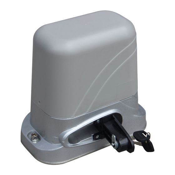
TANKER C600
STW-000026
STI-000026
EN
FR
DE
!
ES
PT
IT
NL
PL
Werbung
Inhaltsverzeichnis
Fehlerbehebung

Verwandte Anleitungen für Casanoov TANKER C600


Inhaltszusammenfassung für Casanoov TANKER C600
- Seite 1 TANKER C600 STW-000026 STI-000026 CAUTION / ATTENTION / ACHTUNG / ATENCIÓN / ATTENZIONE / AANDACHT / UWAGA The manual should be read prior to beginning installation and keep after Le manuel doit être lu avant de commencer l’installation et conservé après Das Handbuch sollte vor Beginn der Installation gelesen und nach der Installation aufbewahrt werden.
- Seite 2 Manual translated from English version using automatic translator. In case of question please refer to english version.
- Seite 3 CAUTION • This product must be installed by well-trained skilled personnel in compliance with the safety regulations the field of residential and commercial swing gate opener devices. Unqualified personnel may damage the instruments and cause harm to the public. • Electric Power must be disconnected prior to installation, or performing any maintenance. •...
-
Seite 4: Tools Required
Tools Required (Required) (Required) (Required) (Required) (Required) (Required) (Required) (Recommended) - Seite 5 Serial Number...
-
Seite 6: Product Overview
Product overview Technical specifications Max gate weight : 600 KG Motor voltage : 230V - 370W Input power : 220VAC±10%/110VAC±10% Environment Temperature : -25°C ~ +55°C Frequency : 50Hz/60Hz Protection Class : IP55 Output gear module : M=4 Open(close) speed : v=12m/min Output gear number: Z=16 Maximum pull : 1100N Output torque:30.0 N.m... - Seite 7 Swing Gate automation Features & Options ALARM LAMP PHOTOCELL PUSH BUTTON GATE MOTOR GEAR RACK TRANSMITTER Manual unlocking Insert key, rotate 90° clockwise. Releas arm in torsion. Wriggle 90°. Gate ‘s motor will be in released.
- Seite 8 General options and accessories 1. Stylish appearance design and built-in control panel integrated inside the mechanism, no external controller or receiver needed. 2. Built in limit switch allowing the motor to switch off once the cycle is finished. 3. Built in manual override with 2 supplied unique override keys in case of emergency or power failure. 4.
- Seite 9 Rack Fixing Set the gear-motor on manual unlocking. Wide open the gate’s door. Place the rack: place the first element on the pinion and fix it with screws to the gate. Move the door manually and repeat the procedure with the other elements using adistance spacer to ensure the correct position from the rack.
- Seite 10 Control board setting Yellow Blue...
- Seite 11 Installation of the motor on the control board Please note Factory setting is install motor on the right of gate! OPENING TO THE RIGHT...
- Seite 12 OPENING TO THE LEFT Limit switch option J1 Please note When you exchange red and yellow wire, please check if the motor can close and stop normally. If can’t , please up or down the “J1” to the opposite direction. Note: “J1”...
- Seite 13 Connection of the flashing light Connection of infra-red photocells...
-
Seite 14: Function Testing
Function testing Terminal stop detection Limit switch option J1 Power switch Programming set- ting Learning button Close sensitivity adjusting Open sensitivity adjusting Connect to start capacitor... - Seite 15 7.1 / 7.2 Gate open and close - blocked detection Close sentivity adjusting Open sentivity adjusting A. High sensitivity : when the motor is rotation, will meet some minor resistance, then control board will send a signal to let motor stop rotating. B.
- Seite 16 5&6: Auto-close setting time when pedestrian mode is activated. When remote control triggers the pedestrian mode (remote control button 2 or 4), the gate will stop after opening for 6s. If auto-close function activated, the gate will auto-close after gate open to 6s. Auto-close time setting as follows: •...
- Seite 17 7.5 Motor-Start Capacitors: Capacitors are connected with control board. Before using the Connect to start motor, please confirmed the capacitor interface of capacitors is secure. 7.6 Limited switch options (J1): Limit switch is used to switch terminal stop detection interface, that direction of open and close Limit switch the gate.
-
Seite 18: Troubleshooting
Trouble Shooting Problem Possible causes Repair method Gate fails to operate. 1. Check the clutch states, power-driven state or not? > Recovery 2. Power no indication, and power trip. > To restore power. 3. The fuse has broken > Change the fuse. 4. - Seite 19 FUNCTION DIP SWITCH MODE Limit mode Dip 1/OFF NC mode(Factory setting) setting Dip 1/ON No Mode Limit switch direction Normal : Short circuit cap simultaneously No1 and No2 of J1 (Factory setting) If motor system install at left of gate . Please adjust the J1 ,short the cap simultaneously No2 and No3 setting (J1) Infrared Dip 2/OFF...
- Seite 20 FLASH LAMP WARNING Safety Instruction 1. For security, please read the user manual carefully before initial operation; 2. Please be sure the power is off before connecting, the product is produced without fuse; Flash lamp specifications Working voltage 12-265 VAC/DC <...
-
Seite 21: Declaration Of Ce Conformity
Declaration of CE conformity Technical report number : DL-2020061822E/ DL-2020061793S Hoortrade SAS 4 bis avenue jean françois raclet 69007 lyon France Declares that the following product/ SKU : JJ-PYM-A2201 – HOORTRADE reference : STI-000026 Satisfies the essential requisites established in following directives : Low Voltage Directive EN 60335-1 :2012+A11 :2014+A13 :2017+A1 :2019+A14 :2019 And satisfies the following standards :... - Seite 22 ATTENTION • Ce produit doit être installé par un personnel qualifié et bien formé, en conformité avec les règles de sécurité en vigueur dans le domaine des dispositifs d’ouverture de portails à battants résidentiels et commerciaux. Un personnel non qualifié peut endommager les instruments et causer des dommages au public.
- Seite 23 OUTILS NECESSAIRES (Obligatoire) (Obligatoire) (Obligatoire) (Obligatoire) (Obligatoire) (Obligatoire) (Obligatoire) (Recommandé)
-
Seite 24: Numéro De Série
Numéro de série... -
Seite 25: Vue Générale
Vue Générale Données techniques Tension du moteur : 230V - 370W Poids max du portail : 600 KG Puissance d’entrée : 220VAC±10%/110VAC±10% Température de l’environnement : -25°C ~ +55°C Fréquence : 50Hz/60Hz Classe de protection : IP55 Module d’engrenage de sortie : M=4 Vitesse d’ouverture (fermeture) : v=12m/min Nombre d’engrenages de sortie : Z=16 Effort maximal : 1100N... - Seite 26 Automatisation du portail pivotant Caractéristiques et options LAMPE D’ALARME PHOTO-CELLULE BOUTON-POUSSOIR MOTEUR DE PORTAIL RACK D’ENGRENAGES EMETTEUR Ouverture manuelle Insérer la clé, tourner de 90° dans le sens des aiguilles d’une montre. Relâcher le bras en torsion. Tourner de 90°. Le moteur de la porte sera libéré.
- Seite 27 Options générales et accessoires 1. Design d’apparence élégante et panneau de contrôle intégré dans le mécanisme, aucun contrôleur ou récepteur externe n’est nécessaire. 2. Interrupteur de fin de course intégré permettant au moteur de s’éteindre une fois le cycle terminé. 3.
- Seite 28 Fixation des racks Régler le moteur à engrenages sur le déverrouillage manuel. Ouvrez grand la porte du portail. Placez la crémaillère : placez le premier élément sur le pignon et fixez-le avec des vis sur le portail. Déplacez la porte manuellement et répétez la procédure avec les autres éléments en utilisant l’entre- toise d’adistance pour assurer la bonne position de la crémaillère.
- Seite 29 Paramétrage de la carte de contrôle Rouge Jaune Bleu...
- Seite 30 Installation du moteur sur le tableau de commande Veuillez noter : Le réglage d’usine est d’installer le moteur à droite du portail ! OUVERTURE À DROITE...
- Seite 31 OUVERTURE À GAUCHE Bleu Rouge L’interrupteur de fin de course (J1) Jaune Veuillez noter Lorsque vous échangez les fils rouge et jaune, veuillez vérifier si le moteur peut se fermer et s’arrêter normalement. Si ce n’est pas le cas, veuillez monter ou descendre le «J1» dans la direction opposée. Note : «J1»...
- Seite 32 Connexion des lampes flash Connexion des cellules photoélectriques...
-
Seite 33: Test De Fonctionnement
Test de fonctionnement Interface de détection d’arrêt de terminal L’interrupteur de fin de course (J1) Interrupteur d’ali- mentation Paramètres de programmation Bouton d’apprentissage Ajustement de la sensibilité de fermeture Ajustement de la sensibilité d’ouverture Connexion au condensateur de démarrage du moteur... - Seite 34 7.1 / 7.2 Ouverture et fermeture du portail - détection bloquée Ajustement de la sensibilité de fermeture Ajustement de la sensibilité d’ouverture A. Haute sensibilité : lorsque le moteur tourne, il rencontre une légère résistance, puis la carte de contrôle envoie un signal pour que le moteur s’arrête de tourner.
- Seite 35 5&6 : Temps de réglage de la fermeture automatique lorsque le mode piéton est activé. Lorsque la télécommande déclenche le mode piéton (bouton 2 ou 4 de la télécommande), le portail s’arrête après 6s d’ouverture. Si la fonction de fermeture automatique est activée, le portail se fermera automatiquement après 6s d’ouverture.
- Seite 36 7.5 Condensateurs de démarrage du moteur : Les condensateurs sont reliés à Condensateurs de un tableau de commande. Avant démarrage du moteur d’utiliser le moteur, veuillez confirmer que l’interface des condensateurs est sécurisée. 7.6 L’interrupteur de fin de course (J1) : L’interrupteur de fin de course est L’interrupteur de utilisé...
-
Seite 37: Dépannage
Dépannage Problème Causes possibles Méthode de réparation La porte ne fonctionne pas. 1. Vérifier les états de l’embrayage, qu’il soit motorisé > Recouvrement ou non ? 2. Pas d’indication de puissance, et déclenchement de > Rétablir l’alimentation. la puissance. 3. Le fusible est cassé. >... - Seite 38 FONCTION INTERRUPTEUR À BASCULE MODE Réglage du Dip 1/OFF Mode NC (réglage d’usine) mode limite Dip 1/ON Pas de mode Réglage du sens de rotation Normal : court-circuit capuchon simultanément n°1 et n°2 de J1 (Réglage d’usine) Si le système de moteur est installé à gauche du portail . des interrupteurs de fin de Veuillez ajuster le J1 ,court-circuiter le bouchon simultanément No2 et No3 course (J1)
- Seite 39 LAMPE FLASH AVERTISSEMENT Instruction de sécurité 1. Pour des raisons de sécurité, veuillez lire attentivement le manuel d’utilisation avant la première utilisation ; 2. Veuillez vous assurer que l’alimentation électrique est coupée avant de brancher le produit, celui-ci étant fabriqué sans fusible ; Spécifications des lampes flash Tension de fonctionnement 12-265 VAC/DC...
-
Seite 40: Déclaration De Conformité Ce
Déclaration de conformité CE Numéro du rapport technique : DL-2020061822E/ DL-2020061793S Hoortrade SAS 4 bis avenue jean françois raclet 69007 lyon France Déclare que le produit suivant SKU : JJ-PYM-A2201 – HOORTRADE référence : STI-000026 Satisfait aux exigences essentielles établies dans les directives suivantes : Low Voltage Directive EN 60335-1 :2012+A11 :2014+A13 :2017+A1 :2019+A14 :2019 Et satisfait aux normes suivantes :... - Seite 41 VORSICHT: • Dieses Produkt muss von gut ausgebildetem Fachpersonal unter Einhaltung der Sicherheitsvorschriften im Bereich der Drehtorantriebe für den privaten und gewerblichen Bereich installiert werden. Unqualifiziertes Personal kann die Geräte beschädigen und der Öffentlichkeit Schaden zufügen. • Vor der Installation oder der Durchführung von Wartungsarbeiten muss die Stromversorgung unterbrochen werden.
-
Seite 42: Erforderliche Werkzeuge
Erforderliche Werkzeuge (Erforderlich) (Erforderlich) (Erforderlich) (Erforderlich) (Erforderlich) (Erforderlich) (Erforderlich) (Empfohlen) - Seite 43 Seriennummer...
-
Seite 44: Technische Spezifikationen
Produktübersicht Technische Spezifikationen Motorspannung : 230V - 370W Maximales Gewicht einer einzelnen Entlüftung : 600 KG Eingangsleistung : 220VAC±10%/110VAC±10% Umgebungstemperatur : -25°C ~ +55°C Abtriebszahnrad-Modul : 50Hz/60Hz Schutzklasse : IP55 Abtriebsrad-Nummer : M=4 Geschwindigkeit Öffnen (Schließen) : v=12m/min Abtriebsdrehmoment : Z=16 Maximale Zugkraft : 1100N Output torque:30.0 N.m Luftfeuchtigkeit bei der Arbeit : ≤85%... - Seite 45 Swing Gate-Automatisierung Merkmale und Optionen ALARMLAMPE FOTOZELLE DRUCKTASTE TOR-MOTOR ZAHNSTANGE SENDER Manuelle Entriegelung Schlüssel einsetzen, um 90° im Uhrzeigersinn drehen. Arm in Torsion loslassen. 90° wackeln. Der Motor des Tores wird freigegeben.
-
Seite 46: Allgemeine Optionen Und Zubehör
Allgemeine Optionen und Zubehör 1. Stilvolles Erscheinungsbild und im Mechanismus integriertes Bedienfeld, kein externer Controller oder Empfänger erforderlich. 2. Eingebauter Endschalter, mit dem der Motor nach Beendigung des Zyklus abgeschaltet werden kann. 3. Eingebaute Handnotbetätigung mit 2 mitgelieferten eindeutigen Tasten für den Fall eines Notfalls oder Stromausfalls. -
Seite 47: Einbau Des Begrenzungsmagneten
Gestellbefestigung. Stellen Sie den Getriebemotor auf manuelle Entriegelung. Öffnen Sie die Tür des Tores weit. Setzen Sie die Zahnstange ein: Setzen Sie das erste Element auf das Ritzel und befestigen Sie es mit Schrauben am Tor. Bewegen Sie das Tor von Hand und wiederholen Sie den Vorgang mit den anderen Elementen unter Verwendung eines Distanzstücks, um die korrekte Position von der Zahnstange zu gewährleisten. - Seite 48 Einrichten der Regelkarte Gelb Blau...
- Seite 49 Installation of the motor on the control board Bitte beachten Sie Werkseitig ist der Motor rechts vom Tor eingebaut! ÖFFNUNG NACH RECHTS...
- Seite 50 LINKE ÖFFNUNG Blau Der Endschalter (J1) Gelb Bitte beachten Sie Beim Vertauschen des roten und gelben Kabels prüfen Sie bitte, ob der Motor normal schließen und stoppen kann. Falls nicht, bewegen Sie bitte «J1» in der entgegengesetzten Richtung nach oben oder unten.
- Seite 51 Anschluss für Blitzlampe Photoelektrische Zellenverbindung...
- Seite 52 Funktionsprüfung Schnittstelle zur Erkennung von Endanschlägen Der Endschalter (J1) Netzschalter Programmier-Pa- rameter Teach-Taste Einstellung der Schließempfindlich- keit Einstellung der Öff- nungsempfindlichkeit Anschluss an Motoranlaufkondensator...
- Seite 53 7.1 / 7.2 Öffnen und Schließen des Tors - Erkennung blockiert Einstellung der Schließempfindlichkeit Einstellung der Öffnungsempfindlichkeit A. Hohe Empfindlichkeit: Wenn der Motor läuft, stößt er auf einen leichten Widerstand, dann sendet die Steuerplatine ein Signal zum Stoppen des Motors. B.
-
Seite 54: Erlernen Der Fernbedienungscodes
5&6: Einstellzeit für die automatische Schließung bei Aktivierung des Fußgängermodus. Wenn die Fernsteuerung den Fußgängermodus auslöst (Taste 2 oder 4 auf der Fernsteuerung), stoppt das Tor nach 6 s Öffnung. Wenn die automatische Schliessfunktion aktiviert ist, schliesst das Tor nach 6 s automatisch. Die automatische Schließzeit wird wie folgt eingestellt: - Nr. - Seite 55 7.5 Motorstart-Kondensatoren : Die Kondensatoren sind an ein Bedienfeld angeschlossen. Motor- Bevor Sie den Motor in Betrieb Startkondensatoren nehmen, vergewissern Sie sich bitte, dass die Kondensatorschnittstelle sicher ist. 7.6 Der Endschalter (J1) : Der Endschalter dient Der Endschalter zum Umschalten der (J1) Stopperkennungsschnittstelle des Terminals, d.h.
-
Seite 56: Fehlerbehebung
Fehlerbehebung Problem Mögliche Ursachen Methode der Reparatur Die Tür funktioniert nicht. 1. Überprüfen Sie den Zustand der Kupplung, ob sie > Sammlung motorisiert ist oder nicht? 2. Keine Leistungsanzeige und Freigabe der Leistung. > Energie wiederherstellen. 3. Die Sicherung ist defekt. >... - Seite 57 FUNKTION KIPPSCHALTER MODUS Einstellen des Dip 1/OFF NC-Modus (Werkseinstellung) Grenzwertmo- Dip 1/ON Kein Modus Normal : Kurzschluss der Kappe gleichzeitig Nr. 1 und Nr. 2 von J1 (Werkseinstellung) Einstellung der Drehrich- Wenn das Motorsystem auf der linken Seite des Tores installiert ist . tung der Endschalter (J1) Bitte stellen Sie J1 ein, kurzschließen Sie den Stecker gleichzeitig No2 und No3.
-
Seite 58: Spezifikationen Für Blitzlampen
BLITZLAMPE WARNUNG Sicherheitsanweisung 1. Bitte lesen Sie zur Sicherheit vor der Inbetriebnahme das Benutzerhandbuch sorg- fältig durch; 2. Bitte vergewissern Sie sich vor dem Anschließen, dass der Strom abgeschaltet ist; das Produkt ist ohne Sicherung hergestellt; Spezifikationen für Blitzlampen Arbeitsspannung 12-265 VAC/DC <... -
Seite 59: Eg-Konformitätserklärung
EG-Konformitätserklärung Nummer des technischen Berichts : DL-2020061822E/ DL-2020061793S Hoortrade SAS 4 bis avenue jean françois raclet 69007 lyon France Erklärt, dass das folgende Produkt/ SKU : JJ-PYM-A2201 – HOORTRADE Referenz : STI-000026 Erfüllt die wesentlichen Anforderungen, die in folgenden Richtlinien festgelegt sind Low Voltage Directive EN 60335-1 :2012+A11 :2014+A13 :2017+A1 :2019+A14 :2019 Und erfüllt die folgenden Normen:... - Seite 60 PRECAUCIÓN: • Este producto debe ser instalado por personal calificado y bien entrenado en cumplimiento de las normas de seguridad en el campo de los dispositivos abridores de puertas batientes residenciales y comerciales. El personal no cualificado puede dañar los instrumentos y causar daños al público.
-
Seite 61: Herramientas Necesarias
Herramientas necesarias (Requerido) (Requerido) (Requerido) (Requerido) (Requerido) (Requerido) (Requerido) (Recomendado) -
Seite 62: Número De Serie
Número de serie... -
Seite 63: Resumen Del Producto
Resumen del producto Especificaciones técnicas El voltaje del motor : 230V - 370W Peso máximo de la puerta : 600 KG Potencia de entrada : 220VAC±10%/110VAC±10% La temperatura ambiental : -25°C ~ +55°C Frecuencia : 50Hz/60Hz Clase de protección : IP55 Módulo de engranaje de salida : M=4 Velocidad de apertura (cierre) : v=12m/min Número de engranajes de salida : Z=16... - Seite 64 Automatización de puertas batientes Características y opciones LÁMPARA DE ALARMA FOTOCÉLULA PULSAR EL BOTÓN MOTOR DE LA PORTAEQUIPAJES PUERTA TRANSMISOR Desbloqueo manual Inserte la llave, gire 90° en el sentido de las agujas del reloj. Libere el brazo en torsión. Gira 90°. El motor de la puerta se liberará.
-
Seite 65: Montaje Del Motor
Opciones y accesorios generales 1. Diseño de apariencia elegante y panel de control integrado en el interior del mecanismo, no se necesita ningún controlador o receptor externo. 2. Interruptor de fin de carrera incorporado que permite al motor apagarse una vez terminado el ciclo. 3. - Seite 66 Arreglar el estante Ponga el motorreductor en desbloqueo manual. Abrir la puerta de par en par. Colocar la cremallera: colocar el primer elemento en el piñón y fijarlo con tornillos a la puerta. Mueva la puerta manualmente y repita el procedimiento con los demás elementos utilizando el espaciador de distancia para asegurar la posición correcta de la cremallera.
- Seite 67 Configurando la carta de control Rojo Amarillo Azul...
- Seite 68 Installation of the motor on the control board Por favor, tenga en cuenta El ajuste de fábrica es instalar el motor a la derecha de la puerta. ABERTURA A LA DERECHA...
- Seite 69 APERTURA DE LA IZQUIERDA Azul Rojo El interruptor de límite (J1) Amarillo Por favor, tenga en cuenta Al cambiar los cables rojo y amarillo, por favor, compruebe si el motor puede cerrarse y detenerse normalmente. Si no, por favor mueva «J1» arriba o abajo en la dirección opuesta. Nota: «J1»...
- Seite 70 Conexión de la lámpara de flash Conexión de la célula fotoeléctrica...
-
Seite 71: Prueba De Funcionamiento
Prueba de funcionamiento Interfaz de detección de parada de terminal El interruptor de límite (J1) Interruptor de encendido Parámetros de programación El botón de aprendizaje Ajuste de la sensibilidad de cierre Ajuste de la sensibilidad de apertura Conexión al condensador de arranque del motor... - Seite 72 7.1 / 7.2 Apertura y cierre de la puerta - detección bloqueada Ajuste de la sensibilidad de cierre Ajuste de la sensibilidad de apertura A. Alta sensibilidad: cuando el motor está en marcha, encuentra una ligera resistencia, entonces el ta- blero de control envía una señal para detener el motor.
- Seite 73 5&6: Establecer el tiempo de cierre automático cuando se activa el modo peatonal. Cuando el mando a distancia activa el modo peatonal (botón 2 o 4 del mando a distancia), la puerta se detiene después de 6s de apertura. Si se activa la función de cierre automático, la puerta se cerrará automáticamente después de 6s de apertura.
- Seite 74 7.5 Condensadores de arranque del motor : Los condensadores están Condensadores de conectados a un panel de arranque del motor control. Antes de operar el motor, por favor confirme que la interfaz del condensador es segura. 7.6 El interruptor de fin de carrera (J1) : El interruptor de El interruptor de fin de carrera se...
-
Seite 75: Solución De Problemas
Solución de problemas Problema Posibles causas Método de reparación La puerta no funciona. 1. ¿Comprobar el estado del embrague, si está motori- > Colección zado o no? 2. No hay indicación de energía, y se libera la energía. > Restaurar la energía. 3. - Seite 76 FUNCIÓN INTERRUPTOR DE CONMUTACIÓN MODO Ajustar el Dip 1/OFF Modo NC (ajuste de fábrica) modo de Dip 1/ON No hay modo límite Ajustar la dirección de rota- Normal : cortocircuito de la tapa simultáneamente n°1 y n°2 de J1 (ajuste de fábrica) Si el sistema de motor está...
- Seite 77 LÁMPARA DE FLASH ADVERTENCIA Instrucciones de seguridad 1. Por seguridad, por favor lea el manual de usuario cuidadosamente antes de la operación inicial; 2. Por favor, asegúrese de que la alimentación esté apagada antes de conectarla, el producto se produce sin fusible; Especificaciones de la lámpara de flash Voltaje de trabajo 12-265 VAC/DC...
- Seite 78 Declaración de conformidad CE Número de informe técnico : DL-2020061822E/ DL-2020061793S Hoortrade SAS 4 bis avenue jean françois raclet 69007 lyon France Declara que el siguiente producto/ SKU : JJ-PYM-A2201 – HOORTRADE référence : STI-000026 Cumple los requisitos esenciales establecidos en las siguientes directrices : Niederspannungsrichtlinie EN 60335-1 :2012+A11 :2014+A13 :2017+A1 :2019+A14 :2019 Y satisface los siguientes estándares :...
- Seite 79 CUIDADO • Este produto deve ser instalado por pessoal qualificado e bem treinado, em conformidade com as normas de segurança no domínio dos dispositivos de abertura de portões basculantes residenciais e comerciais. O pessoal não qualificado pode danificar os instrumentos e causar danos ao público.
- Seite 80 Ferramentas Necessárias (Obrigatório) (Obrigatório) (Obrigatório) (Obrigatório) (Obrigatório) (Obrigatório) (Obrigatório) (Recomendado)
-
Seite 81: Número De Série
Número de série... -
Seite 82: Resumo Do Produto
Resumo do produto Especificações técnicas Tensão do motor : 230V - 370W Peso máximo da porta : 600 KG Potência de entrada : 220VAC±10%/110VAC±10% Temperatura ambiente : -25°C ~ +55°C Frequência : 50Hz/60Hz Classe de protecção : IP55 Módulo de saída de engrenagens : M=4 Velocidade de abertura (fecho) : v=12m/min Número de velocidades de saída : Z=16 Esforço máximo : 1100N... - Seite 83 Características e opções de automação do Swing Gate LÂMPADA DE ALARME FOTOCÉLULA BOTÃO DE PRESSÃO MOTOR DA PORTA SUPORTE DE ENGRENAGEM EMISSORA Desbloqueio manual Inserir chave, rodar 90° no sentido dos ponteiros do relógio. Soltar braço em torção. Regatear 90°. O motor do portão será...
- Seite 84 Opções gerais e acessórios 1. Design elegante e painel de controlo integrado no interior do mecanismo, não é necessário um controlador ou receptor externo. 2. Interruptor de fim de curso incorporado que permite ao motor desligar-se uma vez terminado o ciclo. 3.
- Seite 85 Fixação de cremalheira Colocar o moto-redutor em desbloqueio manual. Abrir bem a porta do portão. Colocar a cremalheira: colocar o primeiro elemento sobre o pinhão e fixá-lo com parafusos à porta. Deslocar a porta manualmente e repetir o procedimento com os outros elementos utilizando espaçador de distância para garantir a posição correcta a partir da cremalheira.
- Seite 86 Elaboração do gráfico de controlo Vermelho Amarelo Azul...
- Seite 87 Installation of the motor on the control board Por favor note que A configuração de fábrica é instalar o motor à direita do portão! ABERTURA À DIREITA...
- Seite 88 ABERTURA À ESQUERDA Azul Vermelho O interruptor final (J1) Amarelo Por favor note que Ao trocar os fios vermelho e amarelo, verifique se o motor pode fechar e parar normalmente. Caso contrário, por favor mova «J1» para cima ou para baixo na direcção oposta. Nota: «J1»...
- Seite 89 Ligação da lâmpada flash Ligação de célula fotoeléctrica...
- Seite 90 Testes de funcionamento Interface de detecção de paragem de terminais O interruptor final (J1) Interruptor de alimentação Parâmetros de pro- gramação Botão Teach Ajuste da sensibilidade de fecho Ajuste da sensibilidade da abertura Ligação ao conden- sador de arranque do motor...
- Seite 91 7.1 / 7.2 Abertura e fecho da porta - detecção bloqueada Ajuste da sensibilidade de fecho Ajuste da sensibilidade da abertura A. Alta sensibilidade: quando o motor está em funcionamento, encontra uma ligeira resistência, então a placa de comando envia um sinal para parar o motor. B.
- Seite 92 5&6: Tempo de fecho automático quando o modo pedestre é activado. Quando o telecomando activa o modo pedestre (botão 2 ou 4 do telecomando), a porta pára após 6s de abertura. Se a função de fecho automático for activada, a porta fecha-se automaticamente após 6s de abertura. A hora de fecho automático é...
- Seite 93 7.5 Condensadores de arranque do motor : Os condensadores são ligados Condensadores de a um painel de controlo. Antes arranque de motores de operar o motor, confirme se a interface do condensador está segura. 7.6 O interruptor final (J1) : O interruptor final é...
-
Seite 94: Resolução De Problemas
Resolução de Problemas Problema Causas Possíveis Método de reparação A porta não funciona. 1. Verificar o estado da embraiagem, quer seja motori- > Recolha zada ou não? 2. Sem indicação de energia, e libertação de energia. > Restaurar potência. 3. O rastilho está partido. >... - Seite 95 FUNÇÃO INTERRUPTOR BASCULANTE MODO Definição do Dip 1/OFF Modo NC (configuração de fábrica) modo limite Dip 1/ON Sem modo Ajuste do sentido de rota- Normal : curto-circuito da tampa simultaneamente n°1 e n°2 de J1 (configuração de fábrica) Se o sistema motor estiver instalado do lado esquerdo do portão . ção dos interruptores de Por favor, ajuste J1, curto-circuite a ficha simultaneamente n.º...
- Seite 96 LÂMPADA FLASH AVISO Instrução de segurança 1. Para segurança, leia atentamente o manual do utilizador antes da operação inicial; 2. Por favor, certifique-se de que a energia está desligada antes de ligar, o produto é produzido sem fusível; Especificações da lâmpada flash Tensão de funcionamento 12-265 VAC/DC <...
- Seite 97 Declaração de conformidade CE Número do relatório técnico : DL-2020061822E/ DL-2020061793S Hoortrade SAS 4 bis avenue jean françois raclet 69007 lyon France Declara que o seguinte produto/ SKU : JJ-PYM-A2201 – HOORTRADE Referência : STI-000026 Satisfaz os requisitos essenciais estabelecidos nas seguintes directivas : Low Voltage Directive EN 60335-1 :2012+A11 :2014+A13 :2017+A1 :2019+A14 :2019 E satisfaz as seguintes normas:...
- Seite 98 ATTENZIONE • Questo prodotto deve essere installato da personale qualificato e ben addestrato in conformità con le norme di sicurezza nel campo dei dispositivi di apertura dei cancelli a battente residenziali e commerciali. Personale non qualificato può danneggiare gli strumenti e causare danni al pubblico.
-
Seite 99: Strumenti Richiesti
Strumenti richiesti (Obbligatorio) (Obbligatorio) (Obbligatorio) (Obbligatorio) (Obbligatorio) (Obbligatorio) (Obbligatorio) (Raccomandato) - Seite 100 Numéro de série...
-
Seite 101: Panoramica Dei Prodotti
Panoramica dei prodotti Specifiche tecniche Tensione del motore : 230V - 370W Peso massimo del cancello : 600 KG Potenza in ingresso : 220VAC±10%/110VAC±10% Temperatura ambientale : -25°C ~ +55°C Frequenza : 50Hz/60Hz Classe di protezione : IP55 Modulo riduttore di uscita : M=4 Velocità... - Seite 102 Automazione Swing Gate Caratteristiche e opzioni LAMPADA DI ALLARME FOTOCELLULA PREMERE IL PULSANTE MOTORE DEL CREMAGLIERA CANCELLO TRASMETTITORE Sbloccaggio manuale Inserire la chiave, ruotare di 90° in senso orario. Rilasciare il braccio in torsione. Spostare di 90°. Il motore del cancello verrà rilasciato.
-
Seite 103: Montaggio Del Motore
Opzioni generali e accessori 1. 2. Design elegante e pannello di controllo integrato all’interno del meccanismo, non è necessario un controllore o ricevitore esterno. 2. 2. Interruttore di fine corsa integrato che permette al motore di spegnersi una volta terminato il ciclo. 3. - Seite 104 Fissaggio del rack Impostare il motoriduttore sullo sbloccaggio manuale. Spalancare la porta del cancello. Posizionare la cremagliera: posizionare il primo elemento sul pignone e fissarlo con viti al cancello. Spostare la porta manualmente e ripetere la procedura con gli altri elementi utilizzando un distanziale per garantire la corretta posizione dalla cremagliera.
- Seite 105 Impostazione della tabella di controllo Rosso Giallo...
- Seite 106 Installation of the motor on the control board Si prega di notare L’impostazione di fabbrica è installare il motore a destra del cancello! APERTURA A DESTRA...
- Seite 107 APERTURA A SINISTRA Rosso Il finecorsa (J1) Giallo Si prega di notare Quando si scambiano i fili rosso e giallo, controllare se il motore può chiudersi e fermarsi normalmente. In caso contrario, spostare «J1» verso l’alto o verso il basso nella direzione opposta. Nota: «J1»...
- Seite 108 Collegamento lampada flash Collegamento della cellula fotoelettrica...
-
Seite 109: Test Di Funzionamento
Test di funzionamento Interfaccia di rilevamento dell’ar- resto terminale Il finecorsa (J1) Interruttore di alimentazione Parametri di programmazione Pulsante di apprendimento Regolazione della sensibilità di chiusura Regolazione della sensibilità di apertura Collegamento al condensatore di avviamento del motore... - Seite 110 7.1 / 7.2 Apertura e chiusura del cancello - rilevamento bloccato Regolazione della sensibilità di chiusura Regolazione della sen- sibilità di apertura A. Elevata sensibilità: quando il motore è in funzione, incontra una leggera resistenza, poi la scheda di controllo invia un segnale di arresto del motore. B.
- Seite 111 5&6: Impostazione del tempo per la chiusura automatica quando viene attivata la modalità pedonale. Quando il telecomando attiva la modalità pedonale (tasto 2 o 4 sul telecomando), il cancello si ferma dopo 6s di apertura. Se la funzione di chiusura automatica è attivata, il cancello si chiude automaticamente dopo 6s di apertura.
- Seite 112 7.5 Condensatori di avviamento motore : I condensatori sono collegati ad Condensatori di un pannello di controllo. Prima avviamento del motore di mettere in funzione il motore, verificare che l’interfaccia del condensatore sia sicura. 7.6 Il finecorsa (J1) : Il finecorsa serve a commutare l’interfaccia di rilevamento Il finecorsa (J1) dell’arresto del terminale, cioè...
-
Seite 113: Risoluzione Dei Problemi
Risoluzione dei problemi Problema Cause possibili Metodo di riparazione La porta non funziona. 1. Controllare lo stato della frizione, sia essa motoriz- > Raccolta zata o meno? 2. Nessuna indicazione di potenza, e il rilascio di po- > Ripristinare la potenza. tenza. - Seite 114 FUNZIONE INTERRUTTORE A LEVETTA MODALITÀ Imposta- Dip 1/OFF Modo NC (impostazione di fabbrica) zione del Dip 1/ON Nessun modo modo limite Regolazione del senso di Normale : corto circuito del tappo contemporaneamente n°1 e n°2 di J1 (impostazione di fabbrica) Se il sistema a motore è...
- Seite 115 LAMPADA FLASH ATTENZIONE Istruzioni di sicurezza 1. Per motivi di sicurezza, leggere attentamente il manuale d’uso prima della messa in funzione; 2. Assicurarsi che l’alimentazione sia spenta prima del collegamento, il prodotto è prodotto senza fusibile; Specifiche della lampada flash Tensione di lavoro 12-265 VAC/DC <...
-
Seite 116: Dichiarazione Di Conformità Ce
Dichiarazione di conformità CE Numero del rapporto tecnico : DL-2020061822E/ DL-2020061793S Hoortrade SAS 4 bis avenue jean françois raclet 69007 lyon France Dichiara che il seguente prodotto/ SKU : JJ-PYM-A2201– HOORTRADE Riferimento : STI-000026 Soddisfa i requisiti essenziali stabiliti nelle seguenti direttive : Low Voltage Directive EN 60335-1 :2012+A11 :2014+A13 :2017+A1 :2019+A14 :2019 E soddisfa i seguenti standard :... - Seite 117 LET OP • Dit product moet worden geïnstalleerd door goed opgeleid en vakkundig personeel met inachtneming van de veiligheidsvoorschriften op het gebied van huishoudelijke en commerciële draaipoortopeners. Ongekwalificeerd personeel kan de instrumenten beschadigen en het publiek schade toebrengen. • Voorafgaand aan de installatie of het uitvoeren van onderhoud moet de elektrische stroom worden uitgeschakeld.
- Seite 118 Vereist gereedschap (Verplicht) (Verplicht) (Verplicht) (Verplicht) (Verplicht) (Verplicht) (Verplicht) (Aanbevolen)
- Seite 119 Serienummer...
-
Seite 120: Technische Specificaties
Productoverzicht Technische specificaties Motorspanning : 230V - 370W Max. gewicht van een enkele ontluchter : 600 KG Ingangsvermogen : 220VAC±10%/110VAC±10% Milieutemperatuur : -25°C ~ +55°C Frequentie : 50Hz/60Hz Beschermingsklasse : IP55 Uitgaande tandwielkastmodule : M=4 Open (sluit) snelheid : v=12m/min Uitgangsversnelling nummer : Z=16 Maximale trekkracht : 1100N Uitgangskoppel : 30.0 N.m... - Seite 121 Swing Gate automatisering Eigenschappen & Opties ALARMLAMP FOTOCEL DRUKKNOP POORTMOTOR VERSNELLINGSBAK ZENDER Handmatige ontgrendeling Steek de sleutel erin, draai hem 90° met de klok mee. Laat de arm los in torsie. Wrikken 90°. De motor van de poort wordt losgelaten.
- Seite 122 Algemene opties en accessoires 1. Stijlvol uitzichtdesign en ingebouwd bedieningspaneel geïntegreerd in het mechanisme, geen externe controller of ontvanger nodig. 2. Ingebouwde eindschakelaar waarmee de motor kan worden uitgeschakeld zodra de cyclus is voltooid. 3. Ingebouwde handbediening met 2 bijgeleverde unieke overbruggingssleutels in geval van nood of stroomuitval. 4.
- Seite 123 Rack Fixing. Zet de motorreductor op manuele ontgrendeling. Breed de deur van het hek open. Plaats het rek: plaats het eerste element op het rondsel en bevestig het met schroeven aan de poort. Verplaats de deur met de hand en herhaal de procedure met de andere elementen met behulp van een afstandhouder om de juiste positie ten opzichte van het rek te garanderen.
- Seite 124 Opzetten van de regelkaart Rood Geel Blauw...
- Seite 125 Installation of the motor on the control board LET OP Fabrieksinstelling is installatiemotor rechts van de poort! OPENING NAAR RECHTS...
- Seite 126 LINKER OPENING Blauw Rood De eindschakelaar (J1) Geel Let op Controleer bij het verwisselen van de rode en gele draden of de motor normaal kan sluiten en stoppen. Zo niet, ga dan met «J1» omhoog of omlaag in de tegenovergestelde richting. Opmerking: «J1»...
- Seite 127 Aansluiting voor flitslampen Foto-elektrische celverbinding...
- Seite 128 Functiecontrole Terminal stop detectie-interface De eindschakelaar (J1) Stroomschakelaar Programmeer- parameters Leerknop Aanpassing sluitings- gevoeligheid Aanpassing van de openingsgevoeligheid Aansluiting op de motorstartcondensator...
- Seite 129 7.1 / 7.2 Openen en sluiten van de poort - detectie geblokkeerd Aanpassing slui- tingsgevoeligheid Aanpassing van de openingsgevoeligheid A. Hoge gevoeligheid: als de motor draait, stuit hij op een lichte weerstand, dan stuurt de besturings- printplaat een signaal om de motor te stoppen. B.
- Seite 130 5&6: Instellen van de tijd voor automatisch sluiten wanneer de voetgangersmodus is geactiveerd. Wanneer de afstandsbediening de voetgangersmodus activeert (knop 2 of 4 op de afstandsbediening), stopt de poort na 6 seconden openen. Als de automatische sluitfunctie is geactiveerd, sluit de poort automatisch na 6 seconden openen.
- Seite 131 7.5 Motorstartcondensatoren : De condensatoren zijn aangesloten op een Motor bedieningspaneel. Voordat u de startcondensatoren motor in werking stelt, moet u controleren of de interface van de condensator veilig is. 7.6 De eindschakelaar (J1) : De eindschakelaar wordt gebruikt om de stopdetectie- De eindschakelaar interface van de terminal te (J1)
-
Seite 132: Probleemoplossing
Probleemoplossing Probleem Mogelijke oorzaken Methode van herstel De deur werkt niet. 1. De toestand van de koppeling controleren, of deze > Collectie nu gemotoriseerd is of niet? 2. Geen stroomindicatie, en het vrijgeven van de > Herstel de kracht. stroom. 3. - Seite 133 FUNCTIE KNEVELSCHAKELAAR MODUS Instellen van Dip 1/OFF NC-modus (fabrieksinstelling) de grensmo- Dip 1/ON Geen modus Instellen van de draairichting Normaal : kortsluiting van de dop tegelijkertijd n°1 en n°2 van J1 (fabrieksinstelling) Als het motorsysteem aan de linkerkant van de poort is geïnstalleerd. van de eindschakelaars (J1) Stel J1 in, sluit de stekker gelijktijdig af op nr.
- Seite 134 FLITSLAMP WAARSCHUWING Veiligheidsinstructie 1. Lees voor de veiligheid de gebruikershandleiding zorgvuldig door voordat u het apparaat in gebruik neemt; 2. Wees er zeker van dat de stroom is uitgeschakeld voordat u het product aansluit, het product wordt geproduceerd zonder zekering; Specificaties flitslamp Werkspanning 12-265 VAC/DC...
- Seite 135 Verklaring van CE-conformiteit Technisch rapportnummer : DL-2020061822E/ DL-2020061793S Hoortrade SAS 4 bis avenue jean françois raclet 69007 lyon France Verklaart dat het volgende product/ SKU : JJ-PYM-A2201 – HOORTRADE referentie : STI-000026 Voldoet aan de essentiële vereisten die in de volgende richtlijnen zijn vastgesteld: Low Voltage Directive EN 60335-1 :2012+A11 :2014+A13 :2017+A1 :2019+A14 :2019 En voldoet aan de volgende normen:...
- Seite 136 UWAGA • Ten produkt musi być zainstalowany przez dobrze wyszkolony, wykwalifikowany personel zgodnie z przepisami bezpieczeństwa w zakresie urządzeń do otwierania bram skrzydłowych w budynkach mieszkalnych i komercyjnych. Personel niewykwalifikowany może uszkodzić urządzenia i spowodować szkody dla ludności. • Przed instalacją lub wykonaniem jakichkolwiek czynności konserwacyjnych należy odłączyć zasilanie elektryczne •...
-
Seite 137: Wymagane Narzędzia
Wymagane narzędzia (Wymagane) (Wymagane) (Wymagane) (Wymagane) (Wymagane) (Wymagane) (Wymagane) (Zalecana) -
Seite 138: Numer Seryjny
Numer seryjny... -
Seite 139: Przegląd Produktów
Przegląd produktów Specyfikacje techniczne Napięcie silnika : 230V - 370W Maksymalny ciężar bramy : 600 KG Moc wejściowa : 220VAC±10%/110VAC±10% Temperatura otoczenia : -25°C ~ +55°C Częstotliwość : 50Hz/60Hz Klasa ochrony : IP55 Moduł przekładni wyjściowej : M=4 Prędkość otwierania (zamykania) : v=12m/min Liczba kół... - Seite 140 Automatyka Swing Gate Cechy i opcje LAMPA ALARMOWA FOTOKOMÓRKA PRZYCISK SILNIK BRAMY PÓŁKA NA NARZĘDZIA NADAJNIK Ręczne odblokowanie Włóż klucz, obróć o 90° w prawo. Zwolnić ramię w skręcie. Przekręcić o 90°. Silnik bramy zostanie zwolniony.
- Seite 141 Opcje ogólne i akcesoria 1. Stylowy wygląd i wbudowany panel sterowania zintegrowany wewnątrz mechanizmu, nie jest potrzebny żaden zewnętrzny kontroler ani odbiornik. 2. Wbudowany wyłącznik krańcowy umożliwiający wyłączenie silnika po zakończeniu cyklu. 2. 3. Wbudowany wyłącznik ręczny z 2 dostarczonymi kluczami unikalnymi w przypadku awarii zasilania lub awarii zasilania.
- Seite 142 Naprawianie stelaża. Ustawić motoreduktor na ręczne odblokowanie. Otworzyć szeroko drzwi bramy. Umieścić stojak: umieścić pierwszy element na zębatce i przymocować go śrubami do bramy. Ręcznie przesunąć bramę i powtórzyć procedurę z pozostałymi elementami za pomocą dystansowego elementu dystansowego, aby zapewnić prawidłowe położenie w stosunku do regału. Zaleca się...
- Seite 143 Ustawianie schematu kontrolnego Czerwony Żółty Niebieski...
- Seite 144 Installation of the motor on the control board Uwaga Ustawienie fabryczne to montaż silnika po prawej stronie bramy! OTWARCIE NA PRAWO...
- Seite 145 LEWE OTWARCIE Niebieski Czerwony Wyłącznik krańcowy (J1) Żółty Uwaga Podczas wymiany przewodów czerwonego i żółtego należy sprawdzić, czy silnik może się normalnie zamknąć i zatrzymać. Jeśli nie, proszę przesunąć «J1» w górę lub w dół w przeciwnym kierunku. Uwaga: «J1» zawiera dwie wtyczki zwarciowe, musisz wyregulować wtyczki jednocześnie, wtedy to działa.
- Seite 146 Podłączenie lampy błyskowej Połączenie z komórką fotoelektryczną...
- Seite 147 Testowanie funkcji Interfejs wykrywania stopu zacisków Wyłącznik krańcowy (J1) Przełącznik zasilania Parametry programowania Przycisk «Nauczanie Regulacja czułości zamknięcia Regulacja czułości otwarcia Podłączenie do kondensatora rozruchowego silnika...
- Seite 148 7.1 / 7.2 Otwieranie i zamykanie bramy - detekcja zablokowana Regulacja czułości zamknięcia Regulacja czułości otwarcia A. Wysoka czułość: gdy silnik pracuje, napotyka na lekki opór, wtedy tablica sterująca wysyła sygnał do zatrzymania silnika. B. Niska czułość: gdy silnik pracuje, napotyka na większy opór, wtedy karta sterująca wysyła sygnał do zatrzymania obrotów silnika.
- Seite 149 5&6: Ustawienie czasu automatycznego zamykania po włączeniu trybu pieszego. Gdy nadajnik zdalnego sterowania uruchamia tryb pieszy (przycisk 2 lub 4 na nadajniku), brama zatrzymuje się po 6s otwarcia. Jeśli funkcja automatycznego zamykania jest aktywna, brama zamyka się automatycznie po 6s otwarcia.
- Seite 150 7.5 Kondensatory rozruchu silnika : Kondensatory są podłączone Kondensatory do panelu sterowania. Przed rozruchowe silnika uruchomieniem silnika należy potwierdzić, że interfejs kondensatora jest zabezpieczony. 7.6 Wyłącznik krańcowy (J1) : Wyłącznik krańcowy służy Wyłącznik do przełączania interfejsu krańcowy (J1) wykrywania stopu zacisku, tzn. kierunku otwierania i zamykania drzwi.
-
Seite 151: Ważne Uwagi
Strzelanie do kłopotów Problem Możliwe przyczyny Sposób naprawy Drzwi nie działają. 1. Sprawdzić stan sprzęgła, czy jest ono zmotory- > Odbiór zowane czy nie? 2. Brak wskazania mocy, i zwolnienie mocy. > Przywróć moc. 3. Bezpiecznik jest zepsuty. > Zmień bezpiecznik. 4. - Seite 152 FUNKCJA PRZEŁĄCZNIK TRYB Ustawianie Dip 1/OFF Tryb NC (ustawienie fabryczne) trybu gra- Dip 1/ON Nie ma trybu nicznego Regulacja kierunku Normalne: zwarcie pokrywy jednocześnie n°1 i n°2 J1 (ustawienie fabryczne) Jeśli układ napędowy jest zamontowany po lewej stronie bramy . obrotów wyłączników Proszę...
- Seite 153 LAMPA BŁYSKOWA OSTRZEŻENIE Instrukcja bezpieczeństwa 1. Dla bezpieczeństwa, przed pierwszym uruchomieniem należy dokładnie przeczy- tać instrukcję obsługi; 2. Przed podłączeniem należy upewnić się, że zasilanie jest wyłączone, produkt jest produkowany bez bezpiecznika; Specyfikacje lamp błyskowych Napięcie robocze 12-265 VAC/DC < 3 W Nośność...
- Seite 154 Deklaracja zgodności CE Numer sprawozdania technicznego : DL-2020061822E/ DL-2020061793S Hoortrade SAS 4 bis avenue jean françois raclet 69007 lyon France Stwierdza się, że następujący produkt/ SKU : JJ-PYM-A2201 – - Oznaczenie HOORTRADE : STI-000026 Spełnia zasadnicze wymogi ustanowione w następujących dyrektywach : Low Voltage Directive EN 60335-1 :2012+A11 :2014+A13 :2017+A1 :2019+A14 :2019 I spełnia następujące normy:...