ESX Xenium X-DSP Benutzerhandbuch
Inhaltsverzeichnis
Verfügbare Sprachen
Verfügbare Sprachen
Quicklinks
Inhaltsverzeichnis
Fehlerbehebung

Inhaltszusammenfassung für ESX Xenium X-DSP
- Seite 1 BENUTZERHANDBUCH OWNER’S MANUAL VERS. 2.3...
-
Seite 2: Allgemeine Hinweise
ALLGEMEINE HINWEISE Aufgrund fortlaufender Weiterentwicklungen ist es möglich, dass die in diesem Benutzerhandbuch enthaltenen Hinweise und Informationen nicht vollständig dem Auslieferungszustand des Geräts ent- sprechen. LIEFERUMFANG 1 x X-DSP Prozessor 1 x Fernbedienung mit LED-Display inkl. Verbindungskabel 1 x USB-Kabel, A- auf Mini-B-Stecker, 5 m 1 x Kabelsatz Hochpegel-Eingänge 1 x Kabelsatz Stromversorgung 1 x CD-ROM mit X-CONTROL Software... -
Seite 3: Sicherheitshinweise
SICHERHEITSHINWEISE BITTE BEACHTEN SIE DIE FOLGENDEN HINWEISE VOR INBETRIEBNAHME! DAS VON IHNEN ERWORBENE GERÄT IST NUR FÜR DEN BETRIEB BEIM BOHREN VON LÖCHERN, BESTEHENDE KOMPONENTEN, LEI- TUNGEN UND KABEL DES FAHRZEUGS NICHT BESCHÄDIGEN. Wenn AN EINEM 12-V-BORDNETZ EINES FAHRZEUGS AUSGELEGT. An- dernfalls besteht Feuergefahr, die Gefahr eines elektrischen Schlages oder Sie bei der Installation Löcher in das Fahrzeugchassis bohren, achten Sie anderer Verletzungen. -
Seite 4: Mechanische Installation
INSTALLATIONSHINWEISE HINWEIS Bevor Sie mit der Installation des Soundsystems beginnen, trennen Sie unbedingt den Massepol der Fahrzeugbatterie ab, um Kurzschlüsse und Stromschläge zu vermeiden. MECHANISCHE INSTALLATION Achten Sie bei der Installation darauf, dass keine serienmäßig im KFZ vorhandenen Teile wie z.B. Kabel, Bordcomputer, Sicherheitsgur- te, Tank oder ähnliche Teile beschädigt bzw.entfernt werden. -
Seite 5: Elektrische Anschlüsse
INSTALLATIONSHINWEISE ELEKTRISCHE ANSCHLÜSSE SCHWARZ BLAU KABELSATZ STROMVERSORGUNG GELB INPUT VOR DEM ANSCHLIESSEN Für den fachgerechten Anschluss des Soundsystems sind geeignete Kabelsets im Fachhandel erhältlich. Achten Sie beim Kauf auf einen ausreichenden Kabelquerschnitt (mind. 0,75 mm ), den passenden Sicherungswert (der Prozessor sollte mit einer externen Sicherung mit 2 A abgesichert werden) sowie auf die Leitfähigkeit der Kabel. -
Seite 6: Funktionshinweise
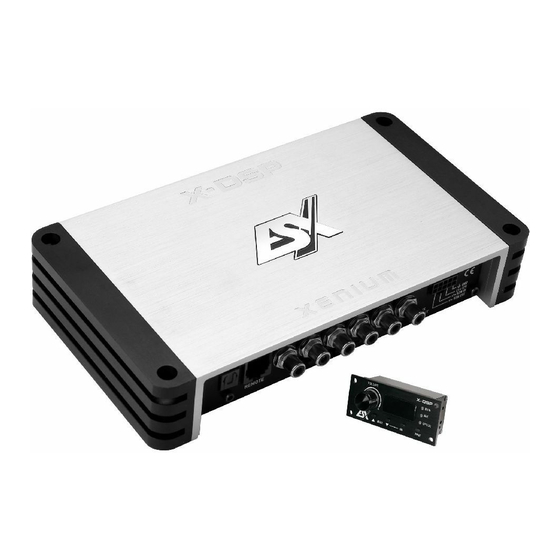
FUNKTIONSHINWEISE X– DSP DIGITAL SOUND PROCESSOR OPTICAL MAIN INPUT INPUT FUNKTIONEN UND BEDIENELEMENTE DES PROZESSORS SUB R SUB L REMOTE INPUT HIGH LEVEL INPUT PC CONNECT OUTPUT POWER X– DSP DIGITAL SOUND PROCESSOR OPTICAL MAIN INPUT INPUT SUB R SUB L REMOTE INPUT HIGH LEVEL... -
Seite 7: Funktionen Und Bedienelemente Der Fernbedienung
FUNKTIONSHINWEISE BELEGUNG X– DSP DIGITAL SOUND PROCESSOR KABELSATZ HOCHPEGEL-EINGÄNGE OPTICAL MAIN INPUT INPUT SUB R SUB L BRAUN/SCHWARZ WEISS REMOTE SUB R – INPUT FRONT L + HIGH LEVEL INPUT BRAUN WEISS/SCHWARZ SUB R + FRONT L – ORANGE/SCHWARZ GRAU SUB L –... -
Seite 8: Installation Der Dsp-Software
Die Installation benötigt ca. 25 MB freien Speicherplatz. Prinzipbedingt sollte dafür ein tragbarer Laptop-Computer verwendet werden. 2. Nachdem Sie die X-CONTROL 2 Software unter http://www.audiodesign.de/esx/dsp heruntergeladen haben, entpacken Sie zu- nächst die heruntergeladene „.rar“-Datei mit einer geeigneten Software wie beispielsweise WinRAR auf Ihrem PC. - Seite 9 FUNKTIONSHINWEISE Klicken Sie auf Click here to test um die Verbindung zum DSP-Gerät zu prüfen Wurde der Test erfolgreich durchgeführt erscheinen 4 Häkchen in den Checkboxen. Drü- cken Sie dann auf „[OK] Click here to start“ um fortzufahren. Sollte eines der Häkchen bei einer Checkbox nicht erscheinen, liegt ein Problem vor wel- ches zu einer Fehlfunktion führen kann.
-
Seite 10: Bedienoberfläche Der Software
FUNKTIONSHINWEISE BEDIENOBERFLÄCHE DER SOFTWARE Hier können Sie unzählige Einstellungen vornehmen und an Ihr Soundsystem anpassen, welche in Echtzeit über den DSP-Gerät sofort hörbar sind. Sobald Sie mit der Konfiguration eines Settings fertig sind, kann dieses auf den einen Speicherplatz im DSP-Gerät übertra- gen werden. - Seite 11 FUNKTIONSHINWEISE Unter „PRESETS ON THE DEVICE“, können Sie die Speicherplätze (POS1 - POS10) für die einzelnen Settings auf dem DSP- FUNKTIONSHINWEISE Gerät auslesen, löschen oder belegen. Wählen Sie zunächst den Speicherplatz (POS1 - POS10), denn Sie bearbeiten oder auslesen möchten aus. WRITE*: Speichert die augenblicklich eingestellte Einstellungen (Setting) im DSP-Gerät auf dem zuvor ausgewählten Speicherplatz ab.
- Seite 12 FUNKTIONSHINWEISE Im Abschnitt „TIME ALIGNMENT“ finden Sie eine vereinfachte Mög- lichkeit, die Laufzeitkorrektur der einzelnen Kanäle von X-CONTROL 2 berechnen zu lassen, um das Soundsystem und das DSP-Gerät optimal auf die akustische Bühnenmitte auszurichten. Beachten Sie dazu die folgenden Schritte: •...
-
Seite 13: Technische Daten
ALLGEMEINE HINWEISE TECHNISCHE DATEN MODELL X-DSP Frequenzgang –3dB 5 Hz - 20 kHz Signal-Rauschabstand > 110 dB Kanaltrennung > 60 dB Klirrfaktor (THD&N) 0,05% Eingangsempfindlichkeit 5 - 0,3 V Eingangsimpedanz > 47 kOhm DSP-Prozessor Cirrus Logic Single Core 32 bit, 8-Kanal, 192 kHz Signalausgänge 8 x Cinch/RCA Signaleingänge... -
Seite 14: Fehlerbehebung
FEHLERBEHEBUNG Fehler: keine Funktion Ursache: Lösung: 1. Die Stromversorgungskabel sind nicht korrekt angeschlossen. Erneute Überprüfung 2. Die Kabel haben keinen elektrischen und mechanischen Kontakt. Erneute Überprüfung 3. Die Remote-Steuerleitung des Steuergeräts (Autoradio) ist nicht korrekt am Prozessor angeschlossen. Erneute Überprüfung 4. - Seite 15 FEHLERBEHEBUNG Fehler: „ERROR“-Meldung bei Verbindung zwischen DSP-Gerät und Computer Ursache: Lösung: 1. Der DSP-Prozessor ist nicht eingeschaltet Beheben Sie die Ursache Hinweis: Die POWER LED sowie die USB LED müssen blau leuchten Fehler: „The COM port could not open...“-Meldung bei Verbindung zwischen DSP-Gerät und Computer Ursache: Lösung: 1.
- Seite 30 NOTES...
- Seite 31 NOTES...