Inhaltsverzeichnis
Werbung
Verfügbare Sprachen
Verfügbare Sprachen
Quicklinks
Werbung
Inhaltsverzeichnis

Inhaltszusammenfassung für CookMax 90681007
- Seite 1 90681007 (XW01000*H01 / ) Handbuch cookmax, cookmax+ und start! sind Marken der PENTAGAST eG Am Ruhrstrauch 4, D-36100 Petersberg Tel: +49 (0) 66 1 / 93 48 3 – 0 / Fax: +49 (0) 66 1 / 93 48 3 - 25 info@pentagast.de...
- Seite 2 MANUALE ISTRUZIONI WORKBOOK HANDBUCH MANUEL D’ENTRETIEN ET INSTALLATION L’ uso e la manutenzione Use and maintenance instructions Bedienungs- und Wartungsanweisungen Emploi et entretien WASTE COOLERS 1 di 10...
- Seite 3 BOX RIFIUTI WASTE BOX XW01 XW02 2 di 10...
- Seite 4 XW03 3 di 10...
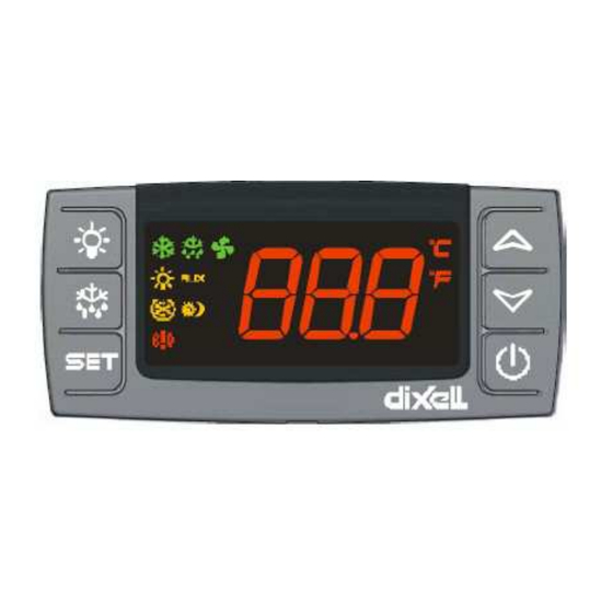
- Seite 5 AVVERTENZE GENERALI E DATI TECNICI RICEVIMENTO PANNELLO DI COMANDO MESSA IN FUNZIONE E DISMISSIONE PULIZIA E MANUTENZIONE RICERCA GUASTI XR70 CX : istruzioni per l'installazione ed uso GENERAL NOTICES RECEPTION CONTROL PANEL START-UP AND DISPOSAL OF UNIT CLEANING AND MAINTENANCE FAULT FINDING XR70 CX: INSTRUCTIONS FOR INSTALLATION AND USE ALLGEMEINE HINWEISE UND TECHNISCHE DATEN...
- Seite 6 Lasciar abbassare la temperatura prima di inserire nell’armadio. Leave warm foods to cool down before refrigerating. Lassen Sie warme Speisen abkühlen bevor Sie sie in den Kühlschrank stellen. Ne pas entrer de produits chauds directement dans l’armoire. Essere sicuri che tutti i cibi siano coperti. I prodotti devono sempre essere separati Make sure all products stored are covered.
-
Seite 7: Avvertenze Generali
ITALIANO AVVERTENZE GENERALI • Il presente manuale è stato realizzato per permettere una corretta installazione, messa a punto e manutenzione dell’apparecchio; è quindi di fondamentale importanza che : • Le avvertenze contenute nel presente libretto siano lette attentamente in quanto forniscono importanti indicazioni circa la sicurezza di installazione, d’uso e di manutenzione. - Seite 8 IMPORTANTE TUTTE LE OPERAZIONI DI SEGUITO CITATE DEBBONO ESSERE ESEGUITE IN CONFORMITÀ ALLE NORME DI SICUREZZA VIGENTI, SIA PER QUANTO RELATIVO ALL’ATTREZZATURA USATA CHE PER LE MODALITÀ OPERATIVE. ATTENZIONE PRIMA DI DAR CORSO A OPERAZIONI DI MOVIMENTAZIONE ASSICURARSI CHE LA CAPACITA’ DI SOLLEVAMENTO SIA ADEGUATA AL PESO DELL’APPARECCHIO IN QUESTIONE.
- Seite 9 IMPORTANTE PRIMA DI COLLEGARE L’APPARECCHIO ACCERTARSI CHE I DATI DI TARGA SIANO RISPONDENTI A QUELLI DELLA RETE ELETTRICA. LA TARGHETTA MATRICOLARE RECANTE I DATI ELETTRICI NECESSARI ALL’INSTALLAZIONE È POSIZIONATA SULL’APPARECCHIO IN CORRISPONDENZA DEL VANO MOTORE. L’INSTALLAZIONE DEVE ESSERE EFFETTUATA SECONDO LE ISTRUZIONI RIPORTATE ALLA PRESENTE SEZIONE DA PERSONALE PROFESSIONALMENTE QUALIFICATO.
-
Seite 10: Pulizia E Manutenzione
PULIZIA E MANUTENZIONE SOMMARIO 1.0- PULIZIA SETTIMANALE 2.0- MANUTENZIONE ORDINARIA 2.1 - BATTERIA CONDENSANTE 2.2 - ELETTROVENTILATORI 2.3 - CAVO DI ALIMENTAZIONE 3.0- FERMATE PROLUNGATE Questa sezione è dedicata all'utilizzatore finale ed è estremamente importante per il regolare funzionamento nel tempo dell'apparecchio. -
Seite 11: Ricerca Guasti
RICERCA GUASTI SOMMARIO: 1.0- ALTA PRESSIONE ANOMALA 2.0- BASSA PRESSIONE ANOMALA 3.0- GUASTO SONDE 4.0- APPARECCHIO RUMOROSO Ciò che segue vuole essere un aiuto nella ricerca della possibile soluzione ad alcune anomalie che si poterebbero manifestare sull'apparecchio, resta inteso che quanto riportato non copre totalmente la casistica delle possibilità. L'intervento di un dispositivo di sicurezza indica anomalia di funzionamento;... - Seite 12 dIXEL Istruzioni per installazione e uso 1591020070 modo da mantenere sempre una corretta ventilazione nella cella. Alla fermata del compressore, le ventole continuano a rimanere accese per il tempo Fon. Con Fon =0 le Controllori digitali con gestione sbrinamento, ventole ventole restano ferme con compressore spento.
- Seite 13 dIXEL Istruzioni per installazione e uso 1591020070 CCS Set point per ciclo continuo: (-50÷150°C) durante il ciclo continuo viene utilizzato 6.3 PER AVVIARE UN CICLO DI SBRINAMENTO MANUALE questo set point. Per avviare un ciclo di sbrinamento, premere il pulsante COn Tempo compressore ON con sonda guasta: (0÷255 min) tempo in cui il almeno 2s.
- Seite 14 dIXEL Istruzioni per installazione e uso 1591020070 AH2 Differenziale per rientro allarme temperatura condensatore: (0,1÷25,5°C; 1÷45°F) 8.5 AVVIO CICLO DI SBRINAMENTO (i1F=dFr) Differenziale per rientro dell’allarme di temperatura di condensatore. Avvia un ciclo di sbrinamento se ci sono le condizioni. Al termine dello sbrinamento la Ad2 Ritardo allarme temperatura condensatore: (0÷255 min) intervallo di tempo tra la regolazione normale riprende solo se l’ingresso digitale non è...
-
Seite 15: Dati Tecnici
dIXEL Istruzioni per installazione e uso 1591020070 Mess. Causa Uscite 17. VALORI STANDARD "P4" Sonda 4 guasta Allarme condensatore non gestito Descrizione Range Valore Label "HA" Allarme di alta temper. Non modificata Set point LS - US -5.0 - - - "LA"... -
Seite 16: General Notices
GENERAL NOTICES This manual has been prepared to enable a correct installation, regulation and maintenance of the appliance; it is therefore of fundamental importance that : - the warnings contained in this booklet are read carefully as they supply essential indications regarding the safety of the installation, use and maintenance. - Seite 17 IMPORTANT ALL THE OPERATIONS INDICATED BELOW MUST BE PERFORMED IN RESPECT OF EXISTING SAFETY REGULATIONS, BOTH FOR THE EQUIPMENT IN USE AND FOR THE OPERATING PROCEDURES. WARNING BEFORE BEGINNING HANDLING OPERATIONS ENSURE THAT THE LIFTING CAPACITY IS SUFFICIENT FOR THE APPLIANCE IN QUESTION. 2.0 HANDLING 1.1 - HANDLING with FORK LIFT or SIMILAR 1.1.1 - Insert the forks into the side of back of the wooden pallet supplied with the appliance.
-
Seite 18: Disposal Of Unit
IMPORTANT BEFORE CONNECTING THE APPLIANCE CHECK THAT THE DATA ON THE SERIAL PLATE CORRESPOND TO THE ACTUAL ELECTRICAL SUPPLY. THE SERIAL PLATE GIVING THE ELECTRICAL DATA REQUIRED IN THE INSTALLATION IS FOUND INSIDE THE APPLIANCE ON THE TOP RIGHT-HAND SIDE. THE INSTALLATION MUST BE MADE ACCORDING TO THE INSTRUCTIONS GIVEN IN THIS SECTION, BY PROFESSIONALLY QUALIFIED PERSONNEL. -
Seite 19: Cleaning And Maintenance
CLEANING AND MAINTENANCE CONTENTS: 0.0 WEEKLY CLEANING 1.0 ROUTINE MAINTENANCE 2.1 - CONDENSING COIL 2.2 - FANS 2.3 - POWER CABLE 2.0 LONG SHUTDOWNS This section has been dedicated to the end-user and is extremely important for the appliance to work correctly in the long-term. -
Seite 20: Fault Finding
FAULT FINDING 1.0 - ABNORMALLY HIGH PRESSURE 2.0 - ABNORMALLY LOW PRESSURE 3.0 - SENSOR FAILURE 4.0 – THE APPLIANCE IS NOISY The following list has been prepared as a guideline to the search of possible remedies to some anomalies that could be found in the appliance, it should be understood that this list does not cover all possible cases. - Seite 21 dIXEL Installing and Operating Instructions 1592020570 3.3.2 Cyclical activation of the fans with compressor off. When Fnc = c-n or c-Y (fans in parallel to the compressor), by means of the Fon and FoF parameters Digital controller with defrost and fans management the fans can carry out on and off cycles even if the compressor is switched off.
- Seite 22 dIXEL Installing and Operating Instructions 1592020570 P3P Third probe presence (P3): n= not present:, the terminal operates as digital input.; y= 6.2 HOW TO SEE THE SETPOINT present:, the terminal operates as third probe. Push and immediately release the SET key: the display will show the O3 Third probe calibration (P3): (-12.0÷12.0°C;...
- Seite 23 dIXEL Installing and Operating Instructions 1592020570 ALU MAXIMUM temperature alarm: (SET÷110°C; SET÷230°F) when this temperature is reached PbC Type of probe: it allows to set the kind of probe used by the instrument: PbC = PBC probe, ntc the alarm is enabled, after the “ALd” delay time. = NTC probe.
- Seite 24 dIXEL Installing and Operating Instructions 1592020570 Resolution: 0,1 °C or 1°C or 1 °F (selectable); Accuracy (ambient temp. 25°C): ±0,7 °C ±1 digit 12.1 PROBE CONNECTION The probes shall be mounted with the bulb upwards to prevent damages due to casual liquid 16.
- Seite 25 dIXEL Installing and Operating Instructions 1592020570 Labe Name Range °C/°F Level ALc Temperat. alarms configuration rE= related to set; Ab = absolute ALU MAXIMUM temperature alarm Set÷110.0°C; Set÷230°F ALL Minimum temperature alarm -50.0°C÷Set/ -58°F÷Set -50.0 AFH Differential for temperat. alarm recovery (0,1°C÷25,5°C) (1°F÷45°F) ALd Temperature alarm delay 0 ÷...
-
Seite 26: Allgemeine Hinweise
ALLGEMEINE HINWEISE Das vorliegende Handbuch dient zur korrekten Installation, Einstellung und Wartung des Geräts; deshalb sollte man unbedingt d arauf achten, dass: - die folgenden Hinweise aufmerksam durchgelesen werden, da sie wichtige Anweisungen zur Sicherheit bei der Installation, dem Gebrauch und der Wartung liefern. - das vorliegende Handbuch und das elektrische Schema an einem sicheren Ort aufbewahrt und dem Bediener zwecks Nachschlagen zur Verfügung gestellt werden. -
Seite 27: Wichtige Hinweise
WICHTIG ALLE IM FOLGENDEN AUFGEFÜHRTEN ARBEITSGÄNGE MÜSSEN DEN GELTEN SICHERHEITSNORMEN GEMÄSS DURCHGEFÜHRT WERDEN. DIES GILT SOWOHL FÜR DIE VERWENDETE AUSRÜSTUNG ALS AUCH FÜR DIE BEDIENUNGSWEISE ACHTUNG SICH VOR DER HANDHABUNG VERGEWISSERN, OB DAS ANHEBUNGSVERMÖGEN DEM GEWICHT DER BETREFFENDEN EINHEIT ANGEMESSEN IST. 2.0 –... -
Seite 28: Bevor Man Die Lebensmittel Einführt, Das Gerät In Betriebszustand Bringen
WICHTIG BEVOR MAN DAS GERÄT ANSCHLIESST, SOLLTE MAN SICH VERGEWISSERN, DASS DIE DATEN DES LEISTUNGSSCHILDES DENEN DES STROMNETZES ENTSPRECHEN. DAS GERÄTESCHILD, AUF DEM DIE FÜR DIE INSTALLATION ERFORDERLICHEN ELEKTRISCHEN DATEN ANGEGEBEN SIND, IST IN DER ZELLE AUF DER MOTORBEREICH POSITIONIERT. DIE INSTALLATION MUSS GEMÄSS DEN ANGABEN DES VORLIEGENDEN ABSCHNITTS VOM QUALIFIZIERTEN FACHPERSONAL DURCHGEFÜHRT WERDEN. -
Seite 29: Reinigung Und Wartung
REINIGUNG UND WARTUNG INHALT: 1.0 - WÖCHENTLICHE REINIGUNG 2.0 – ALLEGEMEINE WARTUNGARIA 2.1 - KONDENSATIONSBATTERIE 2.2 - ELEKTROVENTILATOREN 2.3 – ANSCHLUSSKABEL 3.0 – LÄNGERE STILLSTANDSZEITEN Dieser Abschnitt betrifft den Endverbraucher und ist für den dauerhaften und Vorschriftmäßigen Betrieb des Geräts von äußerster Wichtigkeit. -
Seite 30: Störungssuche
STÖRUNGSSUCHE 1.0 – UNGEWÖHNLICHER HOCHDRUCK 2.0 – UNGEWÖHNLICHER TIEFDRUCK 3.0 – FÜHLERDEFEKT 4.0 - GERÄUCHVOLLES GERÄT Die im folgenden aufgeführten Punkte sollen bei der Lösung einiger das Gerät betreffenden Störungen behilflich sein. In diesem Handbuch sind selbstverständlich nicht alle Möglichkeiten aufgeführt. Die Einschaltung einer Sicherheitsvorrichtung ist Anzeichen einer Betriebsstörung;... -
Seite 31: Allgemeine Beschreibung
* W enn die Verdampfer-Temperatur über dem Vorgabewert „FSt“ liegt, wird das Kühlstellenregler mit Abtau- und Gebläse-Steuerung Gebläse ebenfalls gestoppt. Damit nur aussreichend kühle Luft im Raum verteilt wird. sowie ein 2. konfig. Relais (z.B. Licht EIN/AUS) XR70CX Anlauf-Verzögerung des Gebläse: Nach der Abtauung wird das Gebläse nochmals für die Zeit Fnd verzögert. -
Seite 32: Höchste Und Tiefste Temperatur
Modus Bedeutung Das Hilfs-Relais kann nur über den digitalen Eingang aktiviert und Bem.: Die neue Vorgabe wird in jedem Fall gespeichert. deaktiviert werden. Vorausgesetzt Par. oA1 = AUS + Par. i1F = 6.6.2 EINEN PARAMETER IN DER ERSTEN EBENE SICHTBAR MACHEN AUS. - Seite 33 Raum-Fühler grösser Fct ist, sind die Gebläse immer aktiviert. Eine genaue CCt Dauer des Schockgefrierens: (0.0÷24.0h; Auflösung 10min). Zeitvorgabe für Beschreibung finden Sie in Kapitel 3.3.1 ! den Verdichterdauerlauf, welcher über Fronttaste gestartet wird. Beispielsweise FSt Gebläse-Stopp Temperatur (-50÷50°C) wenn die Verdampfer-Temperatur bei frischer Bestückung der Kühlzelle mit W are, welche schnell runtergekühlt oberhalb dieser Temperaturgrenze liegt, werden die Gebläse gestoppt.
- Seite 34 Con i1F=PAL erlaubte Pressostat-Schaltungen im Zeit-Intervall “did”: 8.8 POLARITÄT DES DIGITALEN EINGANG sobald nPS Presssostat-Schaltungen im Zeitinervall did erreicht wurden, wird Polarität des dig. Eingangs: “i1P”. Bei Par. i1P=CL : aktiv bei geschlossenen Kontakt; „CA“ angezeigt und die Regelung gestoppt (Eigenschutz, z.B. bei Kältemittel- Bei Par.
-
Seite 35: Technische Daten
14. ALARM – MELDUNGEN 16.1 VERDICHTER-RELAIS 8A OD. 16A - 120VAC OD. 230 VAC Meld. Ursache Ausgänge "P1" Raumfühler defekt oder fehlt Verdichter-Regelung gemäss Par. “COn” und “COF” "P2" Verdampfer-Fühler defekt oder fehlt Abtauungen über die Zeit "P3" 3. Fühler defekt oder fehlt Regelung unbeeinflusst "P4"... -
Seite 36: Parameter - Werksvorgaben
Nummer der Parameter-Tabelle Nur Anzeige 17. PARAMETER – WERKSVORGABEN Type: XR70CX–xx2xx, XR70CX–xx3xx Die Parameterliste ersetzt nicht das gesamte Handbuch ! Eine ausführliche Erläuterung der Parameter finden Sie im Kapitel „Parameter-Beschreibung“. Label Beschreibung Vorgabe-Bereich Vorgab Eben Sollwert LS - US -5.0 - - - Hysterese für Verdichter-Regelung (0,1°C÷25,5°C) (1°F÷45°F)