Phoenix Contact 2904472 Betriebsanleitung Für Den Elektroinstallateur
Profinet-bus-ankoppler
Quicklinks
FRANÇAIS
Coupleur de bus PROFINET pour appareils système INTERFACE
1. Consignes de sécurité
• Respectez les consignes de sécurité de l'industrie électrotechnique et celles des organisations
professionnelles.
• Le non-respect de ces consignes peut entraîner la mort, des blessures graves ou d'importants
dommages matériels!
• La mise en service, le montage, les modifications et les extensions ne doivent être confiés qu'à
des électriciens qualifiés!
• Fonctionnement en armoire électrique fermée selon IP54 !
• Avant de commencer les travaux, mettez l'appareil hors tension!
• Pendant le fonctionnement, certaines pièces des appareillages électriques sont soumis à une ten-
sion dangereuse !
• Ne jamais déposer les capots de protection des appareillages électriques lorsque ceux-ci sont en
service.
• Remplacer impérativement l'appareil dès la première défaillance !
• Les réparations de l'appareil, et plus particulièrement l'ouverture du boîtier, ne doivent être effec-
tuées que par le fabricant.
• Conservez impérativement ce manuel d'utilisation !
2. Brève description
Le module de couplage de bus (passerelle) est destiné au raccordement des appareils de la gamme système
Interface à un réseau PROFINET.
Jusqu'à 32 appareils (esclaves) peuvent être raccordés.
L'affectation des données de process est adaptable via un DTM de passerelle et individuellement aux besoins
de votre application. Le DTM permet également une intégration aisée dans les environnements FDT.
Vous trouverez le DTM de passerelle sur Internet à l'adresse phoenixcontact.com.
La configuration de l'adresse est réalisée par l'intermédiaire d'un bouton ou via un PC ou une clé mémoire raccordé
au S-PORT.
3. Conseils relatifs au raccordement
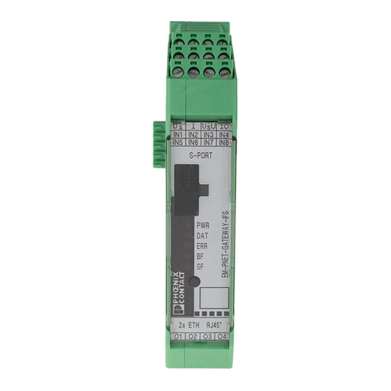
3.1 Éléments de commande ()
1
Entrées IN1 ... IN4
2
Entrées IN5 ... IN8
3
PORT S
Raccordement pour adaptateur de programmation
4
LED PWR
Etat de l'appareil
5
LED DAT
Communication IFS
6
LED ERR
Erreur appareil ou process
7
LED BF
Communication PROFINET
8
LED SF
Erreur station
9
Bouton de réglage du mode IP
10
2x interfaces RJ45
11
LED LNK
Link
12
LED Baud
Vitesse de transmission
13
Sorties O1 à O4
Pied métallique de verrouillage pour fixation sur le profilé
14
15
Raccordement pour connecteur sur profilé TBUS
16
Entrée: tension de service U
S
17
Tension d'alimentation pour les sorties O1...O4
IMPORTANT
Les entrées tension de commande de mesure et tension de commande doivent être alimentées par des
alimentations SELV fournissant un courant de sortie maximum de 8 A.
IMPORTANT
Utiliser des câbles blindés afin d'éviter le couplage inductif ou capacitif des perturbations dans le cas de
lignes de commande particulièrement longues.
IMPORTANT
Si plusieurs fils sont branchés sur une borne, utiliser des fils ayant une même section de conducteur.
3.2 Montage ()
Les appareils ne doivent être montés/démontés au niveau du connecteur sur profilé TBUS qu'à l'état
hors tension.
Connecteur sur profilé TBUS
Le connecteur sur profilé TBUS assure la communication système INTERFACE et/ou l'alimentation en tension
de différents appareils système INTERFACE.
L'utilisation du connecteur sur profilé TBUS pour alimenter les modules n'est possible qu'avec les appa-
reils 24 V DC.
Assembler le nombre requis de connecteurs sur profilé TBUS (réf. : 2707437).
Tenir compte, lors de la mise en place de la PASSERELLE sur le profilé, de l'orientation correcte par rapport
au TBUS.
L'alimentation en tension est assurée au niveau de la passerelle ou d'un module d'alimentation. Tenir compte
de l'ampérage admissible !
ENGLISH
PROFINET bus coupler for INTERFACE system devices
1. Safety notes
• Please observe the safety regulations of electrical engineering and industrial safety and liability
associations.
• Disregarding these safety regulations may result in death, serious personal injury or damage to
equipment!
• Startup, mounting, modifications, and upgrades should only be carried out by a skilled electrical
engineer!
• Operation in a closed control cabinet according to IP54!
• Before working on the device, disconnect the power!
• During operation, parts of electrical switching devices carry hazardous voltages!
• During operation, the protective covers must not be removed from the electric switchgear!
• In the event of an error, replace the device immediately!
• Repairs to the device, particularly the opening of the housing, must only be carried out by the
manufacturer.
• Keep the operating instructions in a safe place!
2. Short description
The bus coupler module (gateway) is used for connecting devices of the Interface system range to a PROFINET net-
work.
Up to 32 devices (slaves) can be connected.
The assignment of the process data can be individually adapted to your application requirements using the
gateway DTM. The DTM is also used for easy integration in an FDT environment.
The gateway DTM can be found on the INTERNET at phoenixcontact.com.
The address is set using a button or a PC or memory stick connected to the S-PORT.
3. Connection notes
3.1 Operating elements ()
1
Inputs IN1 ... IN4
2
Inputs IN5 ... IN8
3
S-PORT
Connection for programming adapter
4
LED PWR
Device status
5
LED DAT
IFS communication
6
LED ERR
Device or process error
7
LED BF
PROFINET communication
8
SF LED
Station error
9
Button for setting IP mode
10
2 RJ45 interfaces
11
LNK LED
Link
12
Baud LED
Baud rate
13
Outputs O1 to O4
Metal base latch for fixing to the DIN rail
14
15
Connection for TBUS DIN rail connector
16
Input: Operating voltage U
S
17
Supply voltage for outputs O1...O4
NOTE
Operate the rated control voltage and control voltage inputs with SELV power units that supply output
current of at most 8 A.
NOTE
In order to avoid inductive or capacitive coupling of noise emissions where long control wires are used,
we recommend the use of shielded conductors.
NOTE
If you want to connect multiple conductors to one terminal, you must use conductors with the same con-
ductor cross section.
3.2 Mounting ()
Installation/removal of the devices on/from the TBUS DIN rail connector may only be performed when no
voltage is applied.
TBUS DIN rail connector
The TBUS DIN rail connector makes the INTERFACE system communication and/or power supply of individual
INTERFACE system devices possible.
The use of the TBUS DIN rail connector for the supply of modules is only possible with 24 V DC devices.
Connect the required number of TBUS DIN rail connectors (Order No. 2707437) together.
When placing the gateway onto the DIN rail, make sure that it is aligned correctly with the TBUS.
Power is supplied on the gateway or a power terminal. Observe the permissible current carrying capacity.
DEUTSCH
PROFINET-Bus-Ankoppler für INTERFACE-Systemgeräte
1. Sicherheitshinweise
• Beachten Sie die Sicherheitsvorschriften der Elektrotechnik und der Berufsgenossenschaft!
• Werden die Sicherheitsvorschriften nicht beachtet, kann Tod, schwere Körperverletzung oder
hoher Sachschaden die Folge sein!
• Inbetriebnahme, Montage, Änderung und Nachrüstung darf nur von einer Elektrofachkraft ausge-
führt werden!
• Betrieb im verschlossenen Schaltschrank gemäß IP54!
• Schalten Sie das Gerät vor Beginn der Arbeiten spannungsfrei!
• Während des Betriebes stehen Teile der elektrischen Schaltgeräte unter gefährlicher Spannung!
• Schutzabdeckungen dürfen während des Betriebes von elektrischen Schaltgeräten nicht entfernt
werden!
• Wechseln Sie das Gerät nach dem ersten Fehler unbedingt aus!
• Reparaturen am Gerät, insbesondere das Öffnen des Gehäuses, dürfen nur vom Hersteller vorge-
nommen werden.
• Bewahren Sie die Betriebsanleitung auf!
2. Kurzbeschreibung
Das Bus-Ankoppelmodul (Gateway) dient dem Anschluss von Geräten der Interface-System-Familie an ein
PROFINET-Netzwerk.
Sie können bis zu 32 Geräte (Slaves) anschließen.
Die Belegung der Prozessdaten können Sie durch den Gateway-DTM individuell den Bedürfnissen Ihrer An-
wendung anpassen. Über das DTM erfolgt auch die einfache Integration in FDT-Umgebungen.
Das Gateway-DTM finden Sie im Internet unter phoenixcontact.com.
Die Einstellung der Adresse erfolgt durch einen Taster oder durch ein am S-PORT angeschlossenen PC oder
Speicherstick.
3. Anschlusshinweise
3.1 Bedienelemente ()
1
Eingänge IN1 ... IN4
2
Eingänge IN5 ... IN8
3
S-PORT
Anschluss für Programmieradapter
4
LED PWR
Gerätestatus
5
LED DAT
IFS-Kommunikation
6
LED ERR
Geräte- oder Prozessfehler
7
LED BF
PROFINET-Kommunikation
8
LED SF
Stationsfehler
9
Taster zum Einstellen des IP-Modus
10
2x RJ45-Schnittstellen
11
LED LNK
Link
12
LED Baud
Baud Rate
13
Ausgänge O1 bis O4
Metall-Fußriegel zur Befestigung auf der Tragschiene
14
15
Anschluss für Tragschienen-Busverbinder TBUS
16
Eingang: Betriebsspannung U
S
17
Versorgungsspannung für die Ausgänge O1...O4
ACHTUNG
Betreiben Sie die Bemessungssteuerspannungs- und Steuerspannungseingänge mit SELV-Netzteilen,
die einen Ausgangsstrom von maximal 8 A liefern.
ACHTUNG
Verwenden Sie abgeschirmte Leitungen, so vermeiden Sie die induktive oder kapazitive Einkopplung
von Störimpulsen bei langen Steuerleitungen.
ACHTUNG
Verwenden Sie Leiter mit gleichem Leiterquerschnitt, wenn Sie mehrere Leiter an einer Klemme anschließen.
3.2 Montage ()
Die Montage/Demontage der Geräte auf den Tragschienen-Busverbinder TBUS darf nur im spannungs-
losen Zustand erfolgen.
Tragschienen-Busverbinder TBUS
Der Tragschienen-Busverbinder TBUS ermöglicht die INTERFACE-System-Kommunikation und/oder die
Spannungseinspeisung einzelner INTERFACE-Systemgeräte.
Die Nutzung des Tragschienen-Busverbinders TBUS zur Versorgung der Module ist nur in Verbindung
mit 24 V DC-Geräten möglich!
Stecken Sie die benötigte Anzahl Tragschienen-Busverbinder TBUS (Art.-Nr.: 2707437) zusammen.
Achten Sie beim Aufsetzen des Gateways auf die Tragschiene auf die korrekte Ausrichtung zum TBUS.
Die Spannungseinspeisung erfolgt am Gateway oder einer Einspeisungsklemme. Beachten Sie die zulässige
Stromtragfähigkeit!
PHOENIX CONTACT GmbH & Co. KG
Flachsmarktstraße 8, 32825 Blomberg, Germany
Fax +49-(0)5235-341200, Phone +49-(0)5235-300
phoenixcontact.com
MNR 9067406
DE
Betriebsanleitung für den Elektroinstallateur
(Originalbetriebsanleitung)
EN
Operating instructions for electrical personnel
(original operating instructions)
FR
Manuel d'utilisation pour l'électricien
(instructions de service originales)
EM-PNET-GATEWAY-IFS
16
17
1
2
PH
OE
Fla
NI X
32 82
ch sm
CO
ar kts
NT
AC
5 Bl
om
tr. 8
T Gm
E M
15
be rg
, Ge
bH
& Co
-P N
rm
O rd
an y
. KG
E T
-N
o .:
-G
A T
ww
2 9
E W
w. ph
0 4
oe nix
4 7
A Y
co nta
2
-I F
ct. co
S
m
3
O
O
IN 4
X X
U
IN 3
S
IN 8
/X X
IN 2
IN 7
14
U
S
IN 1
IN 6
In 5
O R
T
S -P
4
5
R
PW
6
T
DA
R
ER
BF
7
SF
T/
SE
RE
T
SE
8
13
5"
J4
"R
E TH
O 4
O 3
2x
O 2
O 1
12
9
11
10
IN1
U
GND
S
EPROM
IN2
IFS-
IN3
24V
DC
IN4
Port
IN
Reset
IN5
IN6
IN7
RJ45
IN8
µController
O1
T O
RJ45
U
O
O2
S
OUT
O3
O4
PWR
DAT
ERR
BF
SF
IFS
TBUS
A
C
B
D
E
© PHOENIX CONTACT 2018
PNR 106283 - 02
2018-11-02
2904472
DNR 8316166 - 02

Verwandte Anleitungen für Phoenix Contact 2904472


Inhaltszusammenfassung für Phoenix Contact 2904472
- Seite 1 PHOENIX CONTACT GmbH & Co. KG FRANÇAIS ENGLISH DEUTSCH Flachsmarktstraße 8, 32825 Blomberg, Germany Coupleur de bus PROFINET pour appareils système INTERFACE PROFINET bus coupler for INTERFACE system devices PROFINET-Bus-Ankoppler für INTERFACE-Systemgeräte Fax +49-(0)5235-341200, Phone +49-(0)5235-300 phoenixcontact.com MNR 9067406 2018-11-02 1.
- Seite 2 22,5 mm / 99 mm / 114,5 mm Conformité / Homologations Conformance/Approvals Konformität / Zulassungen Homologations Approvals Zulassungen Normes/prescriptions Standards/specifications Normen/Bestimmungen EN 61131-2 © PHOENIX CONTACT 2018 PNR 106283 - 02 DNR 8316166 - 02...
- Seite 3 PHOENIX CONTACT GmbH & Co. KG PORTUGUÊS ESPAÑOL ITALIANO Flachsmarktstraße 8, 32825 Blomberg, Germany Acoplador de bus PROFINET para dispositivos de sistema INTERFACE Acoplador bus PROFINET para dispositivos del sistema INTERFACE Accoppiatore bus PROFINET per dispositivi del sistema INTERFACE Fax +49-(0)5235-341200, Phone +49-(0)5235-300 phoenixcontact.com...
- Seite 4 22,5 mm / 99 mm / 114,5 mm Conformidade / Certificações Conformidad / Homologaciones Conformità/omologazioni Certificações Homologaciones Omologazioni Normas/Disposições Normas/disposiciones Norme/disposizioni EN 61131-2 © PHOENIX CONTACT 2018 PNR 106283 - 02 DNR 8316166 - 02...
- Seite 5 PHOENIX CONTACT GmbH & Co. KG РУССКИЙ РУССКИЙ TÜRKÇE TÜRKÇE Flachsmarktstraße 8, 32825 Blomberg, Germany Устройство сопряжения шины PROFINET для INTRFACE sistem cihazları için PROFINET bus modülü Fax +49-(0)5235-341200, Phone +49-(0)5235-300 phoenixcontact.com MNR 9067406 2018-11-02 системных устройств INTERFACE 1. Güvenlik notları...
- Seite 6 22,5 mm / 99 mm / 114,5 mm Соответствие нормам /допуски Uygunluk / onaylar Сертификаты Onaylar Стандарты/нормативные документы Standartlar/teknik özellikler EN 61131-2 © PHOENIX CONTACT 2018 PNR 106283 - 02 DNR 8316166 - 02...
- Seite 7 中文 中文 PHOENIX CONTACT GmbH & Co. KG POLSKI POLSKI Flachsmarktstraße 8, 32825 Blomberg, Germany PROFINET 总线耦合器,适用于 INTERFACE 系统设备 Przyłącze magistrali PROFINET dla urządzeń systemo- Fax +49-(0)5235-341200, Phone +49-(0)5235-300 phoenixcontact.com MNR 9067406 2018-11-02 wych INTERFACE 1. 安全提示 Dokumentacja techniczno-ruchowa dla elektromontera •...
- Seite 8 22,5 mm / 99 mm / 114,5 mm 符合性/认证 Zgodność / świadectwa dopuszczenia 认证 Świadectwa kwalifikacji 标准 / 规格 Normy/przepisy EN 61131-2 © PHOENIX CONTACT 2018 PNR 106283 - 02 DNR 8316166 - 02...