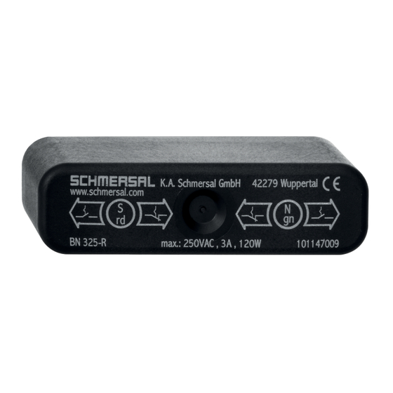
Werbung
Quicklinks
Montage- und Anschlussanleitung / Magnetschalter
Mounting and wiring instructions / Magnetic Switch
Instructions de montage et de câblage / Interrupteur à commande magnétique
Hinweis
deutsch
Der elektrische Anschluss darf nur von autorisiertem Fachpersonal
durchgeführt werden.
Die Konformitätserklärung nach Niederspannungsrichtlinie senden
wir Ihnen auf Wunsch gerne zu oder kann im Internet abgerufen
werden. Weitere technische Informationen entnehmen Sie bitte dem
Schmersal Hauptkatalog "Automatisierungstechnik".
Änderungen, die dem technischen Fortschritt dienen, vorbehalten.
Montage
• Die Montagelage ist beliebig
• Bei Verwendung mehrerer Magnetschalter Abbildungen auf
nächster Seite beachten (nur Index -1239, -1279 und -1279-2)
• Sensor und Magnet nicht in starken Magnetfeldern anbringen
• Eisenspäne fernhalten
• Sensor und Magnet keinen starken Vibrationen und Stößen
aussetzen
• Sensor und Magnet nicht als Anschlag benutzen
• Montageabstand zwischen zwei Systemen min. 30 mm
Notice
english
The electrical connection may only be carried out by an authorized
person.
The declaration of conformity according to the Low Voltage Directive
can be mailed to you on request or can be drawn from our website.
Further technical information can be found in the Schmersal Main
Catalogue "Automation technology".
Subject to technical modifications.
Mounting
• Any mounting position
• When using more than one magnet switch, consider figures next
page (only suffixes -1239, -1279 and -1279-2)
• Do not mount sensor and magnet in strong magnetic fields
• Ferrous filings may reduce sensitivity
• Do not subject components to extreme vibration or shock
• Do not use sensor and magnet as an end-stop
• Mounting distance between two systems min. 30 mm
Remarque
français
Le raccordement électrique doit être effectué uniquement par du
personnel technique habilité.
Une attestation de conformité à la directive Basse Tension peut vous
être adressée sur simple demande ou obtenue via Internet. Pour
d'autres informations de nature technique, veuillez vous reporter au
Schmersal Catalogue principal "Technique de l'automatisation".
Sous réserve de modifications techniques.
Montage
• La position de montage est indifférente
• Lorsque plusieurs interrupteurs magnétiques sont utilisés,
se reporter à l'illustration page suivante
(seulement pour les suffixes -1239, -1279 et -1279-2)
• Ne pas monter l'interrupteur et l'aimant dans des champs
magnétiques de forte intensité
• Eviter la présence de limaille de fer
• Ne pas exposer l'interrupteur et l'aimant à des vibrations
et des chocs de forte amplitude
• Ne pas utiliser l'interrupteur et l'aimant comme butée
• Distance de montage minimum entre deux systèmes: 30 mm
Flachstecker
Flat plug
Raccord faston
c
Leitungsausgang
Cable outlet
Sortie de câble
Legende
a
Abschirmblech
Legend
Shielding plate
Légende
Tôle de protection
b
Flachstecker
Flat plug
Raccord faston
BN 325-r
BN 325-rG
PIN 1
M 4
b
PIN 2
a
85
30
b
M 4
a
d
ø 9
a
9
c
d
c
Leitungsausgang links
Cable outlet left
Sortie de câble à gauche
(Index -1279)
d
Leitungsausgang rechts
Cable outlet right
Sortie de câble à droite
(Index -1279-2)
1 / 2
9
LED
9
LED
Werbung

Inhaltszusammenfassung für schmersal BN 325-r
- Seite 1 The declaration of conformity according to the Low Voltage Directive ø 9 can be mailed to you on request or can be drawn from our website. Further technical information can be found in the Schmersal Main Catalogue “Automation technology”. Subject to technical modifications.
- Seite 2 Induktive Verbraucher (z.B. Schütze, Relais etc.) sind durch eine geeignete Beschaltung zu entstören. Adjustment english In order to actuate the BN 325-r/-rG magnetic switch, a north or south pole magnet should be used. The markings found on the ³ ³...


