Inhaltsverzeichnis
Werbung
Verfügbare Sprachen
Verfügbare Sprachen
Quicklinks
CARDIN ELETTRONICA spa
Via del lavoro, 73 - Z.I. Cimavilla
3 1 0 1 3
®
Tel:
Fax:
email (Italian):
email (Europe):
Http:
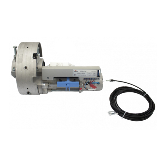
MOTORIDUTTORI PER SERRANDE 230V
230V GEARED MOTORS FOR ROLLING SHUTTERS
MOTORÉDUCTEURS 230V POUR VOLETS ET RIDEAUX ROULANTS
230V-GETRIEBEMOTOREN FÜR ROLLGITTERN UND ROLLTOREN
ITALIANO
Impianto tipo
Istruzioni per l'installazione
Scomposizione del motoriduttore
Installazione motoriduttore parte I
Installazione blocco a cordino
Collegamento elettrico
ENGLISH
Standard installation / technical data
Fastening the motor to the rolling shutter
Technical specifications
C o d o g n è
( T V )
I t a l y
+39/0438.404011
+39/0438.401831
Sales.office.it@cardin.it
Sales.office@cardin.it
www.cardin.it
Pagina
Pagina
Pagina
Pagina
Pagina
Pagina
Pagina
Pagina
Pagina
Pagina
Pagina
Page
Page
Page
Page
Page
Page
Page
Page
Page
Page
Page
RL
RL
Instruction manual
ZVL659.00
Questo prodotto è stato testato e collaudato nei laboratori della casa costruttrice, la quale ne ha verificato la perfetta
corrispondenza delle caratteristiche con quelle richieste dalla normativa vigente. This product has been tried and tested in
the manufacturer's laboratory who have verified that the product conforms in every aspect to the safety standards in force.
Ce produit a été testé et essayé dans les laboratoires du fabricant. Pour l'installer suivre attentivement les instructions
230V
fournies. Dieses Produkt wurde in den Werkstätten der Herstellerfirma auf die perfekte Übereinstimmung seiner
Eigenschaften mit den von den geltenden Normen vorgeschriebenen getestet und geprüft. Este producto ha sido probado
Motors
y ensayado en los laboratorios del fabricante, que ha comprobado la perfecta correspondencia de sus características
con las contempladas por la normativa vigente. Dit product werd uitgeprobeerd en getest in het laboratorium van de
fabrikant, die heeft vastgesteld dat het product in alle opzichten voldoet aan de geldende veiligheidsnormen.
CRL170-CRL170E-CRL360DE
FRANÇAIS
2
4
4
5
5
5
6
7
7
7
24
DEUTSCH
2
Installationsbeispiel
9
9
10
10
10
11
12
12
12
24
Series
Model
CRL
170-170E-360DE 06-08-2019
Date
Page
2
Page
14
Page
14
Page
15
Page
15
Page
15
Page
16
Page
17
Page
17
Page
17
Page
24
Seite
2
Seite
19
Seite
19
Seite
20
20
Seite
20
Seite
21
Seite
22
Seite
22
Seite
22
Seite
24
Werbung
Inhaltsverzeichnis

Verwandte Anleitungen für Cardin Elettronica CRL Serie


Inhaltszusammenfassung für Cardin Elettronica CRL Serie
-
Seite 1: Inhaltsverzeichnis
CARDIN ELETTRONICA spa Date Instruction manual Series Model Via del lavoro, 73 – Z.I. Cimavilla ZVL659.00 170-170E-360DE 06-08-2019 3 1 0 1 3 C o d o g n è ( T V ) I t a l y Questo prodotto è stato testato e collaudato nei laboratori della casa costruttrice, la quale ne ha verificato la perfetta ®... -
Seite 2: Example D'installation
ESEMPIO D'INSTALLAZIONE - INSTALLATION EXAMPLE - EXEMPLE D'INSTALLATION - ANLAGENART LEGENDA NOMENCLATURE Motoriduttore Motoréducteur Fotocellula Cellule photoélectrique Interruttore a muro TA - TC / sblocco a cordino Commutateur du mur TA - TC / câble de déverrouillage Lampeggiatore esterno con antenna Clignoteur externe avec antenne Programmatore Programmateur... -
Seite 3: Descrizione Tecnica
Questo prodotto è stato progettato e fabbricato in tutte le sue non si riesce a rispettare i limiti, aumentare l'altezza della parti a cura della Cardin Elettronica la quale ne ha verificato gomma o modificare la tipologia del suo profilo. -
Seite 4: Verifiche Preliminari
Attrezzature: VERIFICHE PRELIMINARI 3 - trapano Prima di procedere all'esecuzione dell'impianto verificare che la 4 - punta da 10,5 mm struttura da automatizzare sia in perfetta efficienza nelle sue parti 5 - punta da 12 mm fisse e mobili e realizzata in conformità alla normativa vigente. 6 - chiave esagonale da 6 mm L’installazione di un’automazione su un impianto già... -
Seite 5: Installazione Motoriduttore Parte Ii Pagina
INSTALLAZIONE SBLOCCO A CORDINO • A questo punto i componenti d'installazione sull banco di lavoro saranno come indicato in figure 5. Fig. 8 Fig. 5 • Passare il cordino di sblocco "37" attraverso il foro "18" e farlo uscire dall'estremità sinistra del tubo di supporto serranda. Tagliare il cordino di sblocco elettrofreno con il tranciacavo "12"... -
Seite 6: Collegamento Elettrico
• Prevedere il percorso dei cavi di alimentazione e comando secondo Fig. 12 le necessità di applicazione. • Collegare il cavo 4 x 1 mm "44" alla morsettiera del motore. Il quarto filo giallo e verde va collegato all'apposito terminale di mass "45" sul motore. -
Seite 7: Fissagio Motoriduttore Alla Serranda
(fotocellule, coste sensibili ecc.); Dette verifiche devono essere documentate in quanto sono indispensabili per usufruire della garanzia come stipulate nelle Condizioni di Vendita Generale della Cardin Elettronica. REGOLAZIONE FINECORSA Attenzione! La regolazione delle finecorse va fatto con la serranda completamente chiusa ed il motore bloccato. -
Seite 8: General Safety Instructions
• This product and all its relative components has been designed instrument. and manufactured by Cardin Elettronica that has verified that the product conforms in every aspect to the safety standards in Frequently examine the installation for imbalance where applicable force. -
Seite 9: Preliminary Checks
Equipment: PRELIMINARY CHECKS - drill Before starting with the installation of the system check that the - 10,5 mm drill bit structure which is to be automated is in good working order and - 12 mm drill bit respects the local standards and regulations in force. - 6 mm Allen key Automating an existing system which has sliding or balancing - 17 mm spanner... -
Seite 10: Geared Motor Installation Part I
MANUAL RELEASE CABLE INSTALLATION • At this point the components on the work bench should look something like those indicated in figure 5. Fig. 8 Fig. 5 • Pass the release cable "37" through the hole "18" and thread it through the tube until it exits to the left or right of the shutter support shaft. -
Seite 11: Electrical Connection
• Work out the run of the power and command cables according to Fig. 12 the installation requirements . • Wire the 4 x 1 mm cable "44" to the motor's terminal board. The yellow and green earth wire should be wired to the specific terminal "45"... -
Seite 12: Adjusting The Travel Limits
(photoelectric cells, safety edges etc.); These checks must be written down as they are paramount in ADJUSTING THE TRAVEL LIMITS validating the guarantee as stipulated in Cardin Elettronica's General Sales Conditions. Attention! Adjustment of the travel limits must be carried out with the rolling shutter completely closed and the motor blocked. -
Seite 13: Consignes Générales De Sécurité
Ce produit a été étudié et construit entièrement par la Sté • assurer la conformité. Si l’on n’arrive pas à respecter les Cardin Elettronica qui a pris soin de vérifier la conformité limites, augmenter la hauteur du caoutchouc ou modifier de ses caractéristiques avec les exigences des normes en son profil. -
Seite 14: Matériel D'installation
Matériel: CONTRÔLES AVANT LE MONTAGE 3 - perceuse Avant la pose, vérifier que les parties, aussi bien fixes que mobiles, 4 - pointe de 10,5 mm de la structure à automatiser, fonctionnent parfaitement et que 5 - pointe de 12 mm celle-ci ait été... -
Seite 15: Installation Motoréducteur Partie I
INSTALLATION CORDON DE DÉBLOCAGE • Les composants d’installation sur le banc de travail sont ceux indiqués à la Fig. 5. Fig. 8 Fig. 5 • Passer le cordon de déblocage 37 au travers du trou 18 et le faire sortir sur la gauche du tube de support du volet. Couper le cordon de déblocage électrofrein au moyen du coupe-câble 12 en fonction de la position finale du manchon de déblocage manuel 32. -
Seite 16: Programmateur Électronique
• Prévoir le parcours des câbles d’alimentation et de commande en Fig. 12 fonction des nécessités d’application. • Raccorder le câble 4 x 1 mm , 44 au bornier du moteur. Le quatrième fil jaune et vert doit être raccordé à la borne de masse 45 du moteur. -
Seite 17: Fixation Motoréducteur Au Volet
- vérifier le niveau de charge des batteries. Ces contrôles doivent être documentés car ils sont indispensables pour volet entièrement fermé et le moteur bloqué. pouvoir bénéficier de la garanti comme indiqué dans le Conditions Fig. 21 Générales de Vente de Cardin Elettronica. -
Seite 18: Allgemeine Betrachtungen Zur Sicherheit
ATTENZIONE! IMPORTANTI ISTRUZIONI DI SICUREZZA ACHTUNG! WICHTIGE SICHERHEITSHINWEISE ES IST FÜR DIE PERSONENSICHERHEIT VON GRÖSSTER WICHTIGKEIT, DIESEN ANWEISUNGEN FOLGE ZU LEISTEN: VOR DER INSTALLATION SOLLTEN DIE NACHSTEHENDEN HINWEISE AUFMERKSAM GELESEN UND FÜR SPÄTERE VERWENDUNG AUFBEWAHRT WERDEN. BESONDERE AUFMERKSAMKEIT SOLLTE ALLEN IN DIESER ORIGINAL-BEDIENUNGSANLEITUNG ABGEBILDETEN WARN- UND HINWEISSCHILDERN GEWIDMET WERDEN. -
Seite 19: Verifiche Vorkontrollen
Werkzeuge: VORKONTROLLEN VERIFICHE 3 - Bohrmaschine Vor der Installation ist zu überprüfen, dass die zu automatisierende 4 - Bohrer 10,5 mm Einrichtung in ihren festen und beweglichen Teilen einwandfrei 5 - Bohrer 12 mm funktioniert und entsprechend den geltenden Richtlinien ausgeführt 6 - Sechskantschlüssel 6 mm wurde. -
Seite 20: Installation Getriebemotor Teil I
• An diesem Punkt entsprechen die Installationskomponenten auf INSTALLATION KABELSCHNUR-ENTRIEGELUNGSMECHANISMUS der Werkbank der Darstellung in Abbildung 5. Abb. 8 Abb. 5 • Führen Sie die Entriegelungskabelschnur "37" durch das Loch "18" und lassen Sie sie am linken Ende des Rollladenhalterohrs herauskommen. -
Seite 21: Elektrischer Anschluss
• Kalkulieren Sie entsprechend den Erfordernissen den Verlauf des Abb. 12 Strom- und Steuerkabels. • Schließen Sie das Kabel 4 x 1 mm "44" an die Klemmleiste des Motors an. Das vierte Kabel (gelb und grün) muss an die entsprechende Erdungsklemme "45"... -
Seite 22: Befestigung Des Getriebemotors An Dem Rollladen
- der Ladezustand der Batterien prüfen. anschrauben wie in Abb. 9) gezeigt. Diese Überprüfungen müssen dokumentiert werden, da sie für die Inanspruchnahme der Garantie unerlässlich sind um die in Abb. 21 den Allgemeinen Verkaufsbedingungen von Cardin Elettronica vereinbarte Garantie Anspruch zu nehmen zu können. - Seite 23 NOTES:...
-
Seite 24: Technische Eigenschaften
Rollgitter max. Höhe DIMENSIONI D’INGOMBRO - OVERALL DIMENSIONS - DIMENSIONS D'ENCOMBREMENT - AUßENABMESSUNGEN CRL 170 CRL 170 E CRL 360 DE CRL 180 E CARDIN ELETTRONICA spa Via del lavoro, 73 – Z.I. Cimavilla 31013 Codognè (TV) Italy Tel: +39/0438.404011 Fax: +39/0438.401831 ®...