
Verwandte Anleitungen für Hifonics Triton Serie


Inhaltszusammenfassung für Hifonics Triton Serie
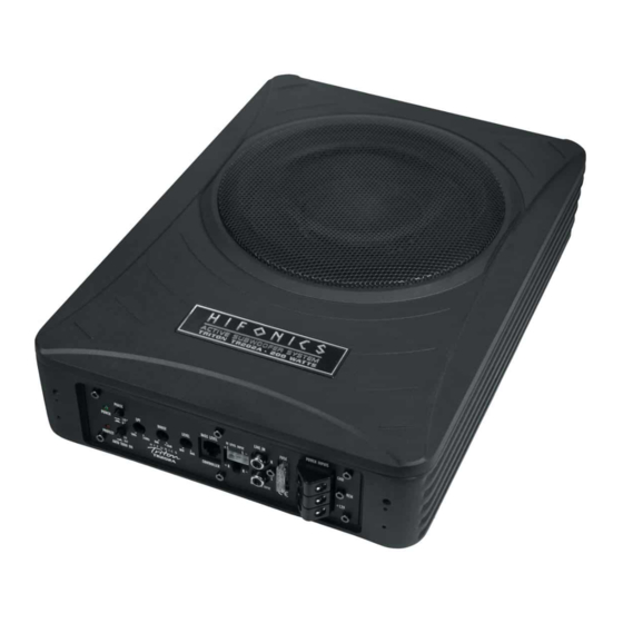
- Seite 1 BEDIENUNGSANLEITUNG USER’S MANUAL MODE D’EMPLOI MANUALE D’USO MANUAL DE USO ACTIVE SUBWOOFER SYSTEM TR202A...
- Seite 2 INHALTSVERZEICHNIS TABLE OF CONTENT TABLE DES MATIÈRES SOMMARIO INDICE BEDIENUNGSANLEITUNG USER’S MANUAL MODE D’EMPLOI MANUALE D´USO MANUAL DE USO...
-
Seite 3: Technische Daten
Bitte lesen Sie die Bedienungsanleitung vollständig durch, bevor Sie mit der Instal- lation beginnen und den Verstärker in Betrieb nehmen. TECHNISCHE DATEN TR202A Ausgangsleistung RMS 1 x 100 W Ausgangsleistung Max. 1 x 200 W Tiefpassfilter 50 – 150 Hz @ 12 dB/Oktave Subsonicfilter 20 Hz fest Phasen-Schalter... -
Seite 4: Installation
INSTALLATION 1. Befestigen Sie das Gerät im Fahrzeug wie unten gezeigt 2. Achten Sie bei der Installation des Geräts darauf, dass keine serienmäßig im Fahrzeug vorhandenen Teile wie z.B. Kabel, Bordcomputer, Sicherheitsgurte, Tank oder ähnliche Teile beschädigt bzw.entfernt werden. SCHUTZSCHALTUNG Die POWER LED (Abb. -
Seite 5: Phasen-Umschalter
HOCHPEGELEINGANG Der Hochpegeleingang (HI LEVEL INPUT, Abb. 1, 7) dient zur Ansteuerung des Verstärkers mittels Laut- sprecherkabel, falls Ihr Steuergerät (Autoradio) nicht über Vorverstärker-Ausgänge (Cinch-Ausgänge) verfügt. Verlängern Sie dazu die entsprechenden Lautsprecherkabel, die aus Ihrem Steuergerät führen mit geeigneten hochwertigen Lautsprecherkabeln bis zum Einbauort des Verstärkers. Verbinden Sie dann jeweils die passen- den Lautsprecherkabel mit den Kabeln des beiliegenden HI LEVEL INPUT-Steckers wie unten beschrieben. - Seite 6 ABBILDUNG 1 Betriebs-/Schutzschaltungsanzeigen Phasenumschalter Regler für den Tiefpassfilter Regler für die Bassanhebung Eingangspegelregler Remote-Anschluß für die beiliegende Kabelbassferbedienung Hochpegeleingänge für Lautsprecherkabel, kommend vom Steuergerät Audiosignal-Eingänge Gerätesicherung 10. Einschaltautomatik-Schalter 11. Anschluss REMOTE für die Einschaltleitung vom Steuergerät oder der elektrischen Antenne 12.
-
Seite 7: Fehlerbehebung
FEHLERBEHEBUNG Falls Sie nach dem Einbau Probleme haben, befolgen Sie die nachfolgenden Verfahren zur Fehlerbeseitigung: Verfahren 1: Das Gerät auf ordnungsgemäße Anschlüsse überprüfen. Prüfen Sie, ob die POWER LED aufleuchtet. Leuchtet die POWER LED auf, bei Schritt 3 weitermachen, falls nicht, hier weitermachen. -
Seite 8: Specifications
Please read the user‘s manual carefully before the installation and the first operation of the device. SPECIFICATIONS TR202A Output Power RMS 1 x 100 W Output Power Max. 1 x 200 W Lowpass Filter 50 – 150 Hz @ 12 dB/Octave Subsonic Filter 20 Hz fixed Phase-Switch 0° / 180° Bass Boost 0 –... -
Seite 9: Protection Circuit
INSTALLATION 1. Mount the device in the car as shown below. 2. Avoid any damage or removing of the components of the vehicle like wires, cables, board computer, seat belts, gastank or the like. PROTECTION CIRCUIT If the POWER LED (Fig. 1, 1) lits up blue, the device is in normal operation. If the PROTECT LED (Fig. 1, 1) lits up red, the device is overheated. -
Seite 10: Operating Elements
HI LEVEL INPUT The HI LEVEL INPUT (Fig. 1, 7) is suitable to connect the device input with speaker wires, if your head unit is not equipped with pre-amplifier RCA outputs. Extend therefor every regarding speaker cable from your head unit with appropriate speaker cables from your car audio retailer to the mounting location of the amplifier. - Seite 11 FIGURE 1 Power-/Protection-LED Phase switch Lowpass filter controller Bass Boost controller Gain level controller Remote jack for the included bass remote control Hi Level Input for speaker wires, coming from the head unit Stereo audio input Fuse 10. Auto Turn On switch 11.
-
Seite 12: Troubleshooting
TROUBLESHOOTING If you are having problems after installation follow the Troubleshooting procedures below. Procedure 1: Check the device for proper connections. Verify that POWER LED is on. If POWER LED is on skip to Step 3, if not continue. 1. Check the fuse of the device or the external fuse on battery positive cable. Replace if necessary. 2. - Seite 13 Veuillez s’il vous plait lire attentivement toutes les instructions d’installation avant que vous installiez l’amplificateur et le fassiez fonctionner. CARACTERISTIQUES TR202A Puissance de sortie RMS 1 x 100 W Puissance de sortie Max. 1 x 200 W Filtre passe-bas 50 – 150 Hz @ 12 dB/Octave Filtre subsonic 20 Hz Interrupteur de phase 0 / 180° 0° / 180° Boost des basses 0 –...
-
Seite 14: Circuit De Protection
INSTALLATION 1. Installer l´appareil dans la voiture comme décrit ci-dessous. 2. Éviter les dommages ou déplacer/retirer accidentellement les composants du véhicule comme les câbles, ordinateur de bord, ceinture de sécurité, réservoir d´essence etc... CIRCUIT DE PROTECTION Si la LED POWER (Fig. 1, 1) s´allume en bleu, l´appareil fonctionne correctement. Si la LED PROTECT (Fig.1, 1) s´allume en rouge, l´appareil est en surchauffe. - Seite 15 HI LEVEL INPUT (ENTRÉE HAUT NIVEAU) L´entrée haut niveau (HI LEVEL INPUT, Fig. 1, 7) est appropriée pour connecter les entrées de l‘appareil avec les fils des hauts-parleurs dans le cas où votre autoradio (source) ne serait pas équipé(e) de sorties RCA. Grâce aux câbles appropriés fournit par votre revendeur car audio pour les hauts-parleurs, prolonger les sorties de votre autoradio jusqu`à...
- Seite 16 FIGURE 1 LED de protection/d´alimentation Interrupteur de phase Régulateur du filtre passe-bas Régulateur de booster des basses Régulateur du niveau d’entrée Terminal de connexion pour la commande à distance du grave Entrée ligne haut niveau Entrée audio stéréo Fusible 10. Interrupteur de fonction allumage automatique 11.
-
Seite 17: Dépannage
DÉPANNAGE Si vous éprouvez des difficultés après l’installation, appliquez les procédures de dépannage ci-dessous. Procédure 1: Vérifiez que les connexions de l’appareil sont bien mises. Vérifiez que le voyant POWER est allumé. Si c‘est le cas, passez à l‘étape 3, sinon poursuivez. 1. -
Seite 18: Dati Tecnici
Per favore leggere le istruzioni per il montaggio integralmente, prima di montare l’amplificatore e di metterlo in funzione. DATI TECNICI TR202A Potenza di uscita RMS 1 x 100 W Potenza di uscita Max. 1 x 200 W Filtro passa basso 50 – 150 Hz @ 12 dB/Ottava Filtro subsonic 20 Hz Interruttore di fase 0° / 180° Bass Boost 0 –... -
Seite 19: Circuiti Di Protezione
MONTAGGIO 1. Montare il dispositivo in auto come illustrato di seguito. 2. Evitare qualsiasi danno o la rimozione dei componenti del veicolo come fili, cavi, computer di bordo, le cinture di sicurezza, serbatoio o simili. CIRCUITI DI PROTEZIONE Se il LED POWER (Fig.1, 1) si illumina di blu, il dispositivo funzione correttamente.Se il LED PROTECT (Fig.1, 1) si illumina di rosso, il dispositivo e surriscaldato.In questo caso il circuito interno di protezione provvede a spegnere automaticamente il dispositivo. -
Seite 20: Elementi Di Comando
INGRESSO HI LEVEL L´ingresso alto livello è indicato (Fig. 1, 7) per connettere l´ingresso dell´apparecchio con I cavi degli altopar- lanti nel caso la vostra sorgente non sia equipaggiata di uscite RCA. Attraverso cavi adeguati forniti dal vostro rivenditore car audio, prolungate le uscite della sorgente fino a dove volete posizionare il vostro apparecchio. - Seite 21 FIGURI 1 LED della protezione/di accensione Interruttore di fase Regolatore di frequenza per il passa basso Regolatore dell´incremento dei bassi Regolatore livello d‘ingresso Ingresso telecomando controllo die bassi (telecomando incluso) Ingresso alto livello Ingresso audio stereo Fusible 10. Interruttore Auto Turn On 11.
-
Seite 22: Risoluzione Dei Problemi
RISOLUZIONE DEI PROBLEMI Se incontraste dei problemi dopo l’installazione,seguite le procedure per la localizzazione e la riparazione dei guasti elencate di sotto. Procedura 1: Controllate che l’apparecchio abbia i collegamenti adeguati. Controllate che la spia dell’ACCENSIONE sia accesa.Se la spia di ACCENSIONE è accesa,passare al numero 3, altrimenti continuare 1. -
Seite 23: Datos Técnicos
Lea completamente las instrucciones de montaje antes de proceder a montar el amplificador y ponerlo en funcionamiento. DATOS TÉCNICOS TR202A Potencia de salida RMS 1 x 100 W Potencia de salida Max. 1 x 200 W Filtro paso bajo 50 – 150 Hz @ 12 dB/octava Filtro subsónico 20 Hz Regulador de fase 0 / 180° 0°... -
Seite 24: Montaje
MONTAJE 1. Instale el aparato en el vehículo como se muestra a continuación. 2. Evite causar daños o alterar acidentalmente elementos originales del vehículo como cables, ordenador de a bordo, cinturones de seguridad etc. Tenga en cuenta la ubicación del depósito de combustible antes de realizar cualquier perforación. -
Seite 25: Elementos De Mando
HI LEVEL INPUT (ENTRADA DE ALTA) La entrada de alta (HI LEVEL INPUT, Fig. 1, 7) es adecuada para conectar la entrada de dispositivo con cable de altavoz si su unidad radio-CD no esta dotada de salidas de previo. Amplíe los cables de salida de la unidad radio-CD hasta la ubicaciòn del dispositivo con cable de altavoz adecuado que puede proporcionarle su instalador autorizado. - Seite 26 FIGURE 1 LED de protección/funcionamiento Interruptor de fase Regulador de frecuencia de transición paso bajo Regulador de Bass Boost Regulador de nivel de entrada Conector para bass remote (incluido) Entrada de alto nivel Entrada audio stereo Fusible 10. Interruptor de auto encendido 11.
-
Seite 27: Solución De Problemas
SOLUCIÓN DE PROBLEMAS Si tiene problemas después de la instalación,siga los procedimientos de solución de problemas descritos a continu- ación. Procedimiento 1: Verifique que el dispositivo esté bien conectado. Compruebe que esté encendida la luz de ALIMENTACIÓN (POW- ER). Si la luz de ALIMENTACIÓN (POWER) está encendida vaya al Paso 3, de otra manera,continúe. 1. - Seite 28 Audio Design GmbH Am Breilingsweg 3 · D-76709 Kronau/Germany Tel. +49 7253 - 9465-0 · Fax +49 7253 - 946510 www.audiodesign.de ©2015 Audio Design GmbH, All Rights Reserved...