Herunterladen Inhalt Inhalt Diese Seite drucken
AFRISO Minimelder-R Betriebsanleitung

AFRISO Minimelder-R Betriebsanleitung

Füllstandgrenzschalter
Inhaltsverzeichnis

Werbung

Verfügbare Sprachen
  • DE

Verfügbare Sprachen

  • DEUTSCH, seite 1
Betriebsanleitung
Operating instructions
Notice technique
Istruzioni per l'uso
Instrukcja eksploatacji
Minimelder-R
Maximelder-R
Copyright 2020 AFRISO-EURO-INDEX GmbH. Alle Rechte vorbehalten.
Version: 03.2020.0
ID: 900.000.0206

Werbung

Inhaltsverzeichnis
loading

Inhaltszusammenfassung für AFRISO Minimelder-R

  • Seite 1 Betriebsanleitung Operating instructions Notice technique Istruzioni per l’uso Instrukcja eksploatacji Minimelder-R Maximelder-R Copyright 2020 AFRISO-EURO-INDEX GmbH. Alle Rechte vorbehalten. Version: 03.2020.0 ID: 900.000.0206...
  • Seite 2: Füllstandgrenzschalter

    Betriebsanleitung Füllstandgrenzschalter Minimelder-R Maximelder-R mit Relais Copyright 2020 AFRISO-EURO-INDEX GmbH. Alle Rechte vorbehalten. Lindenstraße 20 74363 Güglingen Telefon +49 7135 102-0 Service +49 7135 102-211 Telefax +49 7135 102-147 info@afriso.com Version: 03.2020.0 www.afriso.com ID: 900.000.0206...
  • Seite 3 Über diese Betriebsanleitung Über diese Betriebsanleitung Diese Betriebsanleitung beschreibt die Füllstandgrenzschalter Minimelder-R und Maximelder-R (im Folgenden auch „Produkt“). Diese Betriebsanleitung ist Teil des Produkts. • Sie dürfen das Produkt erst benutzen, wenn Sie die Betriebsanleitung vollständig gelesen und verstanden haben.
  • Seite 4: Informationen Zur Sicherheit

    Sie alle im Zusammenhang mit diesem Warnsymbol beschriebenen Hinweise, um Unfälle mit Todesfolge, Verlet- zungen und Sachschäden zu vermeiden. Dieses Symbol warnt vor gefährlicher elektrischer Span- nung. Wenn dieses Symbol in einem Warnhinweis gezeigt wird, besteht die Gefahr eines elektrischen Schlags. Minimelder-R / Maximelder-R...
  • Seite 5: Bestimmungsgemäße Verwendung

    Führen Sie bei der Verwendung des Produkts alle Arbeiten ausschließlich unter den in der Betriebsanleitung und auf dem Typenschild spezifizierten Bedingungen und innerhalb der spezifizierten technischen Daten und in Übereinstimmung mit allen am Einsatzort geltenden Bestimmungen, Normen und Sicherheitsvorschriften durch. Minimelder-R / Maximelder-R...
  • Seite 6: Persönliche Schutzausrüstung

    Gefährdungen auftreten können, die nicht direkt vom Produkt ausge- hen. Veränderungen am Produkt Führen Sie ausschließlich solche Arbeiten an und mit dem Produkt durch, die in dieser Betriebsanleitung beschrieben sind. Nehmen Sie keine Verände- rungen vor, die in dieser Betriebsanleitung nicht beschrieben sind. Minimelder-R / Maximelder-R...
  • Seite 7: Transport Und Lagerung

    Benutzen Sie für den Transport die Originalverpackung. • Lagern Sie das Produkt nur in trockener, sauberer Umgebung. • Stellen Sie sicher, dass das Produkt bei Transport und Lagerung stoßge- schützt ist. Nichtbeachtung dieser Anweisungen kann zu Sachschäden führen. Minimelder-R / Maximelder-R...
  • Seite 8: Produktbeschreibung

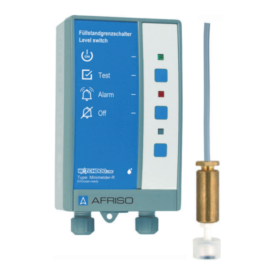
    Anhand der Typbezeichnung auf der Vorderseite des Signalteils lässt sich erkennen, ob das Produkt den minimalen oder den maximalen Füllstand überwacht. • Das Produkt Minimelder-R überwacht den minimalen Füllstand in Behäl- tern. • Das Produkt Maximelder-R überwacht den maximalen Füllstand in Behäl- tern.
  • Seite 9 (Wechsler) zur Verfügung. A. Bezeichnung des Pro- dukts B. Grüne LED C. Test-Taste D. Rote LED E. Quittiertaste F. Ohne Funktion G. LRN-Taste H. Icon aus der AFRISO- home App I. Typbezeichnung des Pro- dukts Abbildung 2: Signalteil Minimelder-R / Maximelder-R...
  • Seite 10 Taste Mit der Test-Taste wird die Funktionsprüfung des Pro- dukts durchgeführt. Anzeige Die rote LED rechts neben dem Symbol signalisiert, dass eine Störung oder ein Alarm vorliegt. Taste Mit dieser Taste wird der akustische Alarm quit- tiert/abgeschaltet. Minimelder-R / Maximelder-R...
  • Seite 11 Produktbeschreibung Abmessungen 65 mm 100 mm 60 mm Minimelder-R / Maximelder-R...
  • Seite 12: Anwendungsbeispiele

    Produktbeschreibung Anwendungsbeispiel(e) Abbildung 3: Standardanwendung Minimelder-R Abbildung 4: Standardanwendung Maximelder-R Minimelder-R / Maximelder-R...
  • Seite 13 Produktbeschreibung Funktion 4.4.1 Minimelder-R Der Minimelder-R überwacht das Absinken des Flüssigkeitspegels. Wenn der Alarm-Schaltpunkt erreicht ist, leuchtet die rote LED dauerhaft und der akustische Alarm ertönt. 4.4.2 Maximelder-R Der Maximelder-R überwacht das Ansteigen des Flüssigkeitspegels. Wenn der Alarm-Schaltpunkt erreicht ist, leuchtet die rote LED dauerhaft und der akustische Alarm ertönt.
  • Seite 14: Zulassungsdokumente, Bescheinigungen, Erklärungen

    -5 ... 50 °C Umgebungstemperatur Lagerung -10 ... 60 °C Elektrische Daten Versorgungsspannung AC 230 V ±10 %, 50/60 Hz Nennleistung 5 VA Netzsicherung T 100 mA H (1,5 kA) Schutzklasse (EN 60730) Schutzart (EN 60529) IP 30 Minimelder-R / Maximelder-R...
  • Seite 15 0,35 kg Werkstoff Sondenkörper Polypropylen Sondengewicht Messing Beständigkeit Wasser, Öl Umgebungsbedingungen Umgebungstemperatur Betrieb -5 ... 50 °C Umgebungstemperatur Lagerung -5 ... 55 °C Elektrische Daten Anschlusskabel: Ölflex 2 x 0,5 mm² Standardlänge Maximale Länge 50 m (geschirmt) Minimelder-R / Maximelder-R...
  • Seite 16: Montage

     Stellen Sie sicher, dass die zulässige Umgebungstemperatur am Signal- teil eingehalten wird.  Stellen Sie sicher, dass das Signalteil jederzeit zugänglich und einsehbar ist.  Stellen Sie sicher, dass das Signalteil vor Wasser und Spritzwasser geschützt ist. Minimelder-R / Maximelder-R...
  • Seite 17 Gehäuse als Bohr- schablone. Variante A 1. Befestigen Sie die Schraube an der Wand. 2. Hängen Sie das Signalteil ein. 3. Befestigen Sie das Signal- teil an der Wand mit einer Schraube an der unteren Lasche. Minimelder-R / Maximelder-R...
  • Seite 18 Ø 5 mm durch das Unterteil. 2. Befestigen Sie das Signal- teil an der Wand mit den beiliegenden Schrauben. 3. Schließen Sie das Signal- teil an wie in Kapitel "Elek- trischer Anschluss" beschrieben. 4. Schließen Sie das Signal- teil. Minimelder-R / Maximelder-R...
  • Seite 19 Stellen Sie sicher, dass durch elektrisch leitfähige Gegenstände oder Medien keine Gefährdungen ausgehen können. Nichtbeachtung dieser Anweisungen führt zu Tod oder schweren Verlet- zungen. HINWEIS ELEKTROSTATISCHE ENTLADUNG • Erden Sie sich immer, bevor Sie die elektronischen Bauteile berühren. Nichtbeachtung dieser Anweisungen kann zu Sachschäden führen. Minimelder-R / Maximelder-R...
  • Seite 20: Spannungsversorgung Signalteil

    Klemme N an. - Der Schutzleiter muss nicht angeschlossen werden. 1. Netzsicherung F1 2. Relaissicherung F2 3. Spannungsversorgung 4. Relais für zusätzliche Geräte 5. Schwimmersonde 6. Steckplatz für das EnO- cean®-Funkmodul J1 Steckbrücke (Jumper) Abbildung 5: Elektrischer Anschluss Minimelder-R / Maximelder-R...
  • Seite 21 Stellen Sie sicher, dass die Netzspannung unterbrochen und gegen Wiedereinschalten gesichert ist. 1. Öffnen Sie das Signalteil. 2. Stecken Sie die Steckbrücke (Jumper) auf die Kontakte für die einzu- stellende Betriebsart. A. Öko B. FailSafe Abbildung 6: Betriebsart festlegen 3. Schließen Sie das Signalteil. Minimelder-R / Maximelder-R...
  • Seite 22 Spannungsspitzen beim Abschalten induktiver Verbraucher können negative Auswirkungen auf elektrische Anlagen haben und zur Zerstörung des Schalt- kontakts führen. • Beschalten Sie induktive Verbraucher mit handelsüblichen RC-Kombinatio- nen, beispielsweise 0,1 μF/100 Ohm. Nichtbeachtung dieser Anweisungen kann zu Sachschäden führen. Minimelder-R / Maximelder-R...
  • Seite 23 Nichtbeachtung dieser Anweisungen kann zu Sachschäden führen. Stellen Sie sicher, dass die Netzspannung unterbrochen und gegen Wiedereinschalten gesichert ist. 1. Öffnen Sie das Signalteil. A. Steckplatz für das EnO- C. Gehäuseaussparung (zur Befesti- cean®-Funkmodul gung der Antenne) B. Position Antenne Minimelder-R / Maximelder-R...
  • Seite 24 Gehäusewand) posi- tioniert sein. - Alle Pins müssen in die Buchsenleiste gesteckt sein. 3. Drücken Sie die Antenne des EnOcean®-Funkmo- duls in die drei Gehäuse- aussparungen am Signal- teil ein. 4. Schließen Sie den Deckel des Signalteils wieder. Minimelder-R / Maximelder-R...
  • Seite 25  Stellen Sie sicher, dass das AFRISOhome Gateway sich im „Ein- lern-Modus“ befindet. 1. Drücken Sie die untere Taste (A) einmal kurz. - Das Produkt sendet ein Lern-Telegramm (LRN-TEL). - Das Produkt ist mit dem AFRISOhome Gateway verbunden. Minimelder-R / Maximelder-R...
  • Seite 26: Funktionsprüfung Durchführen

    Inbetriebnahme Funktionsprüfung durchführen 1. Schieben Sie beim Minimelder-R den Schwimmerschalter der Schwim- mersonde nach unten (Minimum-Alarm). - Die rote LED leuchtet und der akustische Alarm ertönt. 2. Schieben Sie beim Maximelder-R den Schwimmerschalter der Schwim- mersonde nach oben (Maximum-Alarm). - Die rote LED leuchtet und der akustische Alarm ertönt.
  • Seite 27: Betrieb

    Bei Spannungsausfall Bei Ausfall der Spannungsversorgung wird kein Alarm ausgelöst. Bei Wie- derkehr der Spannungsversorgung ist das Produkt sofort betriebsbereit. Wenn inzwischen der Minimalfüllstand oder der Maximalfüllstand erreicht wurden, gibt das Produkt nach Wiederkehr der Spannungsversorgung Alarm. Minimelder-R / Maximelder-R...
  • Seite 28: Wartungsintervalle

    3. Setzen Sie eine neue Netzsicherung F1 ein. 4. Stecken Sie die transparente Abdeckhaube wieder auf. 5. Verbinden Sie die Flachbandleitung mit der Steckerleiste. 6. Schließen Sie das Signalteil, siehe auch Punkt 1. 7. Schalten Sie die Netzspannung ein. Minimelder-R / Maximelder-R...
  • Seite 29: Einsatz In Hochwassergefährdeten Gebieten

    5. Verbinden Sie die Flachbandleitung mit der Steckerleiste. 6. Schließen Sie das Signalteil, siehe auch Punkt 1. 7. Schalten Sie die Netzspannung ein. Einsatz in hochwassergefährdeten Gebieten Die Schwimmersonde ist geeignet für hochwassergefährdete Gebiete und ist druckwasserdicht bis 10 mH O (1 bar Außendruck). Minimelder-R / Maximelder-R...
  • Seite 30: Störungsbeseitigung

    Schwimmersonde mersonde Alarm ansteht. Leitungsunterbre- Prüfen Sie das Sonden- chung des Sondenka- kabel bels Drücken der Prüftaste Signalteil defekt Tauschen Sie das Sig- bleibt ohne Wirkung nalteil Sonstige Störungen Bitte wenden Sie sich an die AFRISO-Service Hotline Minimelder-R / Maximelder-R...
  • Seite 31: Außerbetriebnahme Und Entsorgung

    3. Entsorgen Sie das Produkt. Rücksendung Vor einer Rücksendung Ihres Produkts müssen Sie sich mit uns in Verbin- dung setzen (service@afriso.de). Gewährleistung Informationen zur Gewährleistung finden Sie in unseren Allgemeinen Geschäftsbedingungen im Internet unter www.afriso.com oder in Ihrem Kauf- vertrag. Minimelder-R / Maximelder-R...
  • Seite 32: Ersatzteile Und Zubehör

    UNGEEIGNETE TEILE • Verwenden Sie nur Original Ersatz- und Zubehörteile des Herstellers. Nichtbeachtung dieser Anweisung kann zu Sachschäden führen. Produkt Artikelbezeichnung Art.-Nr. Abbildung Minimelder-R (mit Relais) mit Schwimmer- 16701 sonde Maximelder-R (mit Relais) mit Schwim- 16702 mersonde Ersatzteile und Zubehör Artikelbezeichnung Art.-Nr.
  • Seite 33 EnOcean®-Funksystemen finden Sie auf www.enocean.com. • Funkstandard • Funktechnologie • AN001 • AN102 • AN103 • AN201 14.3 Möglichkeiten der EnOcean®-Technologie Unterlagen über EnOcean®-Technologien finden Sie im Internet unter www.afrisohome.de. Auf unserem YouTube-Channel finden Sie eine Reihe von Videos zu AFRISO-Produkten. Minimelder-R / Maximelder-R...
  • Seite 34 Anhang Anhang 15.1 EU-Konformitätserklärung Minimelder-R / Maximelder-R...
  • Seite 35 Operating  instructions Level switches Minimelder-R Maximelder-R with relay Copyright 2020 AFRISO-EURO-INDEX GmbH. All rights reserved. Lindenstraße 20 74363 Güglingen Telephone +49 7135 102-0 Service +49 7135 102-211 Telefax +49 7135 102-147 info@afriso.com Version: 03.2020.0 www.afriso.com ID: 900.000.0206...
  • Seite 36 About these operating instructions About these operating instructions These operating instructions describe the level switches Minimelder-R and Maximelder-R (also referred to as "product" in these operating instructions). These operating instructions are part of the product. • You may only use the product if you have fully read and understood these operating instructions.
  • Seite 37: Information On Safety

    This symbol alerts to hazardous electrical voltage. If this symbol is used in a safety message, there is a hazard of electric shock. Minimelder-R / Maximelder-R...
  • Seite 38: Intended Use

    Minimelder-R / Maximelder-R...
  • Seite 39 Modifications to the product Only perform work on and with the product which is explicitly described in these operating instructions. Do not make any modifications to the product which are not described in these operating instructions. Minimelder-R / Maximelder-R...
  • Seite 40: Transport And Storage

    Use the original packaging when transporting the product. • Store the product in a clean and dry environment. • Verify that the product is protected against shocks and impact during trans- port and storage. Failure to follow these instructions can result in equipment damage. Minimelder-R / Maximelder-R...
  • Seite 41: Product Description

    • The product Minimelder-R monitors the minimum level in tanks. • The product Minimelder-R monitors the maximum level in tanks.
  • Seite 42 A. Designation of product B. Green LED C. Test key D. Red LED E. Acknowledge button F. Without function G. LRN pushbutton H. Icon from AFRISOhome I. Type designation of the product Fig 2: Control unit Minimelder-R / Maximelder-R...
  • Seite 43 The Test key allows you to perform the function test of the product. Indicator The red LED to the right of the symbol indicates an alarm or an error. This key allows you to acknowledge and mute the audible alarm. Minimelder-R / Maximelder-R...
  • Seite 44 Product description Dimensions 65 mm 100 mm 60 mm Minimelder-R / Maximelder-R...
  • Seite 45: Application Examples

    Product description Application example(s) Fig 3: Standard application Minimelder-R Fig 4: Standard application Maximelder-R Minimelder-R / Maximelder-R...
  • Seite 46 Product description Function 4.4.1 Minimelder-R Minimelder-R monitors a falling level of the liquid. When the alarm switch- ing point is reached, the red LED lights solid and the audible alarm sounds. 4.4.2 Maximelder-R Maximelder-R monitors a rising level of the liquid. When the alarm switch- ing point is reached, the red LED lights solid and the audible alarm sounds.
  • Seite 47: Control Unit

    -10 ... 60 °C Electrical data Supply voltage AC 230 V ±10 %, 50/60 Hz Nominal power 5 VA Mains fuse T 100 mA H (1.5 kA) Protection class (EN 60730) Degree of protection (EN 60529) IP 30 Minimelder-R / Maximelder-R...
  • Seite 48 Probe weight Brass Resistance Water, oil Ambient conditions Ambient temperature operation -5 ... 50 °C Ambient temperature storage -5 ... 55 °C Electrical data Ölflex 2 x 0.5 mm² Connection cable: Standard length Maximum length 50 m (shielded) Minimelder-R / Maximelder-R...
  • Seite 49 The height at which the float switch of the floating probe is mounted corre- sponds to the alarm switching point.  Verify that the correct floating probe for Minimelder-R or Maximelder-R is mounted (fee figure “Floating probe” on page 7).
  • Seite 50 A or B. Use the housing as a drilling template. Mounting type A 1. Mount the screw to the wall. 2. Fit the control unit. 3. Fasten the control unit by screwing the bottom lug to the wall. Minimelder-R / Maximelder-R...
  • Seite 51 1. Drill two fixing holes with a Ø 5 mm into the base. 2. Mount the control unit to the wall with the enclosed screws. 3. Connect the control unit as described in chapter "Electrical connection". 4. Close the control unit. Minimelder-R / Maximelder-R...
  • Seite 52 • Do not install mains plugs or switches in the supply line to the product. • Only power on/power off the product via the on-site mains fuse. Failure to follow these instructions can result in equipment damage. Minimelder-R / Maximelder-R...
  • Seite 53 5.3.2 Connecting the floating probe 1. Install the probe cable. 2. Route the probe cable through the cable gland at the right to the termi- nals designated "Sonde". 3. Connect the two wires. Any polarity is permissible. Minimelder-R / Maximelder-R...
  • Seite 54 Verify that the mains voltage is interrupted and cannot be switched on. 1. Open the control unit. 2. Plug the jumper onto the contacts for the operating mode to be set. A. Eco B. Failsafe Fig 6: Setting the operating mode 3. Close the control unit. Minimelder-R / Maximelder-R...
  • Seite 55 • Use commercially available standard RC combinations such as 0.1 μF/100 Ohm for inductive consumers. Failure to follow these instructions can result in equipment damage. Minimelder-R / Maximelder-R...
  • Seite 56 Failure to follow these instructions can result in equipment damage. Verify that the mains voltage is interrupted and cannot be switched on. 1. Open the control unit. A. Slot for EnOcean® wireless C. Housing opening (for fastening module the antenna) B. Position antenna Minimelder-R / Maximelder-R...
  • Seite 57 - All pins must be inserted into the female connec- tor. 3. Push the antenna of the EnOcean® wireless module into the three hou- sing openings of the cont- rol unit. 4. Close the cover of the control unit. Minimelder-R / Maximelder-R...
  • Seite 58  Verify that the AFRISOhome gateway is in "Learn" mode. 1. Briefly press the lower key (A) once. - The product sends a Learn telegram (LRN-TEL). - The product is now con- nected to the AFRISO- home gateway. Minimelder-R / Maximelder-R...
  • Seite 59 Commissioning Performing the function test 1. Minimelder-R: Push the float switch of the floating probe down (minimum alarm). - The red LED lights up and the audible alarm sounds. 2. Maximelder-R: Push the float switch of the floating probe up (maximum alarm).
  • Seite 60: Operation

    The alarm remains active until the level is below the maximum level (Maximelder-R) or above the min- imum level (Minimelder-R). Power outage No alarm is triggered in case of a power outage. When mains voltage is restored, the product immediately resumes operation.
  • Seite 61: Maintenance Activities

    2. Remove the transparent cover from the mains fuse F1. See "Electrical connection" on page 19. 3. Insert a new mains fuse F1. 4. Refit the transparent cover. 5. Connect the flat cable to the connector. 6. Close the control unit, see 1 above. 7. Apply mains voltage. Minimelder-R / Maximelder-R...
  • Seite 62 6. Close the control unit, see 1 above. 7. Apply mains voltage. Use in flood hazard areas The floating probe is suitable for use in flood hazard areas; it is watertight up to 10 mH O (1 bar pressure). Minimelder-R / Maximelder-R...
  • Seite 63: Troubleshooting

    Line interruption in the Check the probe cable probe cable Pressing the Test but- Control unit defective Replace the control unit ton has no effect Other malfunctions Contact the AFRISO service hotline Minimelder-R / Maximelder-R...
  • Seite 64: Decommissioning / Disposal

    3. Dispose of the product. Returning the device Get in touch with us before returning your product (service@afriso.de). Warranty See our terms and conditions at www.afriso.com or your purchase contract for information on warranty. Minimelder-R / Maximelder-R...
  • Seite 65: Spare Parts And Accessories

    Only use genuine spare parts and accessories provided by the manufac- turer. Failure to follow these instructions can result in equipment damage. Product Product designation Part no. Figure Minimelder-R (with relay) with floating 16701 probe Maximelder-R (with relay) with floating 16702 probe Spare parts and accessories Product designation Part no.
  • Seite 66 • AN001 • AN102 • AN103 • AN201 14.3 Features of the EnOcean® technology Visit www.afrisohome.de for documents on EnOcean® technologies. A variety of videos on AFRISO products can also be found on the AFRISO YouTube channel. Minimelder-R / Maximelder-R...
  • Seite 67 Appendix Appendix 15.1 EU Declaration of Conformity Minimelder-R / Maximelder-R...
  • Seite 68: Notice Technique

    Notice technique Interrupteur de niveau Minimelder-R Maximelder-R avec relais Copyright 2020 AFRISO-EURO-INDEX GmbH. Tous droits réservés. Lindenstraße 20 74363 Güglingen Téléphone +49 7135 102-0 Service clientèle +49 7135 102-211 Téléfax +49 7135 102-147 info@afriso.com Version: 03.2020.0 www.afriso.com ID: 900.000.0206...
  • Seite 69 La responsabilité du fabricant ou la garantie ne pourra être engagée pour des dommages ou dommages consécutifs résultant d'une inobservation de cette notice technique ou des directives, règlements et normes en vigueur sur le lieu d'installation du produit. Minimelder-R / Maximelder-R...
  • Seite 70: Informations Sur La Sécurité

    Ce pictogramme avertit d'une tension électrique dange- reuse. Si ce pictogramme s'affiche dans une consigne de sécurité, il y a un risque de choc électrique. Minimelder-R / Maximelder-R...
  • Seite 71: Usage Normal

    Pendant l'utilisation du produit effectuez toutes les opérations exclusivement dans les conditions spécifiées dans cette notice technique et sur la plaque signalétique, conformément aux données techniques spécifiées et en accord avec tous les règlements, normes et consignes de sécurité en vigueur sur le lieu d'installation. Minimelder-R / Maximelder-R...
  • Seite 72 Modification du produit En travaillant sur le produit et avec celui-ci, effectuez exclusivement les opé- rations décrites dans cette notice technique. N'effectuez pas de modifica- tions non décrites dans cette notice technique. Minimelder-R / Maximelder-R...
  • Seite 73: Transport Et Stockage

    • Stockez le produit dans un lieu sec et propre. • Assurez-vous que le produit est à l'abri des chocs pendant le transport et le stockage. La non-observation de ces instructions peut causer des dommages maté- riels. Minimelder-R / Maximelder-R...
  • Seite 74: Description Du Produit

    à la face de l'unité de commande indique si le produit sur- veille le niveau minimal ou maximal. • Le produit Minimelder-R surveille le niveau minimal dans un réservoir. • Le produit Maximelder-R surveille le niveau maximum dans un réservoir.
  • Seite 75 A. Désignation du produit B. LED verte C. Touche Test D. LED rouge E. Touche d'acquittement F. Sans fonction G. Touche LRN H. Icône de l'app AFRISO- home I. Désignation de type de produit Figure 2: Unité de commande Minimelder-R / Maximelder-R...
  • Seite 76 à fonctionner. Touche La touche Test permet d'effectuer un test de fonction- nement du produit. Affichage La LED rouge à la droite du symbole indique une alarme/un défaut. Touche Cette touche permet d'acquitter et de couper l'alarme sonore. Minimelder-R / Maximelder-R...
  • Seite 77 Description du produit Dimensions 65 mm 100 mm 60 mm Minimelder-R / Maximelder-R...
  • Seite 78: Exemple(S) D'application

    Description du produit Exemple(s) d'application Figure 3: Utilisation standard Minimelder-R Figure 4: Utilisation standard Maximelder-R Minimelder-R / Maximelder-R...
  • Seite 79 Description du produit Fonctionnement 4.4.1 Minimelder-R Minimelder-R surveille la baisse du niveau de liquide. Si le point de com- mutation d'alarme est atteint, la LED rouge s'allume en continu et l'alarme sonore retentit. 4.4.2 Maximelder-R Maximelder-R surveille la montée du niveau de liquide. Si le point de com- mutation d'alarme est atteint, la LED rouge s'allume en continu et l'alarme sonore retentit.
  • Seite 80: Caractéristiques Techniques

    -10 ... 60 °C Données électriques Tension d'alimentation AC 230 V ±10 %, 50/60 Hz Puissance nominale 5 VA Fusible de secteur T 100 mA H (1,5 kA) Classe de protection (EN 60730) Degré de protection (EN 60529) IP 30 Minimelder-R / Maximelder-R...
  • Seite 81 Résistance Eau, huile Conditions ambiantes Température ambiante service -5 ... 50 °C Température ambiante stockage -5 ... 55 °C Données électriques Câble de branchement : Ölflex 2 x 0,5 mm² Longueur standard Longueur maximale 50 m (blindé) Minimelder-R / Maximelder-R...
  • Seite 82: Montage

    La hauteur à laquelle l'interrupteur à flotteur de la sonde à flotteur est fixé correspond au point de commutation d'alarme.  Assurez-vous que la sonde à flotteur appropriée pour le Minimelder-R ou le Maximelder-R est montée (voir figure "Sonde à flotteur", page 7).
  • Seite 83 Type de fixation A 1. Introduisez la vis dans le mur. 2. Accrochez l'unité de com- mande. 3. Fixez l'unité de com- mande sur la paroi en vis- sant la vis dans la patte inférieure. Minimelder-R / Maximelder-R...
  • Seite 84 Ø 5 mm dans la partie inférieure. 2. Fixez l'unité de com- mande sur le mur avec les vis fournies. 3. Raccordez l'unité de com- mande comme décrit dans le chapitre "Bran- chement électrique". 4. Fermez l'unité de com- mande. Minimelder-R / Maximelder-R...
  • Seite 85 La non-observation de ces instructions entraîne la mort ou des blessures graves. AVIS DÉCHARGES ÉLECTROSTATIQUES • Reliez-vous à la terre avant de toucher des composants susceptibles d'être endommagés par décharge électrostatique. La non-observation de ces instructions peut causer des dommages maté- riels. Minimelder-R / Maximelder-R...
  • Seite 86 - Il n'est pas nécessaire de brancher le conducteur de protection. 1. Fusible de secteur F1 2. Fusible relais F2 3. Alimentation 4. Relais pour équipement supplémentaire 5. Sonde à flotteur 6. Connecteur femelle pour le module sans fil EnO- cean® J1 cavalier Figure 5: Branchement électrique Minimelder-R / Maximelder-R...
  • Seite 87 éviter la remise en marche. 1. Ouvrez l'unité de commande. 2. Placez le cavalier sur les broches pour le mode de fonctionnement à régler. A. Eco B. FailSafe Figure 6: Régler le mode de fonctionnement 3. Fermez l'unité de commande. Minimelder-R / Maximelder-R...
  • Seite 88 électriques et la destruction du contact. • En cas de charges inductives, utilisez un circuit RC de protection (par exemple 0,1 μF/100 Ohm). La non-observation de ces instructions peut causer des dommages maté- riels. Minimelder-R / Maximelder-R...
  • Seite 89 Assurez-vous que la tension secteur soit coupée et prenez toutes les mesures nécessaires pour éviter la remise en marche. 1. Ouvrez l'unité de commande. A. Connecteur femelle pour le C. Trou (pour la fixation de l'antenne) module sans fil EnOcean® B. Position de l'antenne Minimelder-R / Maximelder-R...
  • Seite 90 - Toutes les broches doi- vent se trouver dans le connecteur femelle. 3. Poussez l'antenne du module sans fil EnO- cean® dans les deux trous de l'unité de com- mande. 4. Refermez le couvercle de l'unité de commande. Minimelder-R / Maximelder-R...
  • Seite 91: Mise En Service

     Vérifiez que la passerelle AFRISOhome est en mode "Connexion". 1. Appuyez brièvement une fois sur la touche infé- rieure (A). - Le produit transmet un télégramme de conne- xion (LRN-TEL). - Le produit est connecté à la passerelle AFRISO- home. Minimelder-R / Maximelder-R...
  • Seite 92 Mise en service Effectuer le test de fonctionnement 1. En cas de Minimelder-R, faites déplacer l'interrupteur à flotteur de la sonde à flotteur vers le bas (alarme minimale). - La LED rouge est allumée et l'alarme sonore retentit. 2. En cas de Maximelder-R, faites déplacer l'interrupteur à flotteur de la sonde à...
  • Seite 93 Appuyez une nouvelle fois sur la touche pour remettre en marche l'alarme sonore. L'alarme reste active jusqu'à ce que le niveau soit inférieur au niveau maximum (Maximelder-R) ou supérieur au niveau minimum (Minimelder-R). En cas de panne secteur En cas de panne secteur, il n'y a pas de déclenchement d'alarme. Le produit est immédiatement remis en marche dès qu'il est de nouveau sous tension.
  • Seite 94: Intervalles De Maintenance

    Voir "Branchement électrique", page 19. 3. Installez un nouveau fusible de secteur F1. 4. Remontez le capot de protection transparent. 5. Branchez le câble plat au connecteur. 6. Fermez l'unité de commande, voir aussi point 1. 7. Allumez la tension secteur. Minimelder-R / Maximelder-R...
  • Seite 95 6. Fermez l'unité de commande, voir aussi point 1. 7. Allumez la tension secteur. Utilisation dans zones à risque d'inondation La sonde à flotteur est appropriée à l'utilisation dans des zones à risque d'inondation et étanche à l'eau jusqu'à 10 mH O (1 bar pression). Minimelder-R / Maximelder-R...
  • Seite 96: Suppression Des Dérangements

    Câble de sonde inter- Vérifiez le câble de rompu sonde L'actionnement de la Unité de commande Remplacez l'unité de touche de test reste défectueuse commande sans effet Autre dérangement Veuillez contacter l'AFRISO Service  Hotline Minimelder-R / Maximelder-R...
  • Seite 97: Mise Hors Service Et Élimination

    Avant de retourner le produit, il faut que vous preniez contact avec nous  (service@afriso.de). Garantie Les informations sur la garantie figurent dans nos "Conditions générales de vente" sur le site www.afriso.com ou dans votre contrat d'achat. Minimelder-R / Maximelder-R...
  • Seite 98: Pièces Détachées Et Accessoires

    N'utilisez que des accessoires et des pièces détachées d'origine provenant du fabricant. La non-observation de ces instructions peut causer des dommages maté- riels. Produit Désignation de l'article Référence Figure Minimelder-R (avec relais) avec sonde à 16701 flotteur Maximelder-R (avec relais) avec sonde à 16702 flotteur Pièces détachées et accessoires Désignation de l'article...
  • Seite 99 • AN102 • AN103 • AN201 14.3 Possibilités de la technologie EnOcean® Vous trouverez des documents supplémentaires sur les technologies EnO- cean® sur www.afrisohome.de. Visitez le canal YouTube d'AFRISO et découvrez des vidéos sur les produits AFRISO. Minimelder-R / Maximelder-R...
  • Seite 100 Annexe Annexe 15.1 Déclaration de conformité UE Minimelder-R / Maximelder-R...
  • Seite 101: Istruzioni Per L'uso

    Istruzioni per l’uso Interruttori di livello Minimelder-R Maximelder-R con relè Copyright 2020 AFRISO-EURO-INDEX GmbH. Tutti i diritti sono riservati. Lindenstraße 20 74363 Güglingen Telefono +49 7135 102-0 Servizio di assistenza +49 7135 102-211 Telefax +49 7135 102-147 info@afriso.com Versione: 03.2020.0...
  • Seite 102: Su Queste Istruzioni Per L'uso

    Su queste Istruzioni per l'uso Su queste Istruzioni per l'uso Queste Istruzioni per l'uso descrivono gli interruttori di livello Minimelder-R e Maximelder-R (nel proseguio anche "prodotto"). Le presenti Istruzioni per lʼuso costituiscono parte del prodotto. • L'utilizzo del prodotto è permesso soltanto dopo aver letto e capito com- pletamente le Istruzioni per l'uso.
  • Seite 103 Questo simbolo segnala tensione elettrica pericolosa. Quando questo simbolo è riportato all'interno un avverti- mento segnala pericolo da scossa elettrica. Minimelder-R / Maximelder-R...
  • Seite 104: Informazioni Sulla Sicurezza

    Quando utilizzate il prodotto, eseguite tutti i lavori esclusivamente nel rispetto delle condizioni specificate nelle Istruzioni per l'uso e sulla targhetta conosci- tiva, nell'ambito dei dati tecnici specificati e in osservanza di tutte le disposi- zioni norme e prescrizioni di sicurezza vigenti sul luogo d'impiego. Minimelder-R / Maximelder-R...
  • Seite 105: Uso Improprio Prevedibile

    Modifiche del prodotto Eseguite esclusivamente i lavori con e al prodotto descritti nelle Istruzioni per l'uso. Non apportate modifiche al prodotto che non sono descritte nelle Istru- zioni per l'uso. Minimelder-R / Maximelder-R...
  • Seite 106: Trasporto E Magazzinaggio

    Per il trasporto, utilizzate l'imballaggio originale. • Immagazzinate il prodotto solo in ambiente asciutto e pulito. • Assicurare che il prodotto sia prodotto contro urti durante il trasporto e il magazzinaggio. La mancata osservanza di queste indicazioni può causare danni materiali. Minimelder-R / Maximelder-R...
  • Seite 107 Dalla targhetta conoscitiva sul fronte dell'unità di segnale si riconosce se il prodotto sorveglia il livello minimo o massimo. • Il prodotto Minimelder-R sorveglia il livello minimo di un serbatoio. • Il prodotto Maximelder-R sorveglia il livello massimo di un serbatoio.
  • Seite 108: Descrizione Del Prodotto

    A. Nome del prodotto B. LED verde C. Pulsante di test D. LED rosso E. Tasto di tacitazione allarme F. Senza funzione G. Pulsante LRN H. Icona AFRISOhome app I. Nome di tipo del prodotto Figura 2: Unità di segnale Minimelder-R / Maximelder-R...
  • Seite 109 Il pulsante di prova permette di eseguire la prova di funzionamento del prodotto. Visualizzazione In caso di allarme, la spia rossa accanto al simbolo segnala la presenza di un disturbo/allarme. Pulsante Con questo pulsante si tacita/disinserisce l'allarme acustico. Minimelder-R / Maximelder-R...
  • Seite 110 Descrizione del prodotto Dimensioni 65 mm 100 mm 60 mm Minimelder-R / Maximelder-R...
  • Seite 111: Esempio Applicativo

    Descrizione del prodotto Esempio applicativo Figura 3: Applicazione standard Minimelder-R Figura 4: Applicazione standard Maximelder-R Minimelder-R / Maximelder-R...
  • Seite 112 Descrizione del prodotto Funzionamento 4.4.1 Minimelder-R Il Minimelder-R sorveglia il calo del livello sotto la soglia impostata. Quando la soglia di allarme è raggiunta, il LED rosso si accende e si sente l'allarme acustico. 4.4.2 Maximelder-R Il Maximelder-R sorveglia l'aumento del livello di liquido. Quando la soglia di allarme è...
  • Seite 113 1 relè dʼuscita (scambiatore) Potere di rottura relè dʼuscita max. 250 V, 2 A, carico resist. ohmico Fusibile relè T 2 A Condizioni ambiente Temperatura ambiente - Funziona- -5 ... 50 °C mento Temperatura ambiente magazzinaggio -10 ... 60 °C Minimelder-R / Maximelder-R...
  • Seite 114 Condizioni ambiente Temperatura ambiente - Funziona- -5 ... 50 °C mento Temperatura ambiente magazzinaggio -5 ... 55 °C Dati elettrici Cavo di collegamento Ölflex 2 x 0,5 mm² Lunghezza standard Lunghezza massima 50 m (schermati) Minimelder-R / Maximelder-R...
  • Seite 115  Verificate che presso l'unità di segnale sia rispettata la temperatura ambiente ammessa.  Assicurare che l'unità di segnale sia facilmente accessibile e visibile in ogni momento.  Assicurare che l'unità di segnale sia protetta contro acqua e spruzzi. Minimelder-R / Maximelder-R...
  • Seite 116 (utilizzare la variante A o B) Utilizzare l'alloggiamento come dima di foratura. Variante A 1. Fissate la vite al muro. 2. Appendere l'unità di segnale. 3. Fissare al muro l'unità di segnale con una vite nella linguetta inferiore. Minimelder-R / Maximelder-R...
  • Seite 117 1. Praticare due fori di fis- saggio Ø 5 mm nella parte inferiore. 2. Montare l'unità di segnale a parete con le viti a cor- redo. 3. Allacciare l'unità di segnale come descritto al Capitolo "Allacciamento elettrico". 4. Chiudere lʼunità di segnale. Minimelder-R / Maximelder-R...
  • Seite 118 Non installare spine di rete o interruttori lungo l'allacciamento fisso del pro- dotto. • Inserire il prodotto solo mediante la protezione di rete a cura del committente. La mancata osservanza di queste indicazioni può causare danni materiali. Minimelder-R / Maximelder-R...
  • Seite 119 Collegare sonda la galleggiante 1. Posare il cavo della sonda. 2. Inserire il cavo della sonda attraverso il passacavo destro e condurlo al morsetto con la dicitura "Sonde". 3. Collegare i due fili. La polarità è a piacere. Minimelder-R / Maximelder-R...
  • Seite 120 Assicurate che la tensione di rete sia interrotta e protetta contro il rein- serimento. 1. Aprire l'unità di segnale. 2. Inserire il ponticello (jumper) sui contatti per la modalità di esercizio selezionata. A. Öko B. FailSafe Figura 6: Determinare la modalità di esercizio 3. Chiudere lʼunità di segnale. Minimelder-R / Maximelder-R...
  • Seite 121: Uscita Relè

    • Collegare le utenze induttive con le comuni combinazioni RC, ad es. 0,1 μF/100 Ohm. La mancata osservanza di queste indicazioni può causare danni materiali. Minimelder-R / Maximelder-R...
  • Seite 122 Assicurate che la tensione di rete sia interrotta e protetta contro il rein- serimento. 1. Aprire l'unità di segnale. A. Slot per il modulo radio EnO- C. Incavo nellʼinvolucro (per fissare ® cean lʼantenna) B. Posizione antenna Minimelder-R / Maximelder-R...
  • Seite 123 (vicino al lato dellʼinvolucro); - tutti i piedini devono incastrare nel connet- tore; 3. inserire premendo lʼantenna del modulo radio EnOcean® nei tre incavi dellʼinvolucro dellʼunità di segnale; 4. richiudere il coperchio dell'unità di segnale. Minimelder-R / Maximelder-R...
  • Seite 124: Messa In Funzione Del Prodotto

     Assicurare che il gateway AFRISOhome si trovi in "modalità di apprendi- mento". 1. Premere brevemente il tasto inferiore (A). - Il prodotto trasmette un telegramma di apprendi- mento (LRN-TEL). - Il prodotto ha stabilito la connessione al gateway AFRISOhome. Minimelder-R / Maximelder-R...
  • Seite 125: Prova Di Funzionamento

    Messa in funzione Prova di funzionamento 1. Per Minimelder-R, spingere verso il basso (allarme di minimo) l'interrut- tore della sonda galleggiante. - Il LED rosso si accende e si sente lʼallarme acustico. 2. Per Maximelder-R, spingere verso l'alto (allarme di massimo) l'interruttore della sonda galleggiante.
  • Seite 126: Operazione

    In caso di caduta della tensione di rete non viene dato allarme. Al ritorno della tensione di rete, lʼapparecchio è immediatamente pronto al funzionamento. Se nel frattempo è stato raggiunto il livello limite minimo o massimo, il pro- dotto fa scattare l'allarme quando torna la tensione di rete. Minimelder-R / Maximelder-R...
  • Seite 127: Interventi Di Manutenzione

    3. Inserire un nuovo fusibile F 1. 4. Rimontare il coperchio trasparente sul fusibile. 5. Collegare la piattina multipolare al listello di connessione. 6. Richiudere lʼunità di segnale, vedere anche al punto 1. 7. Inserire la tensione di rete. Minimelder-R / Maximelder-R...
  • Seite 128 7. Inserire la tensione di rete. Impiego in zone a rischio d’inondazione La sonda galleggiante è idonea all'impiego in zone a rischio di inondazione o alluvione e resiste a pressioni idriche fino a 10 mH2O(1 bar pressione esterna). Minimelder-R / Maximelder-R...
  • Seite 129: Riparazione Guasti

    Interruzione della linea Controllare il cavo della allarme. del cavo sonda sonda Il pulsante di prova non Unità di segnale difet- Sostituire l'unità di tosa segnale funziona (non ha effetto) Altri guasti Rivolgetevi alla hotline di assistenza AFRISO Minimelder-R / Maximelder-R...
  • Seite 130: Smontaggio E Smaltimento

    Rispedizione al fornitore Prima di rispedire il prodotto, mettetevi in contatto con noi. (ser- vice@afriso.de). Garanzia Le informazioni sulla garanzia sono riportate nelle condizioni di contratto generali in internet sul sito www.afriso.com o nel vostro contratto d'acquisto. Minimelder-R / Maximelder-R...
  • Seite 131: Ricambi E Accessori

    Utilizzare solo pezzi di ricambio e accessori del produttore. La mancata osservanza di queste indicazioni può causare danni materiali. Prodotto Nome articolo Art. N° Figura Minimelder-R (con relè) con sonda galleg- 16701 giante Maximelder-R (con relè) con sonda galleg- 16702 giante...
  • Seite 132 Tecnologia radio • AN001 • AN102 • AN103 • AN201 14.3 I vantaggi della tecnologia EnOcean® Documenti sulle tecnologie EnOcean® sono richiamabili dal sito internet www.afrisohome.de. Video su prodotti AFRISO si trovano anche sul canale YouTube AFRISO. Minimelder-R / Maximelder-R...
  • Seite 133 Appendice Appendice 15.1 Dichiarazione di conformità UE Minimelder-R / Maximelder-R...
  • Seite 134 Appendice Minimelder-R / Maximelder-R...
  • Seite 135: Instrukcja  Eksploatacji

    Instrukcja  eksploatacji Sygnalizator graniczny poziomu napełnienia Minimelder-R Maximelder-R z przekaźnikiem Copyright 2012 AFRISO-EURO-INDEX GmbH. Wszystkie prawa zastrzeżone. Lindenstraße 20 74363 Güglingen Telefon +49 7135 102-0 Obsługa klienta +49 7135 102-211 Telefaks +49 7135 102-147 info@afriso.com www.afriso.com Version: 03.2020.0 ID: 900.000.0206...
  • Seite 136 Objaśnienia do niniejszej instrukcji eksploatacji Objaśnienia do niniejszej instrukcji eksploatacji Niniejsza instrukcja eksploatacji opisuje sygnalizatory graniczne poziomu napełnienia Minimelder-R oraz Maximelder-R (poniżej zwane także „produk- tem“). Niniejsza instrukcja eksploatacji jest częścią produktu. • Produkt wolno użytkować dopiero po całkowitym przeczytaniu i pełnym zro- zumieniu instrukcji eksploatacji.
  • Seite 137: Informacje Na Temat Bezpieczeństwa

    To jest ogólny symbol ostrzegawczy. Wskazuje on na wystę- powanie niebezpieczeństwa obrażeń oraz szkód material- nych. Należy przestrzegać wszystkich wskazówek opisanych w powiązaniu z tym symbolem ostrzegawczym w celu unik- nięcia wypadków ze skutkiem śmiertelnym, obrażeń oraz szkód materialnych. Minimelder-R / Maximelder-R...
  • Seite 138 Należy też przy tym uwzględnić możliwe konsekwencje wynikające z zabudowy lub integracji produktu w systemie lub instalacji. Minimelder-R / Maximelder-R...
  • Seite 139 źródłem nie jest bezpośrednio sam produkt. Modyfikacje produktu Przy produkcie oraz z jego pomocą należy wykonywać wyłącznie takie czynno- ści, które są opisane w niniejszej instrukcji eksploatacji. Nie wolno wprowadzać zmian, które nie są opisane w niniejszej instrukcji eksploatacji. Minimelder-R / Maximelder-R...
  • Seite 140: Transport I Składowanie

    • Do celów transportowych należy wykorzystywać oryginalne opakowanie. • Produkt należy przechowywać wyłącznie w suchym i czystym otoczeniu. • Należy upewnić się, że podczas transportu i składowania produkt jest chro- niony przed uderzeniami. Nieprzestrzeganie niniejszych zaleceń może doprowadzić do powstania szkód materialnych. Minimelder-R / Maximelder-R...
  • Seite 141: Opis Produktu

    Produkt składa się z sygnalizatora oraz sondy pływakowej. Na podstawie ozna- czenia typu umieszczonego na przedniej stronie sygnalizatora można stwier- dzić, czy produkt monitoruje minimalny czy maksymalny poziom napełnienia. • Produkt Minimelder-R monitoruje minimalny poziom napełnienia zbiorników. • Produkt Maximelder-R monitoruje maksymalny poziom napełnienia zbiorni- ków.
  • Seite 142 A. oznaczenie produktu B. zielona dioda LED C. przycisk testu D. czerwona dioda LED E. przycisk odstawienia F. bez funkcji G. przycisk LRN H. ikona z aplikacji AFRISO- home App I. oznaczenie typu produktu Ilustracja 2: Sygnalizator Minimelder-R / Maximelder-R...
  • Seite 143 Po włączeniu produktu zielona dioda LED po prawej stronie symbolu sygnalizuje gotowość do eksploatacji. Przycisk Przycisk testu umożliwia sprawdzenie działania pro- duktu. Wskaźnik Czerwona dioda LED po prawej stronie symbolu sygna- lizuje wystąpienie zakłócenia lub alarmu. Przycisk Ten przycisk umożliwia potwierdzenie/wyłączenie alarmu akustycznego. Minimelder-R / Maximelder-R...
  • Seite 144 Opis produktu Wymiary 65 mm 100 mm 60 mm Minimelder-R / Maximelder-R...
  • Seite 145 Opis produktu Przykład(y) zastosowania Ilustracja 3: Zastosowanie standardowe Minimelder-R Ilustracja 4: Zastosowanie standardowe Maximelder-R Minimelder-R / Maximelder-R...
  • Seite 146 Opis produktu Działanie 4.4.1 Minimelder-R Minimelder-R monitoruje spadek poziomu cieczy. Po osiągnięciu punktu włączenia alarmu czerwona dioda LED świeci się światłem ciągłym i rozlega się alarm akustyczny. 4.4.2 Maximelder-R Maximelder-R monitoruje wzrost poziomu cieczy. Po osiągnięciu punktu włączenia alarmu czerwona dioda LED świeci się światłem ciągłym i rozlega się...
  • Seite 147 T 2 A Warunki otoczenia temperatura otoczenia podczas pracy -5 ... 50 °C temperatura otoczenia podczas maga- -10 ... 60 °C zynowania napięcia zasilania AC 230 V ± 10 %, 50 ... 60 Hz Minimelder-R / Maximelder-R...
  • Seite 148 Warunki otoczenia temperatura otoczenia podczas pracy -5 ... 50 °C temperatura otoczenia podczas maga- -5 ... 55 °C zynowania Dane elektryczne przewód przyłączeniowy: Ölflex 2 x 0,5 mm² długość standardowa długość maksymalna 50 m (w wersji ekranowanej) Minimelder-R / Maximelder-R...
  • Seite 149  Należy upewnić się, że zamontowana została sonda pływakowa pasująca do układu Minimelder-R lub Maximelder-R (patrz ilustracja “Sonda pływa- kowa” na stronie 7). 1. Spuścić do zbiornika sondę pływakową zawieszoną na przewodzie.
  • Seite 150 2. Zamontować korpus na ścianie (zastosować wariant A lub B). Korpus wykorzystać jako szablon do wykonania otworów. Wariant A 1. Zamocować śrubę w ścia- nie. 2. Zawiesić sygnalizator. 3. Przymocować sygnalizator do ściany śrubą przy wykorzystaniu dolnej wypustki. Minimelder-R / Maximelder-R...
  • Seite 151 Wariant B 1. Przewiercić dwa otwory montażowe Ø 5 mm w dolnej części. 2. Przymocować sygnalizator do ściany przy pomocy dołączonych śrub. 3. Podłączyć sygnalizator w sposób opisany w roz- dziale "Przyłącze elek- tryczne". 4. Zamknąć sygnalizator. Minimelder-R / Maximelder-R...
  • Seite 152 Nieprzestrzeganie niniejszych zaleceń prowadzi do śmierci lub poważ- nych obrażeń. WSKAZÓWKA WYŁADOWANIA ELEKTROSTATYCZNE • Przed dotknięciem elektronicznych elementów układu zawsze konieczne jest wcześniejsze uziemienie osoby wykonującej obsługę. Nieprzestrzeganie niniejszych zaleceń może doprowadzić do powstania szkód materialnych. Minimelder-R / Maximelder-R...
  • Seite 153 - Przewodu uziemiającego nie trzeba podłączać. 1. bezpiecznik sieciowy F1 2. bezpiecznik przekaźnika 3. zasilanie elektryczne 4. przekaźnik do dodatko- wych urządzeń 5. sonda pływakowa 6. gniazdo wtykowe do modułu bezprzewodo- wego EnOcean® J1 zworka (jumper) Ilustracja 5: Przyłącze elektryczne Minimelder-R / Maximelder-R...
  • Seite 154 Należy upewnić się, że napięcie sieciowe jest odłączone i zabezpieczone przed ponownym włączeniem. 1. Otworzyć sygnalizator. 2. Nasunąć zworkę (jumper) na styki pożądanego trybu pracy. A. Eco B. FailSafe Ilustracja 6: Ustalanie trybu pracy 3. Zamknąć sygnalizator. Minimelder-R / Maximelder-R...
  • Seite 155 Przepięcia występujące podczas odłączania odbiorników indukcyjnych mogą posiadać negatywne oddziaływanie na urządzenia elektryczne i prowadzić do zniszczenia zestyków rozłącznych. • Odbiorniki indukcyjne wyposażyć w dostępne w sprzedaży układy RC, przykła- dowo 0,1 μF/100 Ω. Nieprzestrzeganie niniejszych zaleceń może doprowadzić do powstania szkód materialnych. Minimelder-R / Maximelder-R...
  • Seite 156 Nieprzestrzeganie niniejszych zaleceń może doprowadzić do powstania szkód materialnych. Należy upewnić się, że napięcie sieciowe jest odłączone i zabezpieczone przed ponownym włączeniem. 1. Otworzyć sygnalizator. A. gniazdo wtykowe do modułu bez- C. wycięcie korpusu (do zamocowa- przewodowego EnOcean® nia anteny) B. pozycja anteny Minimelder-R / Maximelder-R...
  • Seite 157 - antena musi zostać umieszczona po prawej stronie (w pobliżu ścianki korpusu), - wszystkie piny muszą zostać wetknięte do gniazda typu żeńskiego. 3. Antenę modułu bezprze- wodowego EnOcean® wcisnąć do trzech wycięć korpusu sygnalizatora. 4. Zamknąć z powrotem pokrywę sygnalizatora. Minimelder-R / Maximelder-R...
  • Seite 158  Należy upewnić się, że bramka sieciowa AFRISOhome Gateway znajduje się w „trybie programowania“. 1. Wcisnąć krótko jeden raz dolny przycisk (A). - Produkt nadaje komuni- kat programujący (LRN-TEL). - Produkt jest połączony z bramką sieciową AFRI- SOhome Gateway. Minimelder-R / Maximelder-R...
  • Seite 159 Uruchomienie Przeprowadzenie kontroli działania 1. Przesunąć przełącznik pływakowy sondy pływakowej układu Minimelder-R w kierunku dolnym (alarm poziomu minimalnego). - Świeci się czerwona dioda LED i rozlega się alarm akustyczny. 2. Przesunąć przełącznik pływakowy sondy pływakowej układu Maximelder-R w kierunku górnym (alarm poziomu maksymalnego).
  • Seite 160 Powtórne wciśnięcie przycisku powoduje ponowne włączenie sygnału alarmowego. Alarm trwa tak długo, aż poziom napełnienia spadnie znów poni- żej maksymalnego poziomu napełnienia (Maximelder-R) lub wzrośnie powyżej minimalnego poziomu napełnienia (Minimelder-R). W razie zaniku napięcia W przypadku zaniku zasilania elektrycznego alarm nie jest wywoływany. Po przywróceniu zasilania elektrycznego produkt jest natychmiast gotowy do eks-...
  • Seite 161 2. Usunąć przezroczysty kołpak z bezpiecznika sieciowego F1. Zobacz “Przy- łącze elektryczne” na stronie 19. 3. Zainstalować nowy bezpiecznik sieciowy F1. 4. Nasunąć z powrotem przezroczysty kołpak. 5. Połączyć płaski przewód taśmowy z listwą wtykową. 6. Zamknąć sygnalizator, patrz także punkt 1. 7. Włączyć napięcie sieciowe. Minimelder-R / Maximelder-R...
  • Seite 162 7. Włączyć napięcie sieciowe. Stosowanie na terenach zagrożonych powodzią Sonda pływakowa nadaje się do stosowania na terenach zagrożonych powo- dzią i jest wodoszczelna oraz odporna na działanie wody pod ciśnieniem do 10 mH O (1 bar ciśnienia zewnętrznego). Minimelder-R / Maximelder-R...
  • Seite 163: Usuwanie Usterek

    świeci się bez przerwy, wakowej pływakową nawet wtedy, gdy nie uszkodzenie przewodu skontrolować przewód występuje alarm sondy sondy naciśnięcie przycisku sygnalizator uszko- wymienić sygnalizator kontrolnego jest bez- dzony skuteczne pozostałe zakłócenia proszę skontaktować się z infolinią serwisową AFRISO Minimelder-R / Maximelder-R...
  • Seite 164 3. Produkt poddać utylizacji. Zwrot Przed zwrotną wysyłką produktu wymagany jest kontakt z producentem (service@afriso.de). Gwarancja Informacje dotyczące gwarancji są dostępne w naszych Ogólnych Warunkach Handlowych w internecie pod adresem www.afriso.com lub w umowie kupna. Minimelder-R / Maximelder-R...
  • Seite 165: Części Zamienne I Wyposażenie Dodatkowe

    Nieprzestrzeganie niniejszego zalecenia może doprowadzić do powstania szkód materialnych. Produkt Nazwa artykułu Numer Ilustracja artykułu Minimelder-R (z przekaźnikiem) z sondą pły- 16701 wakową Maximelder-R (z przekaźnikiem) z sondą 16702 pływakową Części zamienne i wyposażenie dodatkowe Nazwa artykułu Numer Ilustracja artykułu...
  • Seite 166 • AN102 • AN103 • AN201 14.3 Możliwości technologii EnOcean® Informacje o zastosowaniach technologicznych systemu EnOcean® znajdują się w internecie na stronie www.afrisohome.de. Zestaw filmów wideo na temat produktów AFRISO znajduje się na kanale YouTube firmy AFRISO. Minimelder-R / Maximelder-R...
  • Seite 167 Aneks Aneks 15.1 Deklaracja zgodności UE Minimelder-R / Maximelder-R...

Diese Anleitung auch für:

Maximelder-r

Inhaltsverzeichnis