Herunterladen Inhalt Inhalt Diese Seite drucken
urmet alpha 1168 Installationshandbuch

urmet alpha 1168 Installationshandbuch

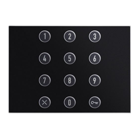
Numerisches tastatur-modul
Vorschau ausblenden Andere Handbücher für alpha 1168:
Inhaltsverzeichnis

Werbung

Verfügbare Sprachen
  • DE

Verfügbare Sprachen

  • DEUTSCH, seite 26
Mod.
1168
DS 1168-007
LBT 20488
MODULO TASTIERA NUMERICA
NUMERIC KEYPAD MODULE
MODULE CLAVIER NUMÉRIQUE
MÓDULO TECLADO NUMÉRICO
NUMERISCHES TASTATUR-MODUL
CIJFERTOETSENBORDMODULE
Sch./Ref. 1168/46
LIBRETTO DI INSTALLAZIONE
INSTALLATION MANUAL
NOTICE D'INSTALLATION
MANUAL DE INSTALACIÓN
INSTALLATIONSHANDBUCH
GEBRUIKSAANWIJZINGEN VOOR DE INSTALLATIE

Werbung

Inhaltsverzeichnis
loading

Inhaltszusammenfassung für urmet alpha 1168

  • Seite 1 Mod. 1168 DS 1168-007 LBT 20488 MODULO TASTIERA NUMERICA NUMERIC KEYPAD MODULE MODULE CLAVIER NUMÉRIQUE MÓDULO TECLADO NUMÉRICO NUMERISCHES TASTATUR-MODUL CIJFERTOETSENBORDMODULE Sch./Ref. 1168/46 LIBRETTO DI INSTALLAZIONE INSTALLATION MANUAL NOTICE D’INSTALLATION MANUAL DE INSTALACIÓN INSTALLATIONSHANDBUCH GEBRUIKSAANWIJZINGEN VOOR DE INSTALLATIE...
  • Seite 2: Inhaltsverzeichnis

    ITALIANO SOMMARIO DESCRIZIONE ..............................2 STRUTTURA ..............................3 DESCRIZIONE DEI MORSETTI ........................3 PROGRAMMAZIONE PER FUNZIONAMENTO IN MODALITÀ AUTONOMA (STAND ALONE) ..... 3 IMPOSTAZIONE DELLA PASSWORD MASTER ..................3 INGRESSO IN MODALITÀ DI PROGRAMMAZIONE .................. 4 PROGRAMMAZIONE OPZIONI RELÉ ......................4 MEMORIZZAZIONE CODICI DI ATTIVAZIONE ..................
  • Seite 3: Struttura

    STRUTTURA 1. Connettore per il cavetto di connessione moduli (IN); 2. Switch di programmazione (SW1); 3. Connettore per il cavetto di connessione moduli (OUT); 4. Ponticello per la scelta del funzionamento: in modalità autonoma (stand alone) in sistemi 2Voice ed Ipercom 5.
  • Seite 4: Ingresso In Modalità Di Programmazione

    Confermare con tasto Il dispositivo emette 3 bip di conferma, il colore del tasto da rosso ritorna blu e il dispositivo entra in funzionamento normale. Qualora si voglia modifi care la password master occorre rimuovere l’alimentazione dal dispositivo per un tempo minimo di 5 secondi, dopodiché ripetere la procedura descritta in precedenza. INGRESSO IN MODALITÀ...
  • Seite 5: Cancellazione Di Un Codice Di Attivazione

    Premere il tasto per confermare. Il dispositivo emette 3 bip di conferma e il colore del tasto passa in sequenza da rosso a blu a rosso. In caso di errore nell’inserimento del codice, il dispositivo emette un bip lungo e resta in attesa del codice corretto.
  • Seite 6: Programmazione Morsetto Fasce Orarie

    Premere il tasto per confermare. Digitare il nuovo codice di attivazione composto da 3 a 8 cifre. Premere il tasto per confermare. Il dispositivo emette 3 bip di conferma e il colore del tasto passa in sequenza da rosso a blu a rosso. In caso di errore nell’inserimento del codice, il dispositivo emette un bip lungo e resta in attesa del codice corretto.
  • Seite 7: Manutenzione

    MANUTENZIONE Si suggerisce di pulire il frontale con un panno umido non abrasivo. Non usare liquidi contenenti alcol o prodotti per la pulizia dei vetri. CARATTERISTICHE Tensione di alimentazione: ....................12 Vca o Vcc ±10% Assorbimento massimo: ..................... 260 mA @ 12 Vca 150 mA @ 12 Vcc Assorbimento massimo a riposo: ..................
  • Seite 8: Description

    ENGLISH INDEX DESCRIPTION ..............................8 STRUCTURE ..............................9 DESCRIPTION OF TERMINALS ......................... 9 PROGRAMMING FOR OPERATION IN STAND-ALONE MODE ..............9 MASTER PASSWORD PROGRAMMING PROCEDURE ................9 ACCESSING PROGRAMMING MODE ..................... 10 RELAY OPTIONS PROGRAMMING PROCEDURE .................. 10 ACTIVATION CODE STORAGE PROCEDURE ..................10 DELETING AN ACTIVATION CODE ......................
  • Seite 9: Structure

    STRUCTURE 1. Module connection wire connector (IN); 2. Programming switch (SW1); 3. Module connection wire connector (OUT); 4. Operation selection jumper: in stand-alone mode in 2Voice and Ipercom systems 5. Terminal board DESCRIPTION OF TERMINALS Common reference for time slots and door opener inputs Common contact relay 2 Normally closed contact relay 2 Normally open contact relay 2...
  • Seite 10: Accessing Programming Mode

    ACCESSING PROGRAMMING MODE Programming mode may be used to confi gure operation of the device and to save or edit access codes. Press in sequence. Enter the master password and press The device will beep 3 times to confi rm. The button turns from blue to red: the device is in programming state.
  • Seite 11: Deleting An Activation Code

    Either hold pressed for at least 5 seconds or leave the device inactive for more than 30 seconds to quit programming mode. The red button turns blue, the device will generate a long confi rmation beep and then return to normal operation.
  • Seite 12: Timeslot Terminal Programming Procedure

    Either hold pressed for at least 5 seconds or leave the device inactive for more than 30 seconds to quit programming mode. The red button turns blue, the device will generate a long confi rmation beep and then return to normal operation.
  • Seite 13: Specification

    SPECIFICATIONS Power voltage: ......................... 12 Vac o Vdc ±10% Maximum draw: ........................260 mA @ 12 Vac 150 mA @ 12 Vdc Maximum stand-by consumption: ..................105 mA @ 12 Vac 50 mA @ 12 Vdc Maximum switchable relay load: ..................12 Vca / 24 Vdc 5 A Inputs “A1”, “A2”...
  • Seite 14: Français

    FRANÇAIS SOMMAIRE DESCRIPTION .............................. 14 STRUCTURE ..............................15 DESCRIPTION DES BORNES ........................15 PROGRAMMATION POUR LE FONCTIONNEMENT EN MODE AUTONOME (STAND ALONE) ....15 PROGRAMMATION DU MOT DE PASSE MAITRE .................. 15 ACCES A LA MODALITE DE PROGRAMMATION ................... 16 PROGRAMMATION DES OPTIONS RELAIS ....................
  • Seite 15: Structure

    STRUCTURE 1. Connecteur pour câble de connexion des modules (IN) ; 2. Contacteur de programmation (SW1) ; 3. Connecteur pour câble de connexion des modules (OUT) ; 4. Cavalier de sélection du mode de fonctionnement : mode autonome (stand alone) dans les systèmes 2Voice et Ipercom 5.
  • Seite 16: Acces A La Modalite De Programmation

    Le dispositif émet 3 bips sonores de confi rmation, la touche de couleur rouge redevient de couleur bleue et le dispositif se met en mode de fonctionnement normal. Si l’on souhaite modifi er le mot de passe maître, il est nécessaire de mettre le dispositif hors tension pendant 5 secondes minimum, et ensuite répéter la procédure décrite précédemment.
  • Seite 17: Effacement D'un Code D'activation

    Le dispositif émet 3 bips sonores de confi rmation et la touche passe en séquence de la couleur rouge à la couleur bleue à la couleur rouge. En cas d’erreur de saisie du code, le dispositif émet un bip sonore prolongé et attend le code correct. Répéter la procédure susmentionnée si l’on souhaite saisir d’autres codes d’activation, en veillant à...
  • Seite 18: Programmation De La Borne Des Plages Horaires

    Appuyer sur la touche pour confi rmer. Le dispositif émet 3 bips sonores de confi rmation et la touche passe en séquence de la couleur rouge à la couleur bleue à la couleur rouge. En cas d’erreur de saisie du code, le dispositif émet un bip sonore prolongé et attend le code correct. Pour quitter la modalité...
  • Seite 19: Maintenance

    MAINTENANCE Il est conseillé de nettoyer les façades à l’aide d’un chiffon humide, non abrasif. Ne pas utiliser de liquides à base d’alcool ou de détergents pour les vitres. CARACTERISTIQUES Tension d’alimentation: ....................12 Vca o Vcc ±10% Absorption maximum: ......................260 mA @ 12 Vca 150 mA @ 12 Vcc Absorption maximum au repos: ..................
  • Seite 20: Español

    ESPAÑOL ÍNDICE DESCRIPCIÓN ............................. 20 ESTRUCTURA .............................. 21 DESCRIPCIÓN DE LOS BORNES ......................21 PROGRAMACIÓN PARA EL FUNCIONAMIENTO EN EL MODO AUTÓNOMO (STAND ALONE) ....21 CONFIGURACIÓN DE LA CONTRASEÑA MASTER ................21 ENTRADA EN EL MODO DE PROGRAMACIÓN ..................22 PROGRAMACIÓN DE LAS OPCIONES DEL RELÉ...
  • Seite 21: Estructura

    ESTRUCTURA 1. Conector para el cable de conexión módulos (IN); 2. Interruptor de programación (SW1); 3. Conector para el cable de conexión módulos (OUT); 4. Puente para la elección del funcionamiento: en el modo autónomo (stand alone) en sistemas 2Voice e Ipercom 5.
  • Seite 22: Entrada En El Modo De Programación

    El dispositivo emite 3 bips de confi rmación, el color de la tecla pasa de rojo otra vez a azul y el dispositivo entra en funcionamiento normal. Si se quiere modifi car la contraseña master, se debe cortar la alimentación del dispositivo durante un periodo mínimo de 5 segundos, y luego se debe repetir el procedimiento descrito más arriba.
  • Seite 23: Eliminación De Un Código De Activación

    En caso de error de introducción del código, el dispositivo emite un bip prolongado y queda en espera del código exacto. Repetir el procedimiento apenas descrito para introducir otros códigos de activación, con la precaución de usar nuevos números de asignación de memoria a los que se combinan los nuevos códigos.
  • Seite 24: Programación Del Borne De Las Franjas Horarias

    El dispositivo emite 3 bips de confi rmación y el color de la tecla pasa, en sucesión, de rojo a azul a rojo. En caso de error de introducción del código, el dispositivo emite un bip prolongado y queda en espera del código exacto.
  • Seite 25: Mantenimiento

    MANTENIMIENTO Se aconseja limpiar los frentes con un paño húmedo no abrasivo. No utilizar líquidos que contengan alcohol ni productos para la limpieza de cristales. CARACTERÍSTICAS Tensión de alimentación: ....................12 Vca o Vcc ±10% Absorción máxima: ......................260 mA @ 12 Vca 150 mA @ 12 Vcc Absorción máxima en reposo: ...................
  • Seite 26: Beschreibung

    DEUTSCH INHALT BESCHREIBUNG ............................26 AUFBAU ............................... 27 BESCHREIBUNG DER KLEMMEN ......................27 PROGRAMMIERUNG FÜR DEN BETRIEB IN UNABHÄNGIGER BETRIEBSART (STAND ALONE) .... 27 EINGABE DES MASTER-KENNWORTS ....................27 ZUGRIFF AUF DEN PROGRAMMIERMODUS ..................28 PROGRAMMAIERUNG DER RELAISOPTIONEN ..................28 SPEICHERN DER AKTIVIERUNGSCODES ....................
  • Seite 27: Aufbau

    AUFBAU 1. Verbinder für das Modulanschlusskabel (IN); 2. Programmier-Switch (SW1); 3. Verbinder für das Modulanschlusskabel (OUT); 4. Brücke für die Auswahl des Betriebs: unabhängige Betriebsart (stand alone) in 2Voice- und Ipercom-Systemen 5. Klemmenleiste. BESCHREIBUNG DER KLEMMEN Gemeinsamer Bezug der Zeitabschnitte und Türöffner Gemeinsamer Kontakt Relaisé...
  • Seite 28: Zugriff Auf Den Programmiermodus

    Soll das Master-Kennwort geändert werden, muss die Stromversorgung zum Gerät mindestens 5 Sekunden lang unterbrochen werden. Danach muss der zuvor beschriebene Vorgang wiederholt werden. ZUGRIFF AUF DEN PROGRAMMIERMODUS Vom Programmiermodus aus kann die Funktion des Geräts konfi guriert und die Zugangscodes können gespeichert oder geändert werden.
  • Seite 29: Löschen Eines Aktivierungscodes

    Bei fehlerhafter Eingabe des Codes sendet das Gerät einen langen Pfeifton aus und wartet auf die Eingabe des korrekten Codes. Wiederholen Sie den soeben beschriebenen Vorgang, wenn weitere Aktivierungscodes eingegeben werden sollen und achten Sie dabei darauf, neue Nummern der Speicherposition zu verwenden, mit denen die neuen Codes zu verknüpfen sind.
  • Seite 30: Programmierung Der Klemme Der Zeitabschnitte

    Die Taste zum Bestätigen drücken. Das Gerät sendet zur Bestätigung 3 Pfeiftöne aus und die Farbe der Taste wechselt der Reihe nach von rot auf blau auf rot. Bei fehlerhafter Eingabe des Codes sendet das Gerät einen langen Pfeifton aus und wartet auf die Eingabe des korrekten Codes.
  • Seite 31: Wartung

    WARTUNG Es wird empfohlen, die Frontseiten mit einem nicht scheuernden, feuchten Tuch zu reinigen. Keine alkoholhaltigen Flüssigkeiten oder Glasreiniger verwenden. MERKMALE Versorgungsspannung: ....................12 Vac o Vdc ±10% Maximale Stromaufnahme: ....................260 mA @ 12 Vac 150 mA @ 12 Vdc Max.
  • Seite 32: Nederlands

    NEDERLANDS INHOUDSOPGAVE BESCHRIJVING ............................32 CONSTRUCTIE ............................33 BESCHRIJVING VAN DE KLEMMENBORDEN ..................33 DE ALLEENSTAANDE WERKWIJZE (STAND ALONE) PROGRAMMEREN ..........33 HET MASTER-WACHTWOORD INSTELLEN ....................33 INGANG IN PROGRAMMEERMODUS ......................34 DE RELAIS-OPTIES PROGRAMMEREN ..................... 34 DE INSCHAKELCODE OPSLAAN ....................... 34 EEN INSCHAKELCODE VERWIJDEREN .....................
  • Seite 33: Constructie

    CONSTRUCTIE 1. Connector voor de aansluitkabel van de modules (IN) 2. Programmeertoets (SW1); 3. Connector voor de aansluitkabel van de modules (OUT); 4. Overbrugging om de werking in te stellen: alleenstaand (stand alone) in 2Voice- en Ipercom-systemen 5. Aansluitklemmenbord. BESCHRIJVING VAN DE KLEMMENBORDEN Gemeenschappelijke referentie voor de tijdreeksen en deuropener Gemeenschappelijk relaiscontact 2 Normaal gesloten relaiscontact 2...
  • Seite 34: Ingang In Programmeermodus

    Als u het master wachtwoord wenst te wijzigen, moet u de spanning naar het apparaat minstens 5 seconden uitschakelen en dan de hiervoor beschreven procedure herhalen. INGANG IN PROGRAMMEERMODUS In de programmeermodus kunt u de werking van het apparaat confi gureren en de toegangscodes opslaan of wijzigen.
  • Seite 35: Een Inschakelcode Verwijderen

    Als een verkeerde code wordt ingevoerd, laat het apparaat een lange bieptoon horen en wacht het op de juiste code. Herhaal de hierboven beschreven procedure als u nog andere codes wenst in te voeren maar vergeet niet om nieuwe nummers te gebruiken voor de plaats van het geheugen dat bij de nieuwe codes hoort.
  • Seite 36: Aansluitklem Voor Tijdreeksen Programmeren

    Voer de nieuwe inschakelcode in, van 3 tot 8 cijfers. Druk de toets in om te bevestigen. Het apparaat laat 3 bieptonen horen ter bevestiging en de rode toets wordt eerst rood, dan blauw en dan weer rood. Als een verkeerde code wordt ingevoerd, laat het apparaat een lange bieptoon horen en wacht het op de juiste code.
  • Seite 37: Manutenzione

    ONDERHOUD Wij raden aan om de deurplaat met een zachte, vochtige doek te reinigen. Gebruik geen alcohol bevattende producten of reinigingsproducten voor ramen. KENMERKEN Voedingspanning: ......................12 Vca of Vcc ±10% Maximum opgenomen stroom: ................... 260 mA @ 12 Vca 150 mA @ 12 Vcc Maximaal opgenomen stroom in ruststand: ................
  • Seite 38: Schema Di Collegamento Per Impianti In Modalità Autonoma (Stand Alone)

    SCHEMA DI COLLEGAMENTO PER IMPIANTI IN MODALITÀ AUTONOMA (STAND ALONE) CONNECTION DIAGRAM FOR SYSTEMS IN STAND-ALONE MODE SCHÉMA DE RACCORDEMENT POUR LES INSTALLATIONS EN MODE AUTONOME (STAND ALONE) ESQUEMA DE CONEXIÓN PARA SISTEMAS EN MODO AUTÓNOMO (STAND ALONE) ANSCHLUSSPLAN FÜR ANLAGEN IN UNABHÄNGIGER BETRIEBSART (STAND ALONE) VERBINDINGSSCHEMA VOOR ALLEENSTAANDE SYSTEMEN (STAND ALONE)
  • Seite 39: Note Legate Allo Schema

    A - Contatto Orologio D - Rete~ Clock switch Mains~ Interrupteur ‘horloge’ Secteur~ Interruptor ‘reloj’ Red~ “Zeitregler” Taste Netz~ Contact voor klok Net~ B - Azionamento Serratura E - Serratura elettrica Lock release Electric lock Ouverture Serrure Serrure electrique Abertura de la cerradura Cerradura eléctrica Öffnen Schloß...
  • Seite 40 For information on how to use the device implemented in 2Voice systems, download the respective instruction booklet from the Urmet website by scanning the following QR Code with the camera of your smartphone or tablet: Pour la confi guration du dispositif mis en place dans des systèmes 2Voice, télécharger les notices depuis le site Urmet, en lisant le Code QR suivant à...

Inhaltsverzeichnis