Inhaltsverzeichnis
Werbung
Verfügbare Sprachen
Verfügbare Sprachen
Quicklinks
Werbung
Inhaltsverzeichnis

Verwandte Anleitungen für MSI G31M3-Serie


Inhaltszusammenfassung für MSI G31M3-Serie
- Seite 1 G31M3 Series MS-7528 (V1.X) Mainboard G52-75281X4...
-
Seite 2: Trademarks
Alternatively, please try the following help resources for further guidance. Visit the MSI website for FAQ, technical guide, BIOS updates, driver updates, an d ot h er i n f orm at i on: h t t p: / / g l o ba l . -
Seite 3: Safety Instructions
Safety Instructions Always read the safety instructions carefully. Keep this User’s Manual for future reference. Keep this equipment away from humidity. Lay this equipment on a reliable flat surface before setting it up. The openings on the enclosure are for air convection hence protects the equip- ment from overheating. -
Seite 4: Fcc-B Radio Frequency Interference Statement
FCC-B Radio Frequency Interference Statement T h is eq uip men t h as been tested and found to c omply with the limits for a Class B digital device, pursuant to Part 15 of the FCC Rules. These limits are designed to provide reasonable protection against harmful interference in a residential installation. -
Seite 5: Weee (Waste Electrical And Electronic Equipment) Statement
WEEE (Waste Electrical and Electronic Equipment) Statement... -
Seite 8: Inhaltsverzeichnis
CONTENTS Copyright Notice ......................ii Tradema rks ........................ii Revision History ......................ii Technical Support ...................... ii Safety Instructions ....................iii FCC-B Radio Frequency Interference Statement ..........iv WEEE (Waste Electrical and Electronic Equipment) Statement ....... v English ........................En-1 Specifications .................... -
Seite 9: English
G31M3 User’s Guide English En-1... -
Seite 10: Specifications
Core™2 Duo/ Core™2 Quad/Pentium Dual-Core E2XXX and Celeron 400 LGA775 processors in LGA775 package. - Supports 4 pin CPU Fan Pin-Header with Fan Speed Control. (For the latest information about CPU, please visit http://global.msi.com.tw/index.php?func=cpuform) Supported FSB - 800/1066/1333 MHz Chipset ®... - Seite 11 Floppy - 1 floppy port - Supports 1 FDD with 360KB, 720KB, 1.2MB, 1.44MB and 2.88MB Connectors Back panel - 1 PS/2 m ouse port - 1 PS/2 keyboard port - 1 serial port (COM1) - 1 VGA port - 1 parallel port supporting SPP/EPP/ECP mode - 4 USB 2.0 Ports - 1 RJ-45 LAN Jack - 1 1394 port (optional)
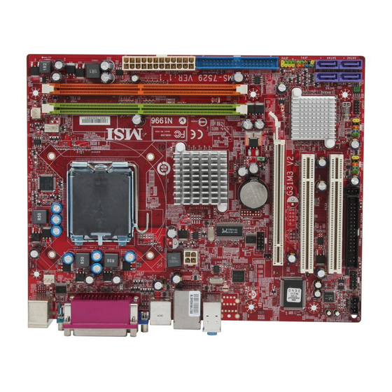
- Seite 12 M S-7528 M ainboard 1394 Parallel Port, LAN, (Optional) Port, p.En-17 p.En-16 p.En-16 RS-Out L-In L-Out CS-Out SS-Out Mouse/ Serial Port, VGA Port, USB ports, Audio, Keyboard, p.En-16 p.En-17 p.En-17 p.En-17 p.En-16 JSPD1, JTPM1, p.En-12 p.En-14 SYSFAN1, JPW1, CPU, CPUFAN1, p.En-9 p.En-14 p.En-5...
-
Seite 13: Central Processing Unit: Cpu
Central Processing Unit: CPU ® The m ainboard supports Intel processor. The mainboard uses a CPU socket called Socket 775 for easy CPU installation. If you do not have the CPU cooler, consult your dealer before turning on the com puter. For the latest information about CPU, please visit http://global.m si.com.tw/index.php? func=cpuform Important... - Seite 14 M S-7528 M ainboard CPU & Cooler Installation Procedures for Socket 775 1. The CPU socket has a plastic cap on it to protect the contact from damage. Before you have installed the CPU, always cover it to pro- tect the socket pin. 2.
-
Seite 15: Memory
Memory DDR2 Specification : 240-pin, 1.8v. Single channel definition : All DIMM slots are GREEN color. Dual channels definition : DIMM slot(s) on Channel A are marked in GREEN color. DIMM slot(s) on Channel B are m arked in Orange color. 64x2=128 pin 56x2=112 pin Important... - Seite 16 M S-7528 M ainboard Notch Volt En-8...
-
Seite 17: Connectors, Jumpers, Slots
Connectors, Jumpers, Slots Fan Power Connectors The fan power connectors support system cooling fan with +12V. The CPU FAN supports Smart FAN function. When connect the wire to the connectors, always take note that the red wire is the positive and should be connected to the +12V, the black wire is Ground and should be connected to GND. - Seite 18 M S-7528 M ainboard Serial ATA Connector This connector is a high-speed Serial ATA interface port. Each connector can connect to one Serial ATA device. Important Please do not fold the Serial ATA cable into 90-degree angle. Otherwise, data loss may occur during transmission. Front Panel Connectors These connectors are for electrical connection to the front panel switches and LEDs.
- Seite 19 Front USB Connector (Yellow) ® This connector, com pliant with Intel I/O Connectivity Design Guide, is ideal for con- necting high-speed USB interface peripherals such as USB HDD, digital cameras, MP3 players, printers, modems and the like. USB 2.0 Bracket (Optional) Important Note that the pins of VCC and GND must be connected correctly to avoid possible...
- Seite 20 M S-7528 M ainboard CD-In Connector This connector is provided for external audio input. GND R S/PDIF-Out Connector or S/PDIF-In Connector This connector is used to connect S/PDIF (Sony & Philips Digital Interconnect Format) interface for digital audio transm ission. SPDIF_out SPDIF_Out SPDIF Bracket (Optional)
- Seite 21 Clear CMOS Jumper There is a CMOS RAM onboard that has a power supply from an external battery to keep the data of system configuration. W ith the CMOS RAM, the system can automatically boot OS every time it is turned on. If you want to clear the system configuration, set the jumper to clear data.
- Seite 22 M S-7528 M ainboard Power Supply Attachment Before inserting the power supply connector, always make sure that all components are installed properly to ensure that no dam age will be caused. All power connectors on the mainbnoard have to connect to the ATX power supply and have to work together to ensure stable operation of the mainboard.
- Seite 23 PCI (Peripheral Component Interconnect) Express Slot The PCI Express slot supports the PCI Express interface expansion card. The PCI Express x 16 supports up to 4.0 GB/s transfer rate. The PCI Express x 1 supports up to 250 MB/s transfer rate. Mazarine PCI Express x16 Slots support PCI Express x 16 speed (PCI_E1) White PCI Express x 1 Slots support...
-
Seite 24: Back Panel
M S-7528 M ainboard Back Panel Mouse/Keyboard ® ® The standard PS/2 mouse/keyboard DIN connector is for a PS/2 mouse/keyboard. PS/2 Mouse connector (Green/ 6-pin female) PS/2 Keyboard connector (Purple/ 6-pin female) 1394 Port The IEEE1394 port on the back panel provides connection to IEEE1394 devices. The standard RJ-45 LAN jack is for connection to the Local Area Network (LAN). - Seite 25 Parallel Port A parallel port is a standard printer port that supports Enhanced Parallel Port (EPP) and Extended Capabilities Parallel Port (ECP) m ode. (25-pin female connector) Serial Port The serial port is a 16550A high speed comm unications port that sends/ receives 16 bytes FIFOs.
-
Seite 26: Bios Setup
M S-7528 M ainboard BIOS Setup This chapter provides basic information on the BIOS Setup program and allows you to configure the system for optimum use. You may need to run the Setup program when: * An error message appears on the screen during the system booting up, and requests you to run BIOS SETUP. - Seite 27 Entering Setup Power on the computer and the system will start POST (Power On Self Test) process. W hen the m essage below appears on the screen, press <DEL> key to enter Setup. Press DEL to enter SETUP If the message disappears before you respond and you still wish to enter Setup, restart the system by turning it OFF and On or pressing the RESET button.
- Seite 28 M S-7528 M ainboard The Main Menu ® ® Once you enter AMI or AW ARD BIOS CMOS Setup Utility, the Main Menu will appear on the screen. The Main Menu allows you to select from ten setup functions and two exit choices.
- Seite 29 <Enter> , a message as below appears: Press [Ok] to save the configurations and exit BIOS Setup utility. Important The configuration above are for general use only. If you need the detailed settings of BIOS, please see the manual in English version on MSI website. En-21...
-
Seite 30: Software Information
Utility m enu - The Utility menu shows the software applications that the mainboard supports. W ebSite menu- The W ebSite menu shows the necessary websites. Important Please visit the MSI website to get the latest drivers and BIOS for better system performance. En-22... -
Seite 31: Deutsch
G31M3 Benutzerhandbuch Deutsch... -
Seite 32: Spezifikationen
- Intel Core™2 Duo/ Core™2 Quad/Pentium Dual-Core E2XXX und Celeron 400 LGA775 Prozessoren für Sockel LGA775. - Unterstützt CPU Lüftersteuerung über 4 Stiftleisten. (W eitere CPU Inform ationen finden Sie unter http://global.msi.com.tw/index.php?func=cpuform) FSB (Front-Side-Bus) - 800/1066/1333 MHz Chipsatz ® - North-Bridge: Intel G31 Chipsatz ®... - Seite 33 Di sk et te - 1 Disketten Anschluss - Unterstützt 1 Diskettenlaufwerk mit 360KB, 720KB, 1.2MB, 1.44MB und 2.88MB Anschlüsse Hintere Ein-/ und Ausgänge - 1 PS/2 Mausanschluss - 1 PS/2 Tastaturanschluss - 1 Serielle Anschluss (COM1) - 1 VGA Anschluss - 1 Parallele Schnittstelle, unterstützt die Betriebsmodi SPP/EPP/ - 4 USB 2.0 Anschlüsse - 1 RJ-45 LAN Anschluss...
-
Seite 34: Übersicht Der Eingenschaften Der G31M3 Mainboard Series (Ms-7528 V1.X)
M S-7528 M ainboard Parallele 1394 LAN, Schnittstelle, (Optional) Port, S.D-16 S.D-17 S.D-16 L-In RS-Out L-Out CS-Out SS-Out M a u s - / Serielle USB ports, Audio, Tastatur, Schnittstelle, Anschluss, S.D-16 S.D-17 S.D-16 S.D-17 S.D-17 JSPD1, JTPM1, S.D-12 S.D-14 SYSFAN1, JPW1, CPU,... -
Seite 35: Hauptprozessor: Cpu
Sie Ihren Com puter anschalten. Um die neuesten Informationen zu unterstützten Prozessoren zu erhalten, besuchen Sie bitte http://global.msi.com.tw/index.php?func=cpuform Wichtig Überhitzung Überhitzung beschädigt die CPU und das System nachhaltig, stellen Sie stets ei ne korrekt e Funkti onsweis e des CP U Kühlers si cher, um di e CPU v or... - Seite 36 M S-7528 M ainboard CPU & Kühler Einbau für Sockel 775 1. Der CPU-Sockel besitzt zum Schutz eine Plastikabdeckung. Lassen Sie vor der Installtion diese Schutzkappe auf dem Sockel um Schäden zu verm eiden. 2. Entfernen Sie zuerst die Schutzkappe wie abgebildet in Pfeilrichtung. 3.
-
Seite 37: Speicher
Speicher DDR2 Spezifikation : 240-Pin, 1.8v. Single Channel : Um das Mainboard in Single Channel zu betreiben, nutzen Sie bitte die GRÜN gefärbten DIMM Bänke. Dual Channel : Um das Mainboard in Dual Channel zu betreiben,nutzen Sie bitte die GRÜN gefäbten (Kanal A) und ORANGE gefäbten DIMM Bänke (Kanal B) parallel. 64x2=128 Pin 56x2=112 Pin Wichtig... - Seite 38 M S-7528 M ainboard Notch Volt...
-
Seite 39: Anschlüsse, Steckbrücken Und Slots
Anschlüsse, Steckbrücken und Slots Stromanschlüsse für Lüfter Die Anschlüsseunterstützen aktive Systemlüfter mit + 12V. CPU FAN kann Smart FAN Funktion unterstützen. Wenn Sie den Anschluss herstellen, sollten Sie im mer darauf achten, dass der rote Draht der positive Pol ist, und mit +12V verbunden werden sollte, der schwarze Draht ist der Erdkontakt und sollte mit GND verbunden werden. - Seite 40 M S-7528 M ainboard Serial ATA Anschluss Der Anschluss ist ein Hochgeschwindigkeits Serielle-ATA Interface. Pro Anschluss kann ein S-ATA Gerät angeschlossen werden. Wichtig Bitte falten Sie das Serial ATA Kabel nicht in einem Winkel von 90 Grad, da dies zu Datenverlusten während der Datenübertragung führt Frontpanel Anschlüsse Diese Anschlüsse sind für das Frontpanel dienen zum Anschluss der Schalter und LEDs des Frontpaneels.
- Seite 41 USB Vorderanschluss (Gelb) ® Dieser Anschluss entspricht den Richtlinien des Intel I/O Connectivity Design Guide, ist bestens geeignet, Hochgeschwindigkeits- USB- Peripheriegeräte anzuschließen, wie z. B. USB Festplattenlaufwerke, Digitalkameras, MP3-Player, Drucker, Modems und ähnliches. USB 2.0 Slotblech (Optional) Wichtig Bitte beachten Sie, dass Sie die mit VCC (Stromführende Leitung) und GND (Erdleitung) bezeichneten Pins korrekt verbinden müssen, ansonsten kann es zu Schäden kommen Gehäusekontaktanschluss...
- Seite 42 M S-7528 M ainboard CD- Eingang Dieser Anschluss wird für externen Audioeingang zur Verfügung gestellt GND R S/PDIF- Ein-/ SPDIF- Ausgang Dieser Anschluss dienen zum Anschluss einer SPDIF (Sony & Philips Digital Intercon- nect Format) Schnittstelle zur digitalen Übertragung von Audiodaten. SPDIF_out SPDIF_Ausgang SPDIF Slotblech (Optional)
- Seite 43 Steckbrücke zur CMOS- Löschung Auf dem Mainboard gibt es einen sogenannten CMOS Speicher (RAM), der über eine Batterie gespeist wird und die Daten der Systemkonfiguration enthält. Er ermöglicht es dem Betriebssystem, m it jedem Einschalten automatisch hochzufahren. W ollen Sie die Systemkonfiguration löschen, verwenden Sie hierfür JBAT1 (Clear CMOS Jum per - Steckbrücke zur CMOS Löschung) Daten erhalten...
- Seite 44 M S-7528 M ainboard Zusätzlicher Hinweis Stromversorgung Bevor Sie eine Verbindung m it den Strom anschlüssen herstellen, stellen Sie im mer sicher, dass alle Komponenten ordnungsgem äß eingebaut sind, um jegliche Schäden auszuschließen. Alle Stromanschlüsse auf dem Mainboard müssen mit einem ATX Netzteil verbunden werden und müssen gemeinsam den stabilen Betrieb des Mainboards sicher stellen.
- Seite 45 PCI (Peripheral Component Interconnect) Express Slot Der PCI Express Slot unterstützt die PCI Express Schnittstelle Erweiterungskarten. Der PCI Express x 16 Slot unterstützt die Datenubertragunsraten von bis zu 4.0 GB/s. Der PCI Express x 1 Slot unterstützt die Datenubertragunsraten von bis zu 250 MB/s. dunkelblauen PCI Express x16 Steckplätze werden unterstützten eine Geschwindigkeit bis zu PCI Express x16 (PCI_E1)
-
Seite 46: Hinteres Anschlusspaneel
M S-7528 M ainboard Hinteres Anschlusspanel Maus-/Tastatur ® Die Standard PS/2 Maus/Tastatur Stecker Mini DIN ist für eine PS/2® Maus/Tastatur PS/2 Mausanschluss (Grün/ 6-Pin Buchse) PS/2 Tastaturanschluss (Lila/ 6-Pin Buchse) 1394 Port Das IEEE 1394 Port auf der hintere Anschlusspanel zu den Vorrichtungen IEEE1394. Die Standard RJ-45 Buchse ist für Anschlus zum an ein Lokales Netzwerk (Local Area Network - LAN). - Seite 47 Parallele Schnittstelle Die Parallele Schnittstelle ist eine Standard Druckerschnittstelle, die ebenso als En- hanced Parallel Port (EPP) und als Extended Capabilities Parallel Port (ECP) betrieben werden kann. (25-Pin Centronics Anschlussbuchse) Serielle Schnittstelle Bei der Seriellen Schnittstelle handelt es sich um eine 16550A Hochgeschwindigkeits- kommunikationsschnittstelle, die 16 Bytes FIFOs sendet/empfängt.
-
Seite 48: Bios Setup
M S-7528 M ainboard BIOS Setup Dieses Kapitel enthält Informationen über das BIOS Setup und ermöglicht es Ihnen, Ihr System optim al auf Ihre Anforderungen einzustellen. Notwendigkeit zum Aufruf des BIOS besteht, wenn: * W ährend des Bootvorgangs des Systems eine Fehlerm eldung erscheint und Sie zum Aufruf des BIOS SETUP aufgefordert werden. - Seite 49 Aufruf des BIOS Setups Nach dem Einsc halten beginnt der Com puter den POST (P ower On Self Test - Selbstüberprüfung nach Anschalten). Sobald die Meldung unten erscheint, drücken Sie die Taste <Entf>(<Del>) um das Setup aufzurufen. Press DEL to enter SETUP W enn die Nachricht verschwindet, bevor Sie reagieren und Sie möchten imm er noch ins Setup, starten Sie das System neu, indem Sie es erst AUS- und danach wieder ANSCHALTEN, oder die “RESET”-Taste am Gehäuse betätigen.
- Seite 50 M S-7528 M ainboard Das Hauptmenü ® ® Nachdem Sie das AMI oder AWARD BIOS CMOS Setup Utility, aufgerufen haben, erscheint das Hauptmenü. Es weist zehn Setup- Funktionen und zwei Arten das Menü zu verlassen auf. Verwenden Sie die Pfeiltasten, um im Menü zu navigieren und drücken Sie die Eingabetaste (<Enter>), um ein Unterm enü...
- Seite 51 W ählen Sie[Ok] und drücken Einter, um die (neuen) Einstellungen zu speichern und das BIOS Setup zu verlassen. Wichtig Die Konfiguration oben dienen nur generellen Zwecken. Wenn Sie detaillierte BIOS- Einstellungen benötigen, dann sehen Sie bitte das Handbuch in Englischer Sprache auf der MSI Website ein. D-21...
-
Seite 52: Software-Information
Gebrauchsmenmenü - das Gebrauchsmenü zeigt die SoftwareAnwendungen das die mainboard Unterstützungen. W ebSite Menü - das W ebsite Menü zeigt die notwendigen W ebsite. Wichtig Besichtigen Sie bitte die MSI Website, um die neuesten Treiber und BIOS für bessere System Leistung zu erhalten. D-22... -
Seite 53: Français
Installation Matériel G31M3 Guide d’Utilisation Français Fr-1... -
Seite 54: Spécificités
Celeron 400 LGA775 Processeurs de socket LGA775 - Supporte un connecteur de 4 pins du ventilateur de CPU avec le Contrôleur de la vitesse du ventilateur (Pour plus d’informations, veuillez visiter http://global.msi.com.tw/ index.php?func=cpuform) FSB Supporté - 800/ 1066/ 1333 MHz Chipset ®... - Seite 55 Installation Matériel Disquette - 1 port de disquette - Supporte 1 FDD avec 360KB, 720KB, 1.2MB, 1.44MB et 2.88MB Connecteurs Panneau arrière - 1 port souris PS/2 - 1 port clavier PS/2 - 1 port sérial (COM1) - 1 port VGA - 1 port parallèle qui supporte le m ode SPP/EPP/ECP - 4 ports USB 2.0 - 1 jack LAN RJ-45...
- Seite 56 La Carte M ère MS-7528 Port Port Parallèle, LAN, (Optional) 1394, p.Fr-17 p.Fr-16 p.Fr-16 RS-Out L-In L-Out CS-Out SS-Out Souris/ Port Série, Port VGA, Port USB, Audio, Clavier, p.Fr-17 p.Fr-17 p.Fr-16 p.Fr-17 p.Fr-16 JSPD1, JTPM1, p.Fr-12 p.Fr-14 SYSFAN1, JPW1, CPU, CPUFAN1, p.Fr-9 p.Fr-14...
-
Seite 57: Central Processing Unit: Cpu
Installation Matériel Central Processing Unit: CPU ® La carte mère supporte le processeur Intel . Elle utilise un Socket-775 pour l’installation. Si vous ne possédez pas de systèm e de refroidissem ent du CPU, contactez votre revendeur pour vous en procurer un et installet le avant d’allumer l’ordinateur. Pour pl us d’inform ations, veuill ez c onsulter: ht tp:/ /global. - Seite 58 La Carte M ère MS-7528 Procédure d’installation du CPU pour Socket 775: 1. La douille du CPU porte un chapeau en plastique pour la protéger des contacts qui lui causeraient des dom mages. Avant d’installé le CPU, couvrez-le pour protéger la goupille de la douille. 2.
-
Seite 59: Mémoire
Installation Matériel Mémoire DDR2 Spécification : 240-pin, 1.8v. Définition du canal : Tous les slots DIMM sont Verts. Définition de canaux double: Slot(s) DIMM sur le canal A est en Vert. Slot(s) DIMM sur le canal B est en Orange . 64x2=128 pin 56x2=112 pin Important... - Seite 60 La Carte M ère MS-7528 Entaille Volt Fr-8...
-
Seite 61: Connecteurs, Cavaliers, Slots
Installation Matériel Connecteurs, Cavaliers, Slots Connecteurs Alimentation du Ventilateur: Les connecteurs au système du ventilateur supportent la puissance du ventilateur avec +12V. Le CPUFAN1 du CPU supporte la fonctione Smart FAN. Quand vous reliez le fil aux connecteurs, notez que le fil rouge est positif et doit être relié au +12V, le fil noir est rectifié... - Seite 62 La Carte M ère MS-7528 Connecteur Série ATA Le connecteur SATA supporte le port Serial ATA de hautes performances. Chaque connecteur de SATA peut se connecter à un disque dur. Important Veuillez ne pas tordre le câble Série ATA à90 degrés, cela entraînera la perte de données lors des phases de transfert.
- Seite 63 Installation Matériel Connecteur USB en façade (Jaune) Ce connecteur est com patible avec IntelR I/O Connectivity Design Guide, est idéal pour la connexion de matériels possédant une interface USB tel que: disque dur USB, caméra digitale, imprimante, lecteur MP3 et bien d’autres périphériques. USB 2.0 Bracket (Optionnel) Important...
- Seite 64 La Carte M ère MS-7528 Connecteur CD-Entrée Ces connecteurs perm ettent l’audio input externe.. GND R Le connecteur de sortie S/PDIF ou entrée S/PDIF Ce connecteur est utilisée pour connecter l’interface S/PDIF (Format d’interconnexion numérique Sony et Philips) afin de transm ettre le son audio num érique. SPDIF_out SPDIF_Out SPDIF Bracket (Optional)
- Seite 65 Installation Matériel Cavalier Effacer CMOS Le CMOS RAM intégré reçoit une alimentation d’une batterie externe qui perm et de garder les données de configuration du système. Avec le CMOS RAM, le systèm e peut autom atiquem ent dém arrer avec les paramètres personnalisés du BIOS à chaque fois que le PC est allum é.
- Seite 66 La Carte M ère MS-7528 Attachement d’Alimentation d’Énergie: Avant d’insérer le connecteur d’alim entation d’énergie, assurez-vous toujours que tous les composants sont installés correctement afin de ne pas causer de dommage. Tous les connecteurs de puissance sur la carte mère doivent se relier à l’alimentation d’énergie d’ATX et doivent travailler ensem ble pour une opération stable.
- Seite 67 Installation Matériel Slot PCI Express (x16/ x4/ x1) Le slot PCI Express supporte la carte d'extension de l'interface PCI Express. Le PCI Express x 16 supporte un taux de transfert jusqu'a 4.0 GB/s. Le PCI Express x 1 supporte un taux de transfert jusqu'a 250 MB/s. bleu foncé...
-
Seite 68: Panneau Arrière
La Carte M ère MS-7528 Panneau Arrière Connecteur port Souris/ Clavier ® ® Le connecteur PS/2 souris/clavier DIN est conçu pour brancher un PS/2 souris/ clavier. Connecteur PS/2 Souris (Vert / 6-pin féminin) Connecteur PS/2 Clavier(Violet/ 6-pin féminin) Port 1394 Le port 1394 sur le panneau arrière fournit le raccordement pour les dispositifs 1394. - Seite 69 Installation Matériel Connecteur Port Parallèle : Un port parallèle est un port d’im prim ante standard qui supporte le port parallèle amélioré (EPP, Frhanced Parallel Port) et le m ode d’ECP(Extended Capabilities Paral- lel Port) (Connecteur 25-pin féminin) Connecteur Port Série Le port série est un port de communication 16550A à...
-
Seite 70: Configuration Du Bios
La Carte M ère MS-7528 Configuration du BIOS Ce chapitre vous informe sur le programme d’installation du BIOS et vous perm et de configurer le systèm e pour un usage optim um . Vous pouvez installer le programm e lorsque: * Un message d’erreur apparaît sur l’écran pendant que le système initialise et vous demande de mettre en marche l’INSTALLATION de BIOS. - Seite 71 Installation Matériel Entrer dans le Setup Allumez votre ordinateur, le système lance le processus de POST (Power On Self Test). Quand le m essage ci-dessous apparaît à l’écran, appuyez sur le bouton <DEL> pour entrer dans le setup. Press DEL to enter SETUP Si le m essage disparaît avant que vous ne puissiez entrer dans le setup, redémarrez vot re ordi nateur en appuyant sur le bout on RE SE T.
- Seite 72 La Carte M ère MS-7528 Menu Principal BIOS CMOS Setup Utility, le menu apparaît à ® ® Une fois entré dans le AMI ou AWARD l’écran. Le Menu perm et de sélectionner dix fonctions et deux c hoix de sortie de l’utilitaire.
- Seite 73 Pressez [ OK] pour sauver les configurations et sortir de l’installation du BIOS. Important Les configurations ci-dessus ne sont que pour l’usage général. Si vous avez besoin d’arrangements détaillés du BIOS, veuillez consulter le manuel (la version française) sur le Web de site de MSI. Fr-21...
-
Seite 74: Information De Logiciel
Menu de services – Il montre les applications logicielles supportées par la carte mère. Le menu du site Web – Il vous indique les sites webs utiles. Important Veuillez consulter le site Web de MSI pour obtenir les derniers pilotes et BIOS pour améliorer l’ exécution du système de votre ordinateur. Fr-22... -
Seite 75: Руководство Пользователя
G31M3 Руководство пользователя Русский Ru-1... -
Seite 76: Характеристики
® ICH7/ ICH7R(опционально) Память - DDR2 667/800 SDRAM (4GB Max) - 2 слота DDR2 DIMM (240конт / 1.8V) (За дополнительной информацией о совместимых компонентах посетите сайт http://global.msi.com .tw/index.php?func=testreport) LAN (опционально) - Поддержка Realtek RTL8111C 10/100/1000 Мб/с ® - Поддержка Realtek RTL8101E 10/100 Мб/с... - Seite 77 Флоппи - 1 флоппи порт - Поддержка 1 FDD с 360KB, 720KB, 1.2MB, 1.44MB и 2.88MB Коннекторы Задней панели - 1 PS/2 порт мыши - 1 PS/2 порт клавиатуры - 1 последовательный порт (COM1) - 1 порт VGA - 1 параллельный порт поддерживает режимы SPP/EPP/ECP - 4 порта...
- Seite 78 MS-7528 Системная плата Разъем 1394, LAN, параллельного порта, (опционально) p.Ru-16 p.Ru-16 p.Ru-17 RS-Out L-In L-Out CS-Out SS-Out Разъемы мыши/ COM, VGA, USB, Аудио разъемы, кливиатуры, p.Ru-17 p.Ru-17 p.Ru-17 p.Ru-16 p.Ru-16 JSPD1, JTPM1, p.Ru-12 p.Ru-14 SYSFAN1, JPW1, CPU, CPUFAN1, p.Ru-9 p.Ru-14 p.Ru-5 p.Ru-9 Память,...
-
Seite 79: Центральный Процессор: Cpu
установки процессора на ней установлен разъем под названием Socket 775. Если у вас нет процес сорного кулера, пожалуйста, свяж итесь с дилером с целью приобретения и его установки до того, как включите компьютер. Самую последнюю информацию о CPU можно получить на сайте http://global.msi. com .tw/index.php?func=cpuform Внимание... - Seite 80 MS-7528 Системная плата Установка процессора и вентилятора для Socket 775 Р азъем п роц ес сора зак рыт п лас тик овой к рышк ой, которая защищает контакты разъема от повреждений. При отсутствии процессора, необходимо всегда закрывать разъем пластиковой крышкой для защиты его контактов. 2.
-
Seite 81: Память
Память DDR2 Спецификация: 240-конт, 1.8v. Один канал памяти: все слоты DIMM зеленого цвета. Два канала памяти: слоты DIMM канала A зеленого цвета, слоты DIMM канала B оранжевого цвета. 64x2=128 конт 56x2=112 конт Внимание - Модули DDR2 не взаимозаменяемы с модулями DDR, и стандарт DDR2 не имеет... - Seite 82 MS-7528 Системная плата Notch Volt Ru-8...
-
Seite 83: Коннекторы, Перемычки, Разъемы
Коннекторы, перемычки, разъемы Разъемы питания вентиляторов Разъемы питания вентиляторов поддерживают вентиляторы с питанием +12В. Вентилятор процессора поддерживает функцию Smart FAN. При подключении необходимо помнить, что красный провод подключается к линии +12В, черный- к земле GND.Е сли на системной п лате установлена микрос хема ап паратного мониторинга, необходимо... - Seite 84 MS-7528 Системная плата Разъем Serial ATA Данный разъем является высокоскоростным портом интерфейса Serial ATA. Любой разъем Serial ATA может соединяться с одним устройством Serial ATA. Внимание Избегайте, пожалуйста, резких изгибов кабеля Serial ATA. В противном случае могут возникнуть потери данных при передаче. Коннекторы...
- Seite 85 Выносные порты USB (Желтый коннектор) Разъем, соответс твует спец ификации I ntel I/O Connectivity Design, идеально ® подходит для подключения таких высокоскоростных периферийных устройств, как USB HDD, цифровые камеры, MP3 плееры, принтеры и им подобные. USB 2.0 Bracket (опционально) Внимание Помните, что...
- Seite 86 MS-7528 Системная плата Коннектор CD-In Этот коннектор предназначен для подключения внешного входа аудио. GND R Коннектор входа/ выхода S/PDIF Этот разъем используется для подключения интерфейса S/PDIF (Sony & Philips Digital Interconnect Format) для передачи звука в цифровом формате. SPDIF_out SPDIF_Out S P D I F B r a c k e t (опционально)
- Seite 87 Перемычка сброса CMOS На плате установлена CMOS память с питанием от батарейки, хранящая данные о к онфигурац ии с ис темы. Данные, хранящ иеся в CMOS п амяти, требуютс я компьютеру для загрузки операционной системы при вк лючении. Если у вас возникает...
- Seite 88 MS-7528 Системная плата Подключение источника питания Перед подключением разъема питания, во избежание повреждений обязательно убедитесь, что все компоненты установлены правильно. Все разъемы питания должны быть подключены к блоку питаня ATX для обеспечения стабильной работы системной платы. 24-контактный разъем питания ATX Этот...
- Seite 89 Слот PCI (Peripheral Component Interconnect) Express Слот PCI Express поддерживает карты расширения интерфейса PCI Express. Слот PCI Express x 16 поддерживает скорость передачи данных до 4.0 ГБ/с. Слот PCI Express x 1 поддерживает скорость передачи данных до 250 МБ/с. Синие слоты PCI Express x16 поддерживают скорость...
-
Seite 90: Задняя Панель
MS-7528 Системная плата Задняя панель Разъемы мыши/клавиатуры Ст ан дартн ые р азъем ы DI N P S / 2 д ля п одк лю чения м ыш и / к лавиату ры с ® интерфейсом PS/2 ® Разъем PS/2 для мыши (6-контактнаый, зеленый... - Seite 91 Разъем параллельного порта Параллельный порт - это стандартный порт для принтера. Он поддерживает режимы EPP (усовершенствованный параллельный порт) и ECP (параллельный порт с дополнительными возможностями). (25-контактная розетка Сentronic) Разъем последовательного порта Это высокоскоростной последовательный порт связи 16550A с 16-битной передачи F I F O.
-
Seite 92: Настройка Bios
MS-7528 Системная плата Настройка BIOS В этой главе приводятся основные сведения о режиме настройки BIOS (BIOS SETUP), который позволяет установить оптимальлную конфигурацию системы. Этот режим может потребоваться в следующих случаях: * Во время загрузки системы появляется сообщение об ошибке с требованием запустить... - Seite 93 Вход в режим настройки Вк лючите п итание компьютера. При этом запуститс я п роц едура POST (Тест включения питания). Когда на экране появится приведенное ниже сообщение, нажмите клавишу <DEL> для входа в режим настройки. Press DEL to enter SETUP Если...
- Seite 94 MS-7528 Системная плата Main Menu (Главное меню) При входе в режим настройки BIOS от AMI или AWARD на экране отображается ® ® Главное меню. Главное меню позволяет выбрать десять функций настройки и имеет два варианта выхода. Для перемещения по пунктам используются клавиши со...
- Seite 95 Setup и нажмите <Enter>, появится следующее сообщение: Нажмите [Ok], чтобы сохранить конфигурацию и выйти из BIOS Setup. Внимание Приведенная выше конфигурация подходит для общего применения. Если же вам требуются более тонкие настройки BIOS, обратитесь к английской версии руководства на веб-сайте MSI. Ru-21...
-
Seite 96: Сведения О Программном Обеспечении
Utility m enu (Меню утилит) - Содержит прикладные программы для поддержки системной платы. W ebSite menu (Меню вебсайтов) - Содержит список необходимых вебсайтов. Внимание Если же вам требуются более тонкие настройки BIOS, обратитесь к английской версии руководства на веб-сайте MSI. Ru-22...