OTC Tools Motor-Rotor 1735B Betriebsanleitung
Montagebock für schwerlasten, ausgelegt als werkstückspannvorrichtung für motoren, getriebe, drehmomentwandler und hinterachsen von lastkraftwagen, traktoren und baumaschinen
Inhaltsverzeichnis
Verfügbare Sprachen
Verfügbare Sprachen
655 EISENHOWER DRIVE
OWATONNA, MN 55060-0995 USA
PHONE: (507) 455-7000
TECH. SERV.: (800) 533-6127
ORDER ENTRY: (800) 533-6127
INTERNATIONAL SALES: (507) 455-7223
FAX: (507) 455-7063
WEBSITE: WWW.OTCTOOLS.COM
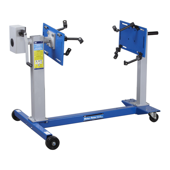
Motor-Rotor
Description: Heavy-duty repair stand designed as a work-holding device for engines, transmissions,
torque converters, and rear axles from trucks, tractors, and construction machinery.
The safety signal word designates the degree or level of hazard seriousness.
DANGER: Indicates an imminently hazardous situation which, if not avoided, will result in death or
serious injury.
WARNING: Indicates a potentially hazardous situation which, if not avoided, could result in death or
serious injury.
CAUTION: Indicates a potentially hazardous situation which, if not avoided, may result in minor or
moderate injury.
CAUTION: Used without the safety alert symbol indicates a potentially hazardous situation which, if not
avoided, may result in property damage.
© US Service Solutions, LLC
FAX: (800) 955-8329
FAX: (800) 283-8665
Universal Repair Stand
®
Maximum Capacity: 907 kg (2000 lbs.)
Weight: 131.5 kg (290 lbs.)
Explanation of Safety Signal Words
Form No. 565726
Parts List &
Operating Instructions
for:
Original Instructions
Sheet No.
1 of 5
Issue Date:
Rev. A August 9, 2012
1735B
Inhaltsverzeichnis

Inhaltszusammenfassung für OTC Tools Motor-Rotor 1735B
- Seite 9 English EC Declaration of Conformity I hereby declare that the equipment named here has been designed to SPX Service Solutions comply with the relevant sections of the above referenced specifications 655 Eisenhower Drive and is in accordance with the requirements of the Directive(s). Owatonna, Minnesota 55060-995 USA Signed by: in accordance with the following Directive(s):...
- Seite 19 English EC Declaration of Conformity I hereby declare that the equipment named here has been designed to SPX Service Solutions comply with the relevant sections of the above referenced specifications 655 Eisenhower Drive and is in accordance with the requirements of the Directive(s). Owatonna, Minnesota 55060-995 USA in accordance with the following Directive(s): Signed by: 2006/42/EC The Machinery Directive...
- Seite 29 English EC Declaration of Conformity I hereby declare that the equipment named here has been designed to SPX Service Solutions comply with the relevant sections of the above referenced specifications 655 Eisenhower Drive and is in accordance with the requirements of the Directive(s). Owatonna, Minnesota 55060-995 USA Signed by: in accordance with the following Directive(s):...
-
Seite 31: Erläuterung Der Signalwörter Zur Sicherheit
Formular Nr. 565726 655 EISENHOWER DRIVE OWATONNA, MN 55060-0995 USA TELEFON: +1 (507) 455-7000 Ersatzteilliste und KUNDENDIENST: +1 (800) 533-6127 FAX: +1 (800) 955-8329 Betriebsanleitung AUFTRAGSANNAHME: +1 (800) 533-6127 für: 1735B FAX: +1 (800) 283-8665 INTERNATIONALER VERKAUF: +1 (507) 455-7223 FAX: +1 (507) 455-7063 Original-Betriebsanleitung Motor-Rotor... -
Seite 32: Sicherheitsvorkehrungen
Ersatzteilliste und Betriebsanleitung Formular Nr. 565726 , Blatt 1 von 5, Rückseite Sicherheitsvorkehrungen VORSICHT: Um Verletzungen und/oder Sachschäden zu vermeiden: • Vor Inbetriebnahme des Montagebocks alle Sicherheitshinweise und Bedienungsanweisungen lesen und befolgen. Falls der Bediener die Anweisungen, Betriebsanleitung und Sicherheitshinweise nicht lesen kann, müssen ihm diese in seiner Muttersprache vorgelesen und erklärt werden. - Seite 33 Ersatzteilliste und Betriebsanleitung Formular Nr. 565726 Aufbauanleitung Die Artikelnummern in Klammern beziehen sich auf die Grafik auf dieser Seite. 1. 3/8-16 UNC x 88,9 mm (3.5 in.) lange Innensechskantschrauben benutzen, um die Hinterachse (Artikel 32) sicher an den Unterrahmen (18) zu schrauben. 2.
- Seite 34 Ersatzteilliste und Betriebsanleitung Formular Nr. 565726 , Blatt 2 von 5, Rückseite Betriebsanleitung . Sicherstellen, dass vor der Montage des Motors der Einrastmechanismus auf dem Montagebock eingerastet ist. Siehe Abbildung 1. 2. Den Schwerpunkt des Motors (oder die größte Gewichtskonzentration) bestimmen. 3.
-
Seite 35: Inspektion Und Wartung
Ersatzteilliste und Betriebsanleitung Formular Nr. 565726 Inspektion und Wartung VORSICHT: Um Verletzungen zu vermeiden: • Inspektionen und Reparaturen an diesem Montagebock dürfen nur von qualifiziertem Personal durchgeführt werden. • Nicht die Finger benutzen, um die Getriebebaugruppe mit Schmiermittel einzuschmieren, da Finger schnell vom Schneckengetriebe erfasst werden könnten. Inspektion Stützplatte Vor jeder Verwendung muss ein anerkannter Prüfer den... - Seite 36 Ersatzteilliste und Betriebsanleitung Formular Nr. 565726 , Blatt 3 von 5, Rückseite Teileliste Hinweis: Siehe Blatt 4 für die Teileliste des Getriebes. Für Einzelheiten zu Bedienung, Prüfung, Abbau, Wiederaufbau und vorbeugender Wartung, in der mitgelieferten Betriebsanleitung nachschlagen. Die Artikel in dieser Teileliste wurden sorgfältig geprüft und von OTC ausgewählt.
- Seite 37 Ersatzteilliste und Betriebsanleitung Formular Nr. 565726 Teile- Artikel- Menge Bezeichnung 537197 Abdeckung Unterlegscheibe—für 1/4 inch langen Passstift Innensechskantschraube—1/4-20 UNC x 15,9 mm (0.625 in.) Länge Federstift—12 mm x 65 mm (0.50 in. x 2.56 in.) Mutter—5/8-11 UNC 537205 Montageplatte 539591 Platte Innensechskantschraube—5/8-11 UNC x 44,5 mm (1.75 in.) Länge Kerbstift—6 mm x 60 mm (0.25 in.
-
Seite 38: Montage Des Getriebes
Ersatzteilliste und Betriebsanleitung Formular Nr. 565726 , Blatt 4 von 5, Rückseite Montage des Getriebes Teile- Artikel- Menge Bezeichnung Lagerbuchse Unterlegscheibe—für 1/2 inch langen Passstift Sicherungsschraube 1/2-13 x 31,8 mm (1.25 in.); Drehmoment auf 7/14 N•m (60/120 in. lbs.) anziehen Sicherungsmutter—1/2-13 UNC Unterlegscheibe—für 1/4 inch langen Passstift 548176... - Seite 39 English EC Declaration of Conformity I hereby declare that the equipment named here has been designed to SPX Service Solutions comply with the relevant sections of the above referenced specifications 655 Eisenhower Drive and is in accordance with the requirements of the Directive(s). Owatonna, Minnesota 55060-995 USA in accordance with the following Directive(s): Signed by:...
- Seite 49 English EC Declaration of Conformity I hereby declare that the equipment named here has been designed to SPX Service Solutions comply with the relevant sections of the above referenced specifications 655 Eisenhower Drive and is in accordance with the requirements of the Directive(s). Owatonna, Minnesota 55060-995 USA Signed by: in accordance with the following Directive(s):...