Omron H3CRA Bedienungsanleitung
Vorschau ausblenden
Andere Handbücher für H3CRA:
- Bedienungsanleitung (17 Seiten) ,
- Bedienungsanleitung (2 Seiten)
Werbung
Quicklinks
H3CR
-A
Model
-AS
SOLID-STATE TIMER
INSTRUCTION SHEET
UK/USA
Bedienungsanleitung
D
Manuel d'instructions
F
Thank you for purchasing this OMRON
product. This manual primarily describes
precautions required in installing and wiring
the timer. Before operating the product ,read
this manual thoroughly to acquire sufficient
knowledge of the product. Keep this manual
for future reference.
Bitte lesen Sie diese Betriebsanleitung
sorgfältig durch, bevor Sie mit dem Gerät
arbeiten.
Avant d'utiliser ce produit, veuillez, s'il
vous plait, lire attentivement ce manuel
pour vous familiariser avec le produit.
Karasuma Nanajo, Shimogyo-ku,
Kyoto 600, Japan
11P
OMRON Corporation
2244835-2C
15
66.6
6
52.3
R 0.5 max.
48
0.7
+0.6
45
□
48
0
φ39
44.8
Dimensions
UK/USA
A− Panel cutout dimensions
Applicable socket
Model P2CF-11
Front connection socket
Model P3GA-11
Back connection socket
Abmessungen
D
A− Frontplattenausschnitt
Verwendbare Sockel
P2CF-11
Frontseitige Klemmen
P3GA-11
Rückseitige Klemmen
Dimensions
F
A− Découpe du panneau
Socle
Modèle P2CF-11
Socle à connexion avant
Modèle P3GA-11
Socle à connexion arrière
Rating
UK/USA
Output ON: 0.3 W Output OFF: 0.2 W
Rated supply voltage
• 100 to 240 VAC (50/60 Hz)/100 to 125 VDC
Reset voltage : 10% max. of rated supply voltage
• 24 to 48 VAC (50/60 Hz)/12 to 48 VDC
Control outputs(Time limit contacts):
Operating voltage range
85% to 110% of rated supply voltage (90% to 110% at 12 VDC)
Power reset Minimum : power-opening time 0.1 s
Min. pulse width: 0.05 s
• Transistor output: Open collector (NPN/PNP)
Power consumption
H3CR-A
• 100 to 240 VAC/100 to 125 VDC(When at 240 VAC, 60 Hz)
Minimum load: 10 mA at 5 VDC (P level, reference value)
Relay ON: approx. 2.0 VA (1.6 W)
Ambient temperature
Relay OFF: approx. 1.3 VA (1.1 W)
• Operating: −10°C to 55°C (with no icing)
• 24 to 48 VAC/12 to 48 VDC(When at 24 VDC)
• Storage: −25°C to 65°C (with no icing)
Relay ON: approx. 0.8 W , Relay OFF: approx. 0.2 W
Ambient humidity Operating: 35% to 85%
H3CR-AS(When at 24 VDC)
UK/USA
Please comply strictly with the following instructions which are intended to ensure safe operation of the controller.
(1) Make sure the proper product is specified for the application.
(2) For correct use, do not subject the timer to the following conditions.
• Dramatic temperature fluctuations
• High humidity or where condensation may occur
• Severe vibration and shock
*1
H3CR
G.
S.
R.
• Where excessive dust, corrosive gas, or direct sunlight may be present
10
5
6
7
• Where there is danger of splashing of water, oil or any chemicals
(3) Store the Timer within the rated ranges given for the Timer model you are using. If the Timer is stored below
∼
2
2
−10°C, allow it to warm up for three hours at room temperature before turning ON the power supply.
(4) Mounting the Time Switch side-by-side may reduce the life expectancies of internal components.
(5) Use the Timer within the ambient operating temperature and ambient operating humidity ranges given for the
H3CR
G.
S.
R.
Timer model you are using.
10
5
6
7
(6) Separate the Timer from any sources of excessive static electricity, such as forming materials and pipes carrying
power or liquid materials.
2
2
(7) Maintain the variations in the power supply voltage to within the specified allowable range.
(8) If a voltage that exceeds the rating is applied, internal components may be destroyed.
(9) Wire all terminals correctly.
H3CR
G.
S.
R.
(10) Do not wire the terminals which are not used.
5
6
7
10
(11) Install and clearly label a switch or circuit breaker so that the operator can quickly turn OFF the power supply.
∼
(12) The exterior of the Timer may be damaged by organic solvents(such as thinners or benzene), strong alkali, or
2
2
strong acids.
(13) Confirm that the power and output indicators are operating normally. Depending on the operating environment,
H3CR
the indicators and plastic parts may deteriorate faster than expected, causing the indicators to fail. Periodically
G.
S.
R.
10
perform inspections and replacements.
5
6
7
(14) When disposing of the Timer, observe all local ordinances as they apply.
(15) When using the Timer in an area with excessive electronic noise, separate the Timer and input device as far as
2
2
possible from the noise sources. It is also recommended to shield the input signal wiring to prevent electronic
interference.
H3CR
(16) Cleaning
G.
S.
R.
5
6
7
10
Do not use paint thinner or the equivalent. Use standard grade alcohol to clean the product.
(17) Do not change the time unit, time range or operation mode while the Timer is in operation, otherwise
∼
malfunction could result. Be sure to turn off the power before making such changes.
2
2
(18) I/O Line connection
When connecting the contact or transistor for external input signal to the input terminals of the timer, pay
attention to the following points to prevent short-circuiting of the transformerless power supply.
⑩
When simultaneously inputting signals to more than one timer from the same input contact or transistor, the
phases of the power supplies must agree.(* 1) If the power supplies are not in phase, shortcircuit current will be
generated.
*3
⑪
For the power supply of an input device, use an isolation transformer(* 2), of which the primary and secondary
*2
windings are mutually isolated and the secondary winding is not grounded. ( * 3)
*4
⑫
The appropriate input terminal 5 (Gate input), 6 (Start input) or 7 (Reset input) uses power supply terminal 2 as
2
a common terminal and should therefore be connected by short-circuit to common terminal 2.
* 4 Voltage should be applied only across terminals 10 and 2. Do not apply voltage to any other terminals, and do not
∼
H3CR
connect terminals 5, 6, or 7 to terminal 10, or to any terminal other than terminal 2. Otherwise the internal
+
5
6
7
circuit of the timer may be damaged.
G.
S.
R.
*5
* 5 Do not connect a relay or other inductive load across the input supply points (terminals 2 and 10), or the internal
10
circuit of the timer may be damaged due to applied supply voltage.
(19) Power supply connection
⑬
Use a DC power supply having a ripple factor of 20% or less and supplying a mean voltage that is within the
rated operating voltage marked on the timer.
Make sure that the supply voltage is applied to the timer all at once, using contacts such as of a switch or relay.
Otherwise, the timer may not be able to perform power reset or its set time may be up when it should not.
X/b
T/a
X/a
(20) Please refer to the diagram shown on the left.( ) Interlock the power to the timer with a relay so that the timer
will not be left in a time-up condition for long periods. Leaving the timer in a time-up condition for a month or
longer, especially in places with high temperatures, may result in deterioration to internal parts, such as an
T
X
electrolytic capacitor.
x : R elay(Model MY)
(21) EN/IEC Standard Compliance
• Refer to the datasheet for the H3CR for cable selection and other conditions for compliance with EMC
standards.
• This is a class A product. In residential areas it may cause radio interference, in which case the user may be
required to take adequate measures to reduce interference.
• The power supply terminals and input terminals are not isolated. There is basic insulation between the power
supply terminals and output terminals.
• If double or reinforced insulation is required, use the double or reinforced insulation defined in IEC 60664 that
is suitable for the maximum applied voltage for the clearance, solid insulation, and other factors.
Suitability for Use
UK/USA
OMRON shall not be responsible for conformity with any standards, codes, or regulations that apply to the
combination of the products in the customer's application or use of the product. Take all necessary steps to
determine the suitability of the product for the systems, machines, and equipment with which it will be used.
Know and observe all prohibitions of use applicable to this product.
NEVER USE THE PRODUCTS FOR AN APPLICATION INVOLVING SERIOUS RISK TO LIFE OR PROPERTY
WITHOUT ENSURING THAT THE SYSTEM AS A WHOLE HAS BEEN DESIGNED TO ADDRESS THE
RISKS, AND THAT THE OMRON PRODUCT IS PROPERLY RATED AND INSTALLED FOR THE INTENDED
USE WITHIN THE OVERALL EQUIPMENT OR SYSTEM.
See also Product catalog for Warranty and Limitation of Liability.
Contact address
UK/USA
OMRON EUROPE B.V.
OMRON ASIA PACIFIC PTE. LTD.
Wegalaan 67-69, NL-2132 JD Hoofddorp The Netherlands
No. 438A Alexandra Road # 05-05/08(Lobby 2),
Phone 31-2356-81-300
Alexandra Technopark, Singapore 119967
FAX 31-2356-81-388
Phone 65-6835-3011
FAX 65-6835-2711
OMRON ELECTRONICS LLC
One Commerce Drive Schaumburg, IL 60173-5302 U.S.A
OMRON Corporation
Phone 1-847-843-7900
Shiokoji Horikawa, Shimogyo-ku, Kyoto 600-8530 JAPAN
FAX 1-847-843-7787
Safety Precautions
UK/USA
●Definition of Precautionary Information
Indicates a potentially hazardous situation which, if not
CAUTION
avoided, may result in minor or moderate injury or in
property damage.
●Precautionary Information
CAUTION
Switching arcs or relay heating may cause fire or explosion. Do not use
the Timer in the resence of inflammable or explosive gases.
The H3CR Series uses a transformerless power supply system. An
electrical shock may occur if an input terminal is touched while power is
being supplied.
The life of the output relay largely depends on the switching current and
other switch conditions.
Consider the actual application conditions and do not exceed the rated load
or electrical life. If the output relay is used beyond its service life, the
contacts may fuse or burning may occur. Also, never exceed the rated load
current. When using a heater, also place a thermal switch in the load circuit.
Minor electric shock, fire, or equipment failure may sometimes occur. Do
not disassemble, modify, or repair the Timer or touch any internal parts.
Do not remove the external case.
Tighten the terminal screws at the specified torque (1.08N•m).
Loose screws may occasionally result in fire.
( A,B,B2,C,D,E,G,J )
POWER
OUT
15
MODE
10
20
5
25
0
30
min
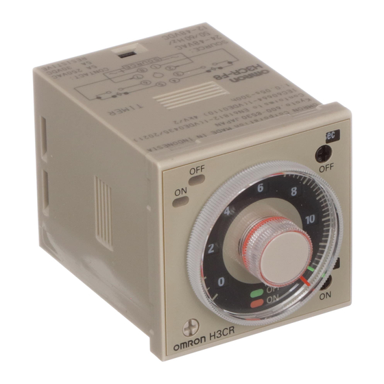
H3CR
(1.2, 3, 12, 30)
( sec,10s,min,
10min,hrs,10h )
Nomenclature
UK/USA
[mm]
+0.6
45
0
① Power indicator
② Output indicator
③ Rated time selector
A
④ Time unit selector
⑤ Setting dial (setting time value)
⑥ Operation mode selector
t=1~ 5
Note:If pointer is turned counterclockwise until
overranged, instantaneous output will be issued.
(zero point instantaneous operation)
Bezeichnungen der Teile
D
① Spannungsversorgungsanzeige
② Ausgangsanzeige
③ Zeitbereichsschalter
④ Zeiteinheitwahlschalter
⑤ Einstellscheibe (eigestellte Zeitdauer)
⑥ Betriebsartwahlschalter
Hinweis: Sofortausgang(Sofortbetrieb) kann durch
Drehung der Einstellscheibe auf 0 eigestellt werden.
Nomenclature
F
① Voyant d'alimentation en courant
② Voyant de puissance de sortrie
③ Sélecteur de temps nominal
④ Sélecteur de temps
⑤ Cadran de réglage (réglage du temps)
⑥ Sélecteur du mode de fonctionnement
Remarque :Use sortie instantanée est possible en
plaçant le cadran sur le réglage 0 (mode sortie
instantanée).
Nennversorgungsspannung
•100 bis 240 VAC (50/60 Hz)/100 bis 125 VDC
•24 bis 48 VAC (50/60 Hz)/12 bis 48 VDC
5 A at 250 VAC / 30 VDC
Betriebsspannungsbereich
0.15 A at 125 VDC
85% bis 110% der Nennversorgungsspannung (90% bis
resistive load (cos φ = 1)
110% bei 12 VDC)
Stromrücksetzzeit Minimum: Stromöffnungszeit 0,1 s
100 mA max. at 30 VDC max.,
Min. Impulsbreite: 0,05 s
residual voltage: 2 V max.
Leistungsaufnahme
H3CR-A
• 100 bis 240 VAC/100 bis 125 VDC (Bei 240 VAC, 60 Hz)
Relais EIN: ca. 2,0 VA (1,6 W)
Relais AUS: ca. 1,3 VA (1,1 W)
• 24 bis 48 VAC/12 bis 48 VDC (Bei 24 VDC)
Relais EIN: ca. 0,8 W , Relais AUS: ca. 0,2 W
Precautions for Safe Use
⑬
Vorsichtsmaßnahmen zum Gebrauch des Gerätes
D
OMRON ist nicht für Übereinstimmung mit Normen, Vorschriften oder Regularien verantwortlich, die für die
Kombination von Produkten in der Kundenanwendung oder Verwendung des Produkts gelten. Führen Sie alle
erforderlichen Schritte aus, um die Eignung des Produkts für die Anlagen, Geräte und Ausrüstungen, in denen es
verwendet werden soll, sicherzustellen. Beachten und befolgen Sie alle zutreffenden Verwendungseinschränkungen
für dieses Produkt.
NIEMALS DIE PRODUKTE FÜR EINE ANWENDUNG EINSETZEN, DIE ERNSTHAFTE RISIKEN FÜR
LEBEN ODER SACHWERTE BEINHALTET, OHNE SICHERZUSTELLEN, DASS DIE ANLAGE ALS GANZES
UNTER BERÜCKSICHTIGUNG SOLCHER RISIKEN KONZIPIERT IST UND DASS DAS OMRON-PRODUKT
RICHTIG BEWERTET UND INSTALLIERT IST, UM DIE VORGESEHENE FUNKTION INNERHALB DER
ANLAGE RICHTIG AUSZUFÜHREN.
Siehe auch Produktkatalog für Garantie und Haftpflichtbegrenzung.
Sicherheitsvorkehrungen
D
●Definition der Sicherheitshinweise
Weist auf eine potenziell gefährliche Situation, die, wenn
ACHTUNG
sie nicht vermieden wird, zu leichten oder mittelschweren
Verletzungen oder Sachschäden führen kann.
●Sicherheitshinweise
ACHTUNG
Schaltlichtbögen oder Relais-Erwärmung kann einen Brand oder eine Explosion
verursachen. Verwenden Sie den Timer nicht in der Nähe von brennbaren oder
explosiven Gasen.
Die H3CR-Serie verwendet einen transformatorlose Stromversorgung. Ein
elektrischer Schlag kann auftreten, wenn ein Eingangsanschluss berührt
wird, während er mit Strom versorgt wird.
Die Lebensdauer des Ausgangsrelais hängt weitgehend vom Schaltstrom und
anderen Schaltbedingungen ab.
Prüfen Sie die tatsächlichen Einsatzbedingungen und überschreiten Sie nicht die
Nennlast oder elektrische Lebensdauer. Wenn das Relais über seine Lebensdauer
verwendet wird, können die Kontakte schmelzen oder verbrennen. Überschreiten
Sie niemals den Nennlaststrom. Wenn Sie eine Heizeinrichtung verwenden,
platzieren Sie auch einen Thermoschalter im Lastkreis.
Ein leichter elektrischer Schlag, Brand oder Ausfall des Geräts kann
manchmal auftreten. Den Timer nicht zerlegen, modifizieren oder
reparieren. Keine internen Teile berühren.
Entfernen Sie nicht das externe Gehäuse.
Ziehen Sie die Anschlussschrauben mit dem angegebenen Drehmoment
(1,08N•m) an. Lose Schrauben könnten zu einem Feuer führen.
H3CR-A
H3CR-AS
S R
G
S R
G
∼
(−)
− +
(+)
(∼)
(∼)
∼
S R
G
− +
∼
− +
UK/USA
Connections
G : Gate input
Temporarily stops timing operation.
Open terminal
when not used.
S : Start input (Always connect)
Short-circuit terminal - with power-on start and power reset operation.
R : Reset input
Notes 1. Minimum input width is 0.05 sec.
External reset input.
2. Input condition are followings.
Open terminal
when not used.
Impedance when Short(ON) : 1 KΩ max.
⑦ Operating power
Residual voltage when Short(ON) : 1 V max.
⑧ Contact input signal connection
Impedance when open(OFF) : 100 KΩ min.
⑨ Solid-state input signal connection
Anschlußanordnung
D
G : Toreingang (Sockelkemme 5)
Hält den Zeitablauf an. Wird diese Funktion nicht benötigt, braucht
der Toreingang nicht angesch lossen werden.
S : Starteingang (Sockelklemme 6)
Bei dei Funktion Spannungsstart / Spannungsstopp muß der Starteingang
angesch lossen sein.
R : Rücksetzeingang (Sockelklemme 7)
Wird disse Funktion nicht benötigt, braucht der externe
Rücksetzeingang nicht angeschlossen werden.
⑦ Arbeitsspannung
⑧ Kontakt Eingangs Verbindung
⑨ Anschluß von Halbleitersignal-Eingängen
Brochage
F
G : Entrée porte
Pour arréter la temporisation.
Ouvrez la bovne
lorsqu'elle n'est pas utilisée.
S : Entrée de départ
Cout-circuitez les bornes
et
pour un départ á la mise sous tension
et une rimise á zéro á la coupure de tension.
R : Entrée de remise á zéro
Entrée de remise á zéro externe. Ouvrez la boune
lorsqu'elle n'est pas utilisée.
⑦ Tension d'alimentation
⑧ Connexion du signal d'entrée (contact)
⑨ Conexión de entradas de estada sólido
Wertung
D
H3CR-AS (Bei 24 VDC)
Ausgang EIN: 0,3 W Ausgang AUS: 0,2 W
Rücksetzspannung: 10% max. der Nennversorgungsspannung
Steuerausgänge(Zeitlimitkontakte):
5 A bei 250 VAC / 30 VDC
0,15 A bei 125 VDC
Ohmsche Last (cos = 1)
• Transistor-Ausgang: Offener Kollektor (NPN/PNP)
100 mA max. bei 30 VDC max.,
Restspannung: 2 V max.
Minimale Belastung: 10 mA bei 5 VDC (P-Pegel, Referenzwert)
Umgebungstemperatur
• Betrieb: −10°C bis 55°C (ohne Vereisung)
• Lagerung: −25°C bis 65°C (ohne Vereisung)
Luftfeuchtigkeit Betrieb: 35% bis 85%
Sicherheitsmaß-nahmen
D
Bitte folgen Sie genau den folgenden Hinweisen. Die gewährleisten eine sichere Funktion des Zeitrelais.
(1)
Stellen Sie sicher, dass das Produkt für die Anwendung geeignet ist.
(2)
Um einen korrekten Gebrauch zu gewährleisten, verwenden Sie den Timer nicht unter den folgenden Bedingungen.
• Hohe Temperaturschwankungen
• Hohe Luftfeuchtigkeit oder Orte, an denen Kondensation auftreten kann
• Schwere Vibrationen und Stöße
• Orte, an denen übermäßig viel Staub, korrosive Gase, oder direkte Sonneneinstrahlung vorhanden sind
• Orte, an denen die Gefahr von Spritzwasser, Öl oder anderen Chemikalien besteht
(3)
Bewahren Sie den Timer innerhalb der Nennwerte des von Ihnen verwendeten Timer Modells auf. Wenn der Timer
unter -10°C gelagert wird, lassen Sie ihn drei Stunden lang bei Raumtemperatur aufwärmen, bevor Sie die
Stromversorgung EIN schalten.
(4)
Eine Montage des Zeitschalters Seite an Seite könnte die Lebenserwartung der internen Komponenten verringern.
(5)
Verwenden Sie den Timer innerhalb der Bereiche für Umgebungstemperatur und Luftfeuchtigkeit des von Ihnen
verwendeten Timer Modells.
(6)
Trennen Sie den Timer von Quellen übermäßiger statischer Elektrizität, wie z.B. Formmaterialien und Leitungen,
die Strom oder Flüssigkeiten führen.
(7)
Halten Sie die Versorgungsspannung innerhalb des festgelegten zulässigen Bereichs.
(8)
Wenn eine Spannung, die den Nennwert übersteigt angelegt wird, könnten interne Komponenten zerstört werden.
(9)
Verdrahten Sie alle Anschlüsse ordnungsgemäß.
(10) Verdrahten Sie keine Anschlüsse, die nicht verwendet werden.
(11) Installieren und kennzeichnen Sie einen Schalter oder Leistungsschalter eindeutig, so dass der Bediener die
Stromversorgung schnell AUS schalten kann.
(12) Das Äußere des Timers kann durch organische Lösungsmittel (z.B. Verdünner oder Benzol), starke Laugen oder
starken Säuren beschädigt werden.
(13) Prüfen Sie, dass die Strom- und Ausgangsanzeigen normal funktionieren. Je nach Betriebsumgebung können die
Anzeigen und Kunststoffteile schneller als erwartet altern, was zu einem Ausfall der Anzeigen führen kann. Führen
Sie regelmäßig Inspektionen und Austausche durch.
(14) Beachten Sie alle örtlichen Verordnungen, wenn Sie den Timer entsorgen.
(15) Wenn der Timers in einem Bereich mit übermäßigen elektronischen Störungen verwendet wird, trennen Sie den
Timer und das Eingabegerät so weit wie möglich von den Störquellen. Es wird auch empfohlen, das Eingangssignal
abzuschirmen, um elektronische Störungen zu verhindern.
(16) Reinigung
Verwenden Sie keine Verdünnung für Lacke o.ä., sondern nur Reinigungsalkohole.
(17) Ändern Sie niemals die Zeiteinheit, den Zeitbereich oder den Arbeitsmodus während das Gerät arbeitet, andernfalls wird
eine Fehlfunktion daraus resultieren. Stellen Sie sicher, daß bei derartigen Änderungen die Netzspannung abgeschaltet ist.
(18) Leitungsanschluß für Ein-/Ausgang.
Falls Sie einen Kontakt oder einen Transistor als externes Eingangssignal für das Zeitrelais benutzen, beachten Sie die
folgenden Punkte um Kurzschlüsse durch transformatorlose Netzteile zu vermeiden.
⑩
Bei gleichzeitigem Signaleingang von einern Eigangsanschluß oder Eingangstransistor an mehr als ein Zeitrelais müssen die
Phasen der Stromquellen übereinstimmen.( * 1) Falls die Stromquellen nicht gleichphasig sind, wird Kurzschlußstorm erzeugt.
⑪
Verwenden Sie einen Netztransformator( * 2) mit voneinander isolierter Primärund Sekundärwicklung und ungeerdeter
Sekundärwicklung als Spannungsversorgung.( * 3)
⑫
Die Eingangsklemmen 5 ( Toreingang), 6 (Starteingang) oder 7 (Rücksetzeingang) verwenden die Netzklemme 2 als
gemeinsamen Punkt (com.) und müssen deshalb mittels Kurzschlußbrücke mit der Klemme 2 verbunden werden.
* 4
Spannung sollte nur zwischen den Klemmen 10 und 2 angelegt werden. Schließen Sie niemals Spannung an andere
Klemmen an, und verbinden Sie niemals die Klemmen 5, 6, oder 7 mit der Klemme 10 oder irgendeiner anderen als der Klemme
2. Andernfalls wird der interne Schaltkreis oder das Zeitrelais zerstört.
* 5
Klemmen Sie kein Relais oder eine induktive Last zwischen die Eingangsklemmen ( Klemmen 10 und 2 ) , der interne
Schaltkreis des Zeitrelais könnte durch die Versorgungsspannung zerstört werden.
(19) Anschluß der Netzspannung
Verwenden Sie eine Gleichspannungsversorgung mit einer Restwelligkeit von 20% oder weniger und eine mittlere
Spannung, die innerhalb des angegebenen Bereiches für die Betriebsspannung des Zeitrelais liegt. Stellen Sie sicher,
daß die Spannung über die ganze Zeit am Zeitrelais ansteht. Verwenden Sie Kontakte, wie z.B. ein Relais.
Andernfalls kann das Zeitrelais nicht ordentlich arbeiten. Es könnte z.B. die Netzrückstellung oder der Endzeitpunkt
geschaltet werden, obwohl die Zeit noch nicht abgelaufen ist.
(20) Bitte beachten Sie die nebenstehende Zeichnung.(
⑬
) Verknüpfen Sie das Netz über ein Relais mit dem Zeitrelais, so
daß es niemals über eine längere Zeit (ein Monat oder länger) in der Funktion „Zeit abgelaufen" stehen bleibt.
Es könnten sonst Bauteile wie z.B. Elektrolytkondensatoren vorzeitig zerstört werden.
(21) EN/IEC Standard-Konform
• Lesen Sie das H3CR Datenblatt für die Kabelauswahl und andere Bedingungen für die Einhaltung der EMV-Normen.
• Dies ist ein Produkt der Klasse A. Beim Betrieb des Gerätes in häuslichen Umgebungen können Funkstörungen
auftreten. Die Beseitigung dieser Störungen geht zu Lasten des Benutzers.
• Die Spannungsversorgungsanschlüsse und Eingangsanschlüsse sind nicht isoliert. Es gibt eine einfache
Isolierung zwischen den Versorgungsspannungsanschlüssen und Ausgangsanschlüssen.
• Wenn eine doppelte oder verstärkte Isolierung erforderlich ist, verwenden Sie die in IEC 60664 definierte doppelte
oder verstärkte Isolierung, die für die maximale angelegte Spannung für den Abstand, die stabile Isolierung und
andere Faktoren geeignet ist.
I
Kontakt Adresse
D
OMRON EUROPE B.V.
Wegalaan 67-69, NL-2132 JD Hoofddorp The Netherlands
Phone 31-2356-81-300
FAX 31-2356-81-388
OMRON Corporation
Shiokoji Horikawa, Shimogyo-ku, kyoto 600-8530 JAPAN
●Informations sur les précautions à prendre
ATTENTION
●Précautions à prendre
Les arcs de commutation ou la chauffe de relais peut provoquer un incendie ou une
explosion. Ne pas utiliser la minuterie en présence de gaz inflammables ou explosifs.
La série H3CR utilise un système d'alimentation sans transformateur. Un choc électrique
peut se produire si une borne d'entrée est touchée lorsqu'elle est sous tension.
La durée de vie du relais de sortie dépend essentiellement du courant de
commutation et d'autres conditions de l'interrupteur.
Tenez compte des conditions réelles d'application et ne dépassez pas la charge
nominale ou la durée de vie électrique. Si le relais de sortie est utilisé au-delà de
sa durée de vie, les contacts risquent de fondre ou des brûlures peuvent se
produire. En outre, ne dépassez jamais le courant de charge nominale. Lors de
l'utilisation d'un appareil de chauffage, placez également un interrupteur
thermique dans le circuit de charge.
Des chocs électriques mineurs, du feu, ou des pannes d'équipement
peuvent parfois se produire. Ne pas démonter, modifier ou réparer la
minuterie et ne pas toucher aux pièces internes.
Ne retirez pas le boîtier externe.
Serrez les vis des bornes au couple spécifié (1,08N•m).
Des vis desserrées risqueraient d'entraîner un incendie.
Timing charts
t
UK/USA
―
(START)
A.
Mode
Signal ON delay
―
(RESET)
operation
―
* 1 :Output indicator
*1(out)
* 2 :(power)indicator
*3
*2(power)
* 3 :flicker
B.
t
t
t
t
t
t
t
t
Mode
Signal ON flicker, OFF
―
(START)
start operation
―
* 1 :Output indicator
(RESET)
* 2 :(power)indicator
―
*1(out)
* 3 :flicker
*3
*2(power)
t
t
t
t
t
t
t
t
B2.
Mode
Signal ON flicker, ON
―
(START)
start operation
―
(RESET)
* 1 :Output indicator
―
* 2 :(power)indicator
*1(out)
* 3 :flicker
*3
*2(power)
t
t
t-a
t
C.
Mode
Signal ON•OFF delay
―
operation
(START)
* 1 :Output indicator
―
* 2 :(power)indicator
*1(out)
*3
*3
*3
* 3 :flicker
*2(power)
D.
t
Mode
Signal OFF delay
―
operation
(START)
* 1 :Output indicator
―
* 2 :(power)indicator
*1(out)
*3
* 3 :flicker
*2(power)
t
t
E.
Mode
Signal ON interval
―
operation
(START)
* 1 :Output indicator
―
* 2 :(power)indicator
*1(out)
*3
*3
* 3 :flicker
*2(power)
t
t
t-a
t
G.
Mode
Signal ON•OFF delay
―
operation
(START)
―
* 1 :Output indicator
*1(out)
*3
*3
*3
* 2 :(power)indicator
*2(power)
* 3 :flicker
a<t
t
J.
―
Mode
One-shot Output
(START)
operation
―
(RESET)
* 1 :Output indicator
―
* 2 :(power)indicator
1s±0.6s(fixed)
*1(out)
* 3 :flicker
*3
*2(power)
Classement
F
Tension d'alimentation nominale
• 100 à 240 Vc.a. (50/60 Hz)/100 à 125 Vc.c.
• 24 à 48 Vc.a. (50/60 Hz)/12 à 48 Vc.c.
Plage de tension de fonctionnement
85% à 110% de tension d'alimentation nominale (90% à
110% à 12 Vc.c.)
RAZ de l'alimentation minimum : temps de coupure 0,1 s
Largeur d'impulsion min. : 0,05 s
Consommation
H3CR-A
• 100 à 240 Vc.a./100 à 125 Vc.c.(À 240 Vc.a., 60 Hz)
Relais ON : environ 2,0 VA (1,6 W)
Relais OFF : environ 1,3 VA (1,1 W)
• 24 à 48 Vc.a./12 à 48 Vc.c.(À 24 Vc.c.)
Relais ON : environ 0,8 W , Relais OFF : environ 0,2 W
Précaution d'usage pour la sécurité
F
Veuillez suivre précisément les instructions suivantes afin d'utiliser correctement la minuterie.
(1)
Assurez-vous que le produit convient à l'application.
Pour une utilisation correcte, ne soumettez pas la minuterie aux conditions suivantes.
(2)
• Fluctuations de température importantes
• Humidité élevée ou risque de condensation
• Fortes vibrations et chocs
• Présence de poussière excessive, gaz corrosifs, ou lumière directe du soleil
• Risques d'éclaboussures d'eau, d'huile ou de produits chimiques
(3)
Stockez la minuterie dans les plages nominales indiquées pour le modèle de minuterie que vous utilisez. Si la
minuterie est stockée en dessous de -10 °C, laissez-la se réchauffer pendant trois heures à température ambiante
avant de la mettre sous tension.
(4)
Le montage de l'interrupteur temporisé côte-à-côte peut réduire la durée de vie des composants internes.
(5)
Utilisez la minuterie dans les plages de température et d'humidité de fonctionnement ambiantes données pour le
modèle de minuterie que vous utilisez.
(6)
Séparez la minuterie de toute source d'électricité statique excessive, telle que matériaux formants et tuyaux
transportant du courant ou des matières liquides.
(7)
Maintenir les variations de tension d'alimentation à l'intérieur de la plage admissible spécifiée.
(8)
Si une tension dépassant la valeur nominale est appliquée, les composants internes risquent d'être détruits.
(9)
Câblez correctement toutes les bornes.
(10) Ne câblez pas les bornes non utilisées.
(11) Installez et marquez clairement un interrupteur ou un disjoncteur de sorte que l'opérateur puisse couper
rapidement l'alimentation.
(12) L'extérieur de la minuterie peut être endommagé par les solvants organiques (tels que des diluants ou du
benzène), des alcalins, ou des acides forts.
(13) Vérifiez que les voyants d'alimentation et de sortie fonctionnent normalement. Selon l'environnement
d'exploitation, les voyants et les pièces en plastique peuvent se dégrader plus rapidement que prévu, provoquant
l'échec des voyants. Effectuez régulièrement des vérifications et des remplacements.
(14) Lorsque vous éliminez la minuterie, respectez tous les règlements locaux qui s'appliquent.
(15) Lorsque vous utilisez la minuterie dans une zone de bruit électronique excessif, séparez le plus possible la
minuterie et le dispositif d'entrée des sources de bruit. Il est également recommandé de blinder le câblage du
signal d'entrée pour éviter les interférences électroniques.
(16) Nettoyage
N'utilisez pas des solvants de peinture ou équivalents. Utilisez des produits à base d'alcool.
(17) Ne changez pas le temps, la gamme de temps ou la fonction alors que la minuterie est en fonctionnement. Sinon un
dysfonctionnement pourrait survenir. Soyez sûr d'être en position off.
(18) Connexions des E/S:
Lors de la connexion de sorties contacts ou transistors sur le signal d'entrée de la minuterie faites attention aux
points suivants pour éviter tout court-circuit sans transfomateur d'alimentation.
⑩
Lors de l'entrée simultanée de signaux à plusieurs minuteries à partir du même contact ou transistor, les phases
des alimentations doivent correspondre. Si elles ne sont pas en phase, du courant de courtcircuit sera produit.( * 1)
⑪
Utiliser un transformateur( * 2) d'alimentation avec isolement mutuel de le bobine primaire et secondaire et avec
le bobine secondair non mise à la terre comme source d'alimentation de l'appareil d'entrée.( * 3)
⑫
Les bornes d'entrées 5 (Entrée porte), 6 (Entrée départ), 7 (Remise à zéro), utilisent la borne d'alimentation 2
comme borne de commun et par conséquent doivent être liée à la borne du commun 2.
* 4 La tension ne peut être appliquée qu'entre les bornes 10 et 2. N'appliquez pas de tension à toute autre borne, et ne
connectez pas les bornes 5, 6, ou 7 à la borne 10, ou toute autre borne que la borne 2. Sinon le circuit intérieur de
la minuterie pourrait être endommagé.
* 5 Ne connectez pas un relais ou toute autre charge inductive en ligne avec les entrées d'alimentations (bornes 2 et
10), ou le circuit intérieur de la minuterie pourrait être endommagé.
(19) Connexion de l'alimentation
Utilisez une alimentation Vc.c. avec un facteur d'ondulation inférieur à 20% délivrant la tension nominale
marquée sur le produit.
Assurez vous d'alimenter la minuterie d'un coup en utilisant des contacts tels que des relais ou des interrupteurs.
Sinon, la fonction remise à zéro ou le temps réglé pourrait être altérés.
(20) Veuillez vous référer au schéma de gauche.(
minuterie ne restera pas durant une longue période en position temporisation finie. Le maintien dans cette
position durant un mois ou plus pourrait, spécialement dans une ambiance avec une haute température, détériorer
des composants internes tel que les condensateurs.
(21) Conformité aux normes EN/CEI
• Reportez-vous à la fiche technique du H3CR pour le choix des câbles et autres conditions pour la conformité aux
normes CEM.
• Il s'agit d'un produit de classe A. Dans les zones résidentielles des interférences radio peuvent se produire,
auquel cas l'utilisateur peut être amené à prendre des mesures adéquates pour réduire les interférences.
• Les bornes d'alimentation et les bornes d'entrée ne sont pas isolées. Une isolation de base est présente entre les
bornes d'alimentation et les bornes de sortie.
• Si une isolation double ou renforcée est nécessaire, utilisez l'isolation double ou renforcée définie dans la norme CEI
60664 qui est adaptée à la tension maximale appliquée pour le dégagement, une solide isolation, et autres facteurs.
Conditions d'utilisation
F
OMRON ne sera pas responsable de la conformité avec toutes normes, codes ou règlements qui s'appliquent à
l'association des produits dans l'application du client ou à l'utilisation du produit. Prendre toutes les mesures
nécessaires pour déterminer l'adéquation du produit vis-à-vis des systèmes, machines et équipements avec qui il
sera utilisé. Connaître et respecter toutes les interdictions d'usage applicables à ce produit.
NE JAMAIS UTILISER LES PRODUITS POUR UNE APPLICATION PRÉSENTANT UN RISQUE SÉRIEUX
POUR LA VIE OU LES BIENS SANS S'ASSURER QUE LE SYSTÈME ENTIER A ÉTÉ CONÇU POUR FAIRE
FACE AUX RISQUES ET QUE LE PRODUIT OMRON EST ÉVALUÉ ET INSTALLÉ CONVENABLEMENT
POUR L'USAGE ENVISAGÉ DANS L'ENSEMBLE DE L'ÉQUIPEMENT OU DU SYSTÈME.
Voir également le catalogue des produits pour la garantie et les limites de la responsabilité.
Adresse du contact
F
OMRON EUROPE B.V.
Wegalaan 67-69, NL-2132 JD Hoofddorp Pays-Bas
Tél. 31-2356-81-300
FAX 31-2356-81-388
OMRON Corporation
Shiokoji Horikawa, Shimogyo-ku, Kyoto 600-8530 JAPON
Consignes de sécurité
F
Indique des situations potentiellement dangereuses qui, si
elles ne sont pas évitées, peuvent entraîner des blessures
mineures ou modérées ou des dommages matériels.
ATTENTION
Zeitablauf
Tableaux de minutage
D
F
A.
A.
Modus
Zeitverzögerter
Mode
Signal ON,
Betrieb des EINSignals
déclenchement retardé
* 1 :Ausgangsanzeige
* 1 :Voyant de sortie
* 2 :Netzanzeige
* 2 :Voyant d'alimentation
* 3 :blinkend
* 3 :clignotant
B.
B.
Modus
Signal EIN blinkend
Mode
Signal ON clignote
(Aus-Start-Betrieb)
(déclenchement annulé)
* 1 :Ausgangsanzeige
* 1 :Voyant de sortie
* 2 :Netzanzeige
* 2 :Voyant d'alimentation
* 3 :blinkend
* 3 :clignotant
B2.
B2.
Modus
EIN-Signal blinkend,
Mode
Signal ON clignote,
EIN Betriebsbeginn
déclenchement
* 1 :Ausgangsanzeige
* 1 :Voyant de sortie
* 2 :Netzanzeige
* 2 :Voyant d'alimentation
* 3 :blinkend
* 3 :clignotant
C.
C.
Modus
Zeitverzögerter
Mode
Signal ON/OFF
Betrieb des EIN/
déclenchement retardé
AUSSignals
* 1 :Voyant de sortie
* 1 :Ausgangsanzeige
* 2 :Voyant d'alimentation
* 2 :Netzanzeige
* 3 :clignotant
* 3 :blinkend
D.
D.
Modus
Zeitverzögerter
Mode
Signal OFF
Betrieb des
déclenchement retardé
AUS-Signals
* 1 :Voyant de sortie
* 1 :Ausgangsanzeige
* 2 :Voyant d'alimentation
* 2 :Netzanzeige
* 3 :clignotant
* 3 :blinkend
E.
E.
Modus
Intervallbetrieb
Mode
Signal ON
des EINSignals
fonctionnement
* 1 :Ausgangsanzeige
intermittent
* 2 :Netzanzeige
* 1 :Voyant de sortie
* 3 :blinkend
* 2 :Voyant d'alimentation
* 3 :clignotant
G.
G.
Modus
Signal EIN • AUS
Mode
Signal ON•Fonctionne-
Schaltverzögerung
ment temporisé OFF
* 1 :Voyant de sortie
Betrieb
* 1 :Ausgangsanzeige
* 2 :Voyant d'alimentation
* 2 :Netzanzeige
* 3 :clignotant
* 3 :blinkend
J.
J.
Modus
Einmal-Ausgang
Mode
Fonctionnement de
Betrieb
sortie Un coup
* 1 :Ausgangsanzeige
* 1 :Voyant de sortie
* 2 :Netzanzeige
* 2 :Voyant d'alimentation
* 3 :blinkend
* 3 :clignotant
H3CR-AS (À 24 Vc.c.)
Sortie ON : 0,3 W Sortie OFF : 0,2 W
Tension de RAZ : 10% max. de la tension d'alimentation nominale
Control outputs(Time limit contacts):
5 A à 250 Vc.a. / 30 Vc.c.
0,15 A à 125 Vc.c.
charge résistive (cos φ = 1)
• Sortie transistor : Collecteur ouvert (NPN/PNP)
100 mA max. à 30 Vc.c. max.,
tension résiduelle : 2 V max.
Charge minimum : 10 mA à 5 Vc.c. (niveau P, valeur de référence)
Ambient temperature
• Operating: -10°C à 55°C (sans givrage)
• Storage: −25°C à 65°C (sans givrage)
Humidité ambiante Fonctionnement : 35% à 85%
⑬
) Interfacez la puissance et la minuterie avec un relais. Ainsi la
Werbung

Verwandte Anleitungen für Omron H3CRA


Inhaltszusammenfassung für Omron H3CRA
- Seite 1 Conditions d’utilisation UK/USA OMRON shall not be responsible for conformity with any standards, codes, or regulations that apply to the OMRON ist nicht für Übereinstimmung mit Normen, Vorschriften oder Regularien verantwortlich, die für die OMRON ne sera pas responsable de la conformité avec toutes normes, codes ou règlements qui s’appliquent à...
- Seite 2 OMRON non è responsabile della conformità con alcuno standard, codice o regolamento da applicare all'utilizzo OMRON no se hace responsable de la conformidad con las normas, códigos o regulaciones aplicables a la dell'alimentatore con altri prodotti. Acquisire tutte le informazioni necessarie per determinare l'idoneità del combinación de los productos en la aplicación del cliente o a la utilización del producto.