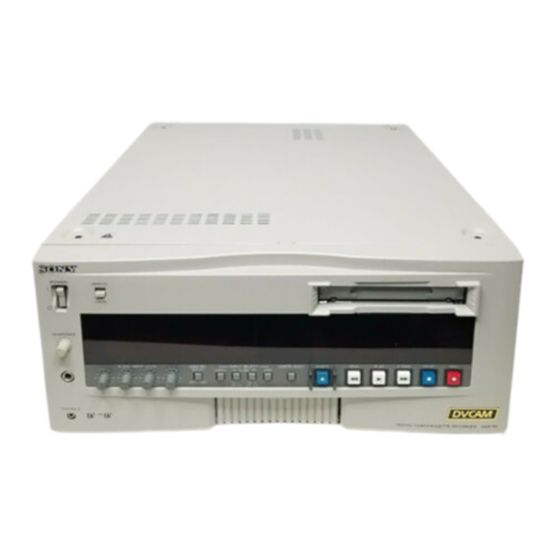
Sony DVCAM DSBK-130 Bedienungsanleitung
Time code input-output board
Verfügbare Sprachen
Verfügbare Sprachen
Quicklinks
Time Code
Input/Output Board
取扱説明書
2
ページ
Operating Instructions
Mode d'emploi
Bedienungsanleitung
Istruzioni per l'uso
お買い上げいただきありがとうございます。
電気製品は、安全のための注意事項を守らないと、火
警告
災や人身事故になることがあります。
• ご使用にあたっては、デジタルビデオカセットレコーダー本体に付
属の取扱説明書の「安全のために」と「
お読みください。お読みになったあとは、いつでも見られるところ
に必ず保管してください。
• 本基板の取り付けは、必ずお買い上げ店またはソニーのサービス窓
口にご依頼ください。
DSBK-130/130P
© 1996 by Sony Corporation
Page 9
Page 15
Seite 21
Pagina 27
3-858-534-04(1)
警告」 、 「
注意」をよく
J
EN
F
D
I

Verwandte Anleitungen für Sony DVCAM DSBK-130

Inhaltszusammenfassung für Sony DVCAM DSBK-130
- Seite 21 Deutsch Für Kunden in Deutschland Dieses Produkt kann im kommerziellen und in begrenztem Maße auch im industriellen Bereich eingesetzt werden. Dies ist eine Einrichtung, welche die Funk-Entstörung nach Klasse B besitzt. Inhaltsverzeichnis Kurzbeschreibung ............22 Installation ..............23...
- Seite 22 Die Time Code Input/Output Board DSBK-130P ist eine optionale Leiterplatte für den Einbau in einen DSR-85P/80P/ 60P oder einen anderen digitalen Videorecorder/Player von Sony. Die Installation dieser Leiterplatte ermöglicht die Ein- und Ausgabe von analogen Zeitcodesignalen (LTC) im EBU- Format.
- Seite 23 Installation Entfernen Sie die obere Abdeckung vom Videorecorder, und entfernen Sie die Leiterplattenhalterungen (1) und (2). Leiterplattenhalterung (1) Abdeckung Schraube Schraube Schraube Videorecorder Leiterplattenhalterung (2) Entfernen Sie die Leiterplatte aus dem DSR-85P bzw.die Leiterplatte SY-241 aus dem DSR-80P/60P. Von der Frontseite des Videorecorders/Players betrachtet sitzt die Leiterplatte SY-220/241 je nach Modell in dem nachfolgend aufgeführten Steckschlitzen.
- Seite 24 Installation Stecken Sie die Leiterplatte DSBK-130P fest auf die Leiterplatte SY-220/241. Für festen Steckanschluß sorgen, so daß bei DSBK-130P Leiterplatte Betrachtung in Leiterplatte Pfeilrichtung (A) kein SY-220/241 Zwischenraum verbleibt. Richtig: Falsch: Sichern Sie die DSBK-130P mit den zwei mitgelieferten Schrauben an der SY-220/241 festschrauben. Metallabdeckung der SY-220/241 Die weiß...
- Seite 25 Stecken Sie die Leiterplatte SY-220/241 wieder in ihren Steckschlitz im Videorecorder ein. Die Hebel nach unten drücken, und die Leiterplatte fest eindrücken. Bringen Sie die in Schritt 1 entfernten Leiterplattenhalterungen (1) und (2) wieder an, und schließen Sie wieder die Abdeckung des Videorecorder. Die Leiterplattenhalterung (1) verfügt über sieben Greiferpaare.
- Seite 27 Italiano Indice Presentazione ..............28 Installazione ..............29...