GE ATS1190 Montageanleitung
Smart card-leser
ATS1190
ATS1192
Smart Card Reader
I
NTRODUCTION
The ATS1190/1192 Smart Card Reader is a multifunction, all-
purpose proximity card reader suitable for all locations requiring a
short-range reader. The reader can be connected directly to the
ATS Control Panel (see figure
Menu system accessible via the BUS or by Configuration cards
programmed through Titan and the Smart Card Programmer
(ATS1621/22) or the ATS1481 Programming card.
The reader operates from 9 to 14 VDC. It has a quiescent current
consumption of less than 25 mA and less than 80 mA when
reading a card. The ATS1190 is supplied standard with a white
removable dress cover, which can be interchanged with one of
four other colours available.
The ATS1192 is a heavy-duty version designed for standard door
frames.
Both the ATS1190 & ATS1192 are waterproof.
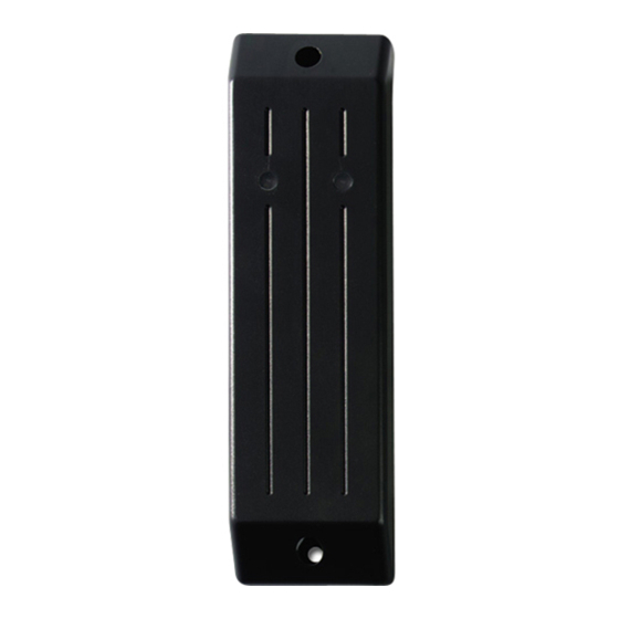
Figure
: Smart Card Reader
Blue LED:
Door open
Disarmed
M
OUNTING
The reader can be mounted on any flat surface by two pan head
screws, 3.0-3.5 mm diameter, located under the dress cover. A
slightly reduced range will be experienced when mounted on metal
surfaces. If mounting in an outdoor environment, ensure that the
blue LED is at the top.
It is not recommended to use countersunk screws.
For the ATS1190 the dress cover can be removed to expose the
mounting screw by gently prizing the sides away from the main
body to release the retaining clips and gently pulling on the
connection cord. Do not use excessive force or the reader can be
irreparably damaged.
After mounting, gently press the cover over the main body until it
locks into place.
ATS1190/1192 ATS1105 ATS1170 ATS2000/3000/4
Cable
Red
Black
Green
White
Yellow
Brown
Blue
Violet
). It is configurable through a
Red LED:
Door open
Armed
© 2005 GE Security B.V.
All rights reserved
000
J2
J1
J1
12V
12V
12V
0V
0V
0V
D0
D0
D-
D1
D1
D+
-
L2
-
-
L1
-
-
BZ
-
-
-
-
RAS
ADDRESSING
The address of the reader for BUS operations is set to the default
address RAS 16. Using a configuration card or accessing its on-
line Menu system when connected to the RS485 BUS can change
this. See the Programming Guide, Reader Address, for further
details.
T
AMPER
The reader is provided with a Tamper facility. When connected to
the BUS, Tamper data is transmitted to the Advisor Master with
system data. An external Open Collector output (violet wire) can
be configured as a Tamper control for both online and offline
operation.
R
EADER WIRING
Red:
Black:
0 Volts
Green:
D0 / D-
Clock
White:
D1/ D+
Data
Brown: LED 1
ATS1190/1192
Smart Card Reader
ATS1250/1260
Door 1, 2, 3, 4
12V
0V
D0
D1
L2
L1
BZ
With 4K7 (in series)
to Alarm Input 3
Positive 9 to 14 VDC supply
DC supply ground
RS485 Data - Wiegand Data 0
Absolute maximum, 12 V @ 10 mA
RS485 Data + Wiegand Data 1
Absolute maximum, 12 V @ 10 mA
Offline LED control configured to "Two Wire
Control" will control the red LED only
Wire grounded: Red LED on
Wire open: Red LED off
Wire at +5 V to +12 V: Red LED off or, offline
LED control configured to "One Wire Control"
will control both the red and blue LED's
Wire grounded: Blue LED on
Wire open circuit: Both LED's off
Wire at + 5 V to 12 V: Red LED on
Absolute maximum, 14 V
MAINST-ATS1190
ATS1250/1260
localbus
Comms
12V
0V
D-
D+
-
-
-
-
09/2005

Verwandte Anleitungen für GE ATS1190


Inhaltszusammenfassung für GE ATS1190
- Seite 1 It is not recommended to use countersunk screws. LED control configured to "One Wire Control" For the ATS1190 the dress cover can be removed to expose the will control both the red and blue LED’s mounting screw by gently prizing the sides away from the main...
-
Seite 2: Montage
Il est déconseillé d’utiliser des vis à tête fraisée. Entrée de demande de sortie lorsqu’en ligne Dans le cas du lecteur ATS1190 le capot peut être retiré afin vers Advisor Master. d’exposer les vis de montage en dégageant les bords du corps Cette entrée peut être connectée à... - Seite 3 Offline LED-regeling geconfigureerd als o.a. montage op standaard deurposten voor binnen en buiten “tweedraadsregeling” bestuurt alleen de rode toepassingen. LED. De ATS1190 & ATS1192 zijn beide uitgevoerd in een waterdichte Draad geaard: Rode LED aan. behuizing. Draad onderbroken: Rode LED uit Fig.
- Seite 4 - Drzwi otwarte PROWADZENIE - Rozbrojony Czerwona dioda LED: - Drzwi otwarte Inteligentny czytnik kart ATS1190/1192 jest wielofunkcyjnym, - Uzbrojony zbliżeniowym czytnikiem kart do powszechnego zastosowania, odpowiednim do wszelkich lokalizacji wymagających czytnika o ONTAŻ krótkim zasięgu. Czytnik moze byc podlaczony bezposrednio do centrali Advisor Master (zobacz rysunek ).
- Seite 5 O leitor opera a partir de 9 a 14 VDC. O seu consumo em standby puxando com cuidado o cabo de ligação. Não use força excessiva é inferior a 25mA e em leitura inferior a 80 mA. O ATS1190 é pois o leitor pode ficar irremediavelmente estragado.
- Seite 6 Leseren opererer fra 9 til 14 VDC. Den har et strømforbruk på mindre enn 25 mA i hviletilstand og mindre enn 80 mA under Rød: Positiv 9 til 14 VDC supply lesing av kort. ATS1190 kommer standard med et hvitt avtagbart Svart: 0 Volt Jord deksel, som kan byttes ut med en av de fire andre tilgjengelige Grønn: D0 / D-...
-
Seite 7: Montaje
Esta entrada puede conectarse a un pulsador simple conectado a tierra con sólo RTE Se puede retirar la cubierta de la unidad ATS1190 para acceder al seleccionado en la tarjeta de opción o en el tornillo de montaje forzando ligeramente los laterales hacia fuera Menú... - Seite 8 Läsaren drivs med 9 till 14 VDC. Den har en blygsam information finns i programmeringsmanualen (Läsaradress). strömförbrukning på mindre än 25 mA och mindre än 80 mA under läsning av kort. ATS1190 har ett vitt, avtagbart hölje som standard, ABOTAGE vilket kan bytas mot fyra andra tillgängliga färger.
- Seite 9 Der Leser kann mit 9 bis 14 V Gleichspannung betrieben werden. ESERVERKABELUNG Er hat eine Ruhestromaufnahme von weniger als 25 mA und Rot: +9 bis 14 V Gleichspannung benötigt zum Lesen einer Karte weniger als 80 mA. Der ATS1190 Schwarz: 0 Volt Spannungsversorgung wird standardmäßig mit einem weißen abnehmbaren Gehäuse geliefert, das durch ein Gehäuse in einer von vier...
- Seite 10 Maksimijännite 12 V @ 10 mA Lukijan käyttöjännite on 9 - 14 VDC. Sen virrankulutus lepotilassa Ruskea: LED 1 Offline-LED-ohjausmäärittely: on alle 25 mA ja korttia luettaessa alle 80 mA. ATS1190 “ ” Kaksijohdinohjaus ohjaa vain punaista toimitetaan valkoisella irrotettavalla kuorella. Laitteeseen on valoa.
- Seite 11 Dimensions (W x H x Dimensions (L x H x Afmetingen (B x H x Dimensioni (l × h × Wymiary zewnętrzne (SxWxG): 36mm x 110mm x ATS1190 ATS1190 20mm ATS1192 ATS1192 42mm x 150mm x 16mm Operating Température...