Werbung
Quicklinks
I N S T R U C T I O N S
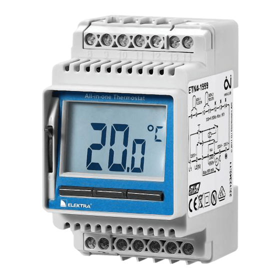
ETN4-1999
67152 01/12 (MBC)
• English
• Deutsch
• Русский
• Polish
English
The ETN4-1999 All-in-one is an electronic on/
off thermostat for 1 or 2 NTC sensors located
externally.
An All-in-one thermostat for many application
types:
• Electrical floor heating
• Frost protection
• Cooling
The thermostat should be DIN rail mounted.
A floor sensor is supplied.
WARNING – Important Safety Instructions.
Disconnect the power supply before carrying
out any installation or maintenance work on this
control unit and associated components. This
control unit and associated components should
only be installed by a competent person (i.e. a
qualified electrician). Electrical installation must
be in accordance with appropriate statutory
regulations.
NOTE: Use philips PH2 or slotted 4x0.8 mm
screwdriver. Screws must be tightened with a
torque of 0,5 Nm.
MOUNTING Of SENSORS
The 2 sensors contain a safety extra-low volt-
age (SELV) circuit, allowing the sensors to be
placed as close to the floor surface as neces-
sary without the risk of electric shock, should
the sensor cable become damaged. The two
wires from the sensor to the thermostat must be
separated from high voltage wires/cables.
The sensor cable may be extended up to 100
m by means of a separate two-core cable. The
two-core cable must be placed in a separate
pipe or segregated from power cables. Two
vacant wires in a multi-core cable used for
example to supply current to the floor heating
cable must not be used. The switching peaks of
such current supply lines may create interfer-
ence signals that prevent optimum controller
function. If a shielded cable is used, the shield
must not be connected to earth (PE).
floor sensor
It is recommended that the cable and sensor be
placed in a non-conductive installation pipe em-
bedded in the floor (fig. 2). The end of the pipe
must be sealed and the pipe placed as high as
possible in the concrete layer. Alternatively, the
sensor can be embedded directly in the floor.
The sensor cable must be led through a sepa-
rate pipe or segregated from power cables.
The floor sensor must be centred between the
heating cable.
Room sensor
The room sensor is used for comfort tempera-
ture regulation in rooms. The sensor should be
mounted on the wall approx. 1.6 m above the
floor in such a way as to allow free air circula-
tion around it. Draughts and direct sunlight or
other heat sources must be avoided (fig. 5).
INSTAllATION Of ThERMOSTAT
ETN4-1999 should be DIN rail mounted. The
mains, load and sensor cables should be con-
nected as shown in fig. 1+2.
To prevent loose cables from the fixed instal-
lation from coming into contact with the
terminal block for the floor sensor, they must be
restrained using cable ties.
NIGhT SETbACk / fROST pROTECTION
The ETN4-1999 has 2 inputs for night setback
and frost protection. See fig. 3+4. Do not use
night setback and frost protection at the same
time.
pOWER Up
To turn on the ETN4-1999 thermostat, push the
power slide button up to On "I". The backlit dis-
play will briefly show the application and then
the set temperature.
pROGRAMMING
See ETN4-1999 user manual.
fAUlT lOCATION
If the sensor is disconnected or short-circuited,
the heating system is switched off. The sensor
can be checked against the resistance table
(fig. 6).
ERROR COdES
E0: Internal error. The thermostat must be
replaced.
E1: External room sensor short-circuited or
disconnected (terminal 10-11).
E2: External floor sensor short-circuited or
disconnected (terminal 8-9).
E5: Overheating. The temperature is too high in
the thermostat and the heating is switched
off.
CERTIfCATION
VDE testet and certi-
fied.
CE marking.
According to the following standard:
LVD/EMC: EN 60730-2-9.
ClASSIfICATION
The product is a Class II device (enhanced
insulation) and must be connected in the follow-
ing way:
Term. 1:
Line (L) 230 V ±10%, 50/60 Hz
Term. 2:
Neutral (N)
Term. 3:
Output for control, max. 100mA
Term. 4–5:
Load, max. 16 A / 3600 W
Term. 6:
Input, night setback (S)*
Term. 7:
Input, frost protection (
Term. 8-9:
External floor sensor (SELV)
Term. 10-11: External room sensor (SELV)
Term. X:
Do not connect
* Do not use night setback and frost protection
at the same time.
ENvIRONMENT ANd RECYClING
Please help us to protect the environment by
disposing of the packaging in accordance with
national regulations for waste processing.
© 2012 OJ Electronics A/S
RECYClING Of ObSOlETE ApplIANCES
Appliances with this label must not
be disposed of with general
household waste. They must be
collected separately and disposed
of in compliance with local
regulations.
TEChNICAl dATA
Voltage .................... 230 VAC ±10% 50/60 Hz
Max. pre-fuse .............................................16 A
Built-in circuit breaker .................. 2-pole, 16 A
Output .............................. Max. 16 A / 3600 W
Control principle ............... ON/OFF or PWM/PI
Sensor type .... NTC (12kOhm) 3 m/max. 100 m
Control temperature range ............ -19.5/+70°C
Limit sensor ................................. -19.5/+70°C
Ambient operating temperature * ..... -20/+55°C
Night Setback relative ................... -19.5/+30°C
Night Setback regulator .......................0-100%
Frost protection, absolute ..................... 0-10°C
Frost protection regulator, relative ......0-100%
Control pollution degree ................................ 2
Rated impulse voltage .............................. 4 kV
Enclosure rating ....................................... IP 20
Automatic action .......................................... 1B
Dimensions ................ H/86, W/52,5, D/58 mm
DIN module size .....................................3xM36
Display ........ H/25, W/38 mm. segment backlit
* At very low ambient temperatues the display
may respond slowly.
The thermostat is maintenance free.
fIGURES
Located on page 2.
Fig. 1: ETN4-1999 terminal overview
Fig. 2: Application with floor and room sensor
Fig. 3: Night setback connection
Fig. 4: Frost protection connection
Fig. 5: Mounting room sensor
Fig: 6: Sensor resistance table
deutsch
Der ETN4-1999 ist ein elektronischer All-in-One
Thermostat für 1 oder 2 extern anbebrachte
NTC-Fühler.
Ein All-in-One Thermostat für viele Anwen-
dungsarten:
• Elektrische Fußbodenheizung
• Frostschutz
• Kühlung
Der Thermostat ist auf DIN-Schiene zu mon-
tieren.
Ein Bodenfühler wird mitgeliefert.
AChTUNG – Wichtige Sicherheitshinweise. Vor
der Ausführung von Installations- oder Instand-
haltungsarbeiten an dieser Regeleinheit und
zugehörigen Komponenten ist die Spannungs-
versorgung zu unterbrechen. Diese Regel-
einheit und zugehörige Komponenten dürfen
)*
nur von einer fachlich befähigten Person (d. h.
autorisierter Elektriker) installiert werden. Die
Elektroinstallation muss in Übereinstimmung
mit den neuesten EU-Richtlinien für elektri-
sche Betriebsmittel und den diesbezüglichen
Rechtsvorschriften erfolgen.
hINWEIS: Bitte Philips-PH2- oder 4×0,8 mm
Schlitzschraubendreher verwenden. Schrauben
müssen mit einem Moment von 0,5 Nm festge-
schraubt werden.
1
Werbung

Verwandte Anleitungen für ELEKTRA ETN4-1999

Inhaltszusammenfassung für ELEKTRA ETN4-1999
- Seite 1 Limit sensor ......... -19.5/+70°C NIGhT SETbACk / fROST pROTECTION Ambient operating temperature * ..-20/+55°C English The ETN4-1999 has 2 inputs for night setback Night Setback relative ....-19.5/+30°C and frost protection. See fig. 3+4. Do not use Night Setback regulator .......0-100% night setback and frost protection at the same Frost protection, absolute .....
-
Seite 2: Установка Термостата
Электронный термостат Вкл./Выкл. «Все НОЧНОЕ ПОНИЖЕНИЕ ТЕМПЕРАТУРЫ / unterbrochen (Klemme 8-9). ПРЕДОТВРАЩЕНИЕ ЗАМЕРЗАНИЯ в одном» ETN4-1999 для одного или двух E5: Überhitzung. Die Temperatur im Thermostat выносных датчиков типа NTC. ETN4-1999 имеет 2 входа для сигналов ist zu hoch und die Heizung ist ausgeschal- Термостат... - Seite 3 Рис. 2: Использование с датчиками отключился. температуры пола и воздуха NIEM Рис. 3: Режим ночного понижения Regulator ETN4-1999 ma dwa wejścia. Jedno CEpTИФИkAlЦИИ температуры dla obniżenia lub podwyższenia temperatury a Рис. 4: Режим предотвращения замерзания drugie dla ochrony przed zamarzaniem, patrz VDE и...
-
Seite 4: Dane Techniczne
..........001101349-0001/2 * Przy bardzo niskich temperaturach zewnętrz- nych, wyświetlacz może mieć spowolniony czas reakcji. Regulator jest urządzeniem bezobsługowym. RYSUNKI (str. 2) rys. 1: ETN4-1999 widok ogólny regulatora rys. 2: Zastosowanie z czujnikiem temperatury podłogi i powietrza w pomieszczeniu rys. 3: Aktywacja funkcji obniżenia lub pod- wyższenia temperatury rys. 4:... - Seite 5 Fig.1 Fig.2 Fig.3 Fig.4 Fig.5 Fig. 6 ROOM SENSOR Sensor Temp.(˚C) Value (ohm) 64000 38000 23300 14800 9700 © 2012 OJ Electronics A/S...
- Seite 6 © 2012 OJ Electronics A/S...
- Seite 7 © 2012 OJ Electronics A/S...
- Seite 8 ElEkTRA ul. Marynarska 14 02-674 Warszawa · Poland Tel. (+48 22) 843 32 82 office@elektra.eu · www.elektra.eu The trademark is registered and belongs to OJ Electronics A/S · © 2012 OJ Electronics A/S...