Inhaltsverzeichnis
Werbung
Verfügbare Sprachen
Verfügbare Sprachen
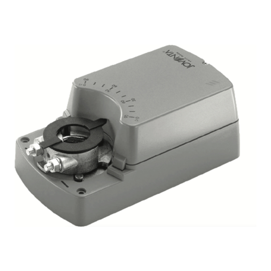
DAS / DA / DAL
2-Point ON/OFF and 3-Point Floating Actuators
Installation Guide
English ....................................1
Français ..................................6
Deutsch ................................. 11
Italiano...................................16
Español ................................21
Nederlandse..........................26
Svenska ................................31
Česky ....................................36
P/N 14-88360-1823 Rev. B
Issue Date 10 2007
Werbung
Inhaltsverzeichnis

Verwandte Anleitungen für JOVENTA DAS series


Inhaltszusammenfassung für JOVENTA DAS series
- Seite 1 DAS / DA / DAL 2-Point ON/OFF and 3-Point Floating Actuators Installation Guide P/N 14-88360-1823 Rev. B Issue Date 10 2007 English ........1 Français ........6 Deutsch ......... 11 Italiano........16 Español ........21 Nederlandse......26 Svenska ........31 Česky ........36...
- Seite 2 Figure 1: Dimensions in mm (inches)
- Seite 3 Figure 2: Actuator Open...
- Seite 4 Figure 3: Mounting Instructions...
- Seite 5 Figure 4: ON/OFF and Floating Figure 5: Parallel connection Control Figure 6: Auxiliary switches Figure 7: Potentiometer...
-
Seite 6: General Features
DAS / DA / DAL 2-Point ON/OFF and 3-Point Floating Actuators Installation Guide P/N 14-88360-1823 Rev. B Issue Date 10 2007 READ THIS INSTRUCTION SHEET AND THE SAFETY WARNINGS CAREFULLY BEFORE INSTALLING AND SAVE IT FOR FUTURE USE General Features The actuators are intended for the operation of air dampers in HVAC systems. -
Seite 7: Installation And Adjustment
Installation and adjustment Figure 3: Mounting Instructions Installation Attach the actuator to the damper spindle by means of the adapter and secure the locking device with the screws provided. Angle of rotation limiting An angle-of-rotation/working range (Figure 2 f1.) of less than 90° can be limited mechanically by repositioning the adapter in 5°... -
Seite 8: Wiring Diagrams
Wiring Diagrams Figure 4: ON/OFF and Floating Control (1) ON/OFF (2) Floating Figure 5: Parallel connection (1) ON/OFF (2) Floating Figure 6: Auxiliary switches (1) Auxiliary switch factory set at 10° CW (2) Auxiliary switch factory set at 80° CW (3) Actuator at 0°position Figure 7: Potentiometer... -
Seite 9: Ordering Codes
Auxiliary switches adjustment (See Figure 2 a. - b.) Example: Switching position adjustment a. to 30° and b. to 70°. 30°: Depress the manual button (Figure 2 d.) and rotate the adapter (Figure 2 e.) to the 30° position. Slightly loosen the Phillips screw in the cam wheel a. so that the wheel can be moved by hand. -
Seite 10: Technical Specifications
Technical Specifications Actuators DAS1 DAL1 DAS2 DAL2 Drive torque 8 Nm 16 Nm 24 Nm 8 Nm 16 Nm 24 Nm Damper area 1.5 m 3.0 m 4.5 m 1.5 m 3.0 m 4.5 m Running time 30 s 80 s 125 s 30 s 80 s... -
Seite 11: Funzioni Generali
DAS / DA / DAL Attuatori modulanti 3 punti e ON/OFF 2 punti Guida installazione P/N 14-88360-1823 Rev. B Data di pubblicazione 10 2007 LEGGERE ATTENTAMENTE QUESTE ISTRUZIONI E LE AVVERTENZE PRIMA DELL'INSTALLAZIONE E CONSERVARLE PER USO FUTURO Funzioni generali Gli attuatori sono progettati per il funzionamento delle serrande nei sistemi HVAC (Heating, Ventilation and Air Conditioning). -
Seite 12: Installazione E Regolazione
Installazione e regolazione Figura 3: Istruzioni per il montaggio Installazione Collegare l'attuatore al perno della serranda mediante l'adattatore e fissare il dispositivo di bloccaggio con le viti fornite. Limitazione dell'angolo di rotazione È possibile limitare meccanicamente l'angolo di rotazione/intervallo di funzionamento (figura 2 f1.) su un valore inferiore a 90°... - Seite 13 Schemi di cablaggio Figura 4: Controllo ON/OFF e modulante (1) ON/OFF (2) Modulante Figura 5: Connessione parallela (1) ON/OFF (2) Modulante Figura 6: Interruttori ausiliari (1) Impostazione predefinita interruttore ausiliario: 10° CW (2) Impostazione predefinita interruttore ausiliario: 80° CW (3) Attuatore nella posizione 0° Figura 7: Potenziometro Connessioni elettriche tramite trasformatore di...
- Seite 14 Regolazione degli interruttori ausiliari (vedere le figure 2 a. - b.) Esempio: regolazione della posizione di commutazione a. su 30° e b. su 70°. 30°: spingere il pulsante manuale (figura 2 d.) e ruotare l'adattatore (figura 2 e.) nella posizione 30°. Allentare leggermente la vite con testa a croce nell'eccentrico a.
-
Seite 15: Specifiche Tecniche
Specifiche tecniche Attuatori DAS1 DAL1 DAS2 DAL2 Coppia 8 Nm 16 Nm 24 Nm 8 Nm 16 Nm 24 Nm Sup. serranda 1,5 m 3,0 m 4,5 m 1,5 m 3,0 m 4,5 m Tempo di esecuzione 30 s 80 s 125 s 30 s 80 s... -
Seite 16: Caractéristiques Générales
DAS / DA / DAL Commandes de marche/arrêt à 2 points et commandes flottantes à 3 points Manuel d’installation P/N 14-88360-1823 Rév. B Issue Date 10 2007 LISEZ ATTENTIVEMENT LES PRÉSENTES INSTRUCTIONS ET LES CONSIGNES DE SÉCURITÉ AVANT DE PROCÉDER À L'INSTALLATION ET CONSERVEZ-LES AUX FINS D’UTILISATION ULTÉRIEURE Caractéristiques générales... -
Seite 17: Installation Et Réglage
Installation et réglage Figure 3: Instructions de montage Installation Fixez la commande à l’axe du clapet à l’aide de l’adaptateur et le dispositif de verrouillage à l’aide des vis fournies. Limitation de l’angle de rotation Il est possible de limiter mécaniquement la plage d’angle de rotation/ fonctionnement (figure 2 f1.) à... -
Seite 18: Schémas De Câblage
Schémas de câblage Figure 4: Commande de marche/arrêt et commande flottante (1) Marche/arrêt (2) Flottante Figure 5: Branchement en parallèle (1) Marche/arrêt (2) FlottanteCommutateurs auxiliaires (3) Commutateur auxiliaire réglé en usine à 10° (sens horaire) (4) Commutateur auxiliaire réglé en usine à 80° (sens horaire) (5) Commande en position 0°... - Seite 19 Réglage des commutateurs auxiliaires (voir la figure 2 a. - b.) Exemple : Réglage de la position des commutateurs a. à 30° et b. à 70°. 30°: Appuyez sur le bouton manuel (figure 2 d.) et faites tourner l’adaptateur (figure 2 e.) jusqu'à la position 30°. Desserrez légèrement la vis cruciforme de la roue à...
-
Seite 20: Caractéristiques Techniques
Caractéristiques techniques Commandes DAS1 DAL1 DAS2 DAL2 Couple moteur 8 Nm 16 Nm 24 Nm 8 Nm 16 Nm 24 Nm Surface du clapet 1,5 m 3,0 m 4,5 m 1,5 m 3,0 m 4,5 m Temps de fonctionnement 30 s 80 s 125 s 30 s... -
Seite 21: Allgemeine Merkmale
DAS / DA / DAL 2-Punkt AUF/ZU und 3-Punkt Stellantriebe Installationsanleitung P/N 14-88360-1823 Rev. B Ausgabedatum 10 2007 LESEN SIE DIESE ANLEITUNG UND DIE SICHERHEITSHINWEISE VOR DER INSTALLATION SORGFÄLTIG DURCH UND BEWAHREN SIE SIE FÜR SPÄTERE REFERENZZWECKE AUF Allgemeine Merkmale Die Stellantriebe sind für die Verstellung von Luftklappen in Lüftungs- und Klimaanlagen entwickelt worden. -
Seite 22: Installation Und Einstellung
Installation und Einstellung Abbildung 3: Montageanweisungen Installation Bringen Sie den Stellantrieb mit Hilfe des Adapters an der Klappenachse an und befestigen Sie den Steck-Schraubklemmen-Anschluss mit den mitgelieferten Schrauben. Drehwinkel-Begrenzung Ein Drehwinkel/Arbeitsbereich (Abbildung 2 f1.) von unter 90° kann, entsprechend der Anforderungen, mechanisch durch Umstecken des Adapters in 5°-Schritten begrenzt werden. -
Seite 23: Elektrische Anschlüsse Über Sicherheitstransformator
Anschlusspläne Abbildung 4: AUF/ZU und 3-Punkt-Ansteuerung (1) AUF/ZU (2) 3-Punkt Abbildung 5: Parallelanschluss (1) AUF/ZU (2) 3-Punk Abbildung 6: Hilfsschalter (1) Werkseitige Hilfsschalter-Einstellung auf 10° (CW) (2) Werkseitige Hilfsschalter-Einstellung auf 80° (CW) (3) Stellantrieb auf 0°-Stellung Abbildung 7: Potentiometer Elektrische Anschlüsse über Sicherheitstransformator •... -
Seite 24: Hilfsschalter-Einstellung (Siehe Abbildung 2 A. - B.)
Hilfsschalter-Einstellung (siehe Abbildung 2 a. - b.) Beispiel: Schaltpositions-Einstellung a. auf 30° und b. auf 70°. 30°: Drücken Sie die Handtaste (Abbildung 2 d.) und drehen Sie den Adapter (Abbildung 2 e.) in die 30°-Stellung. Lösen Sie die Phillips-Schraube des Schaltrades etwas, a. -
Seite 25: Technische Daten
Technische Daten Stellantriebe DAS1 DAL1 DAS2 DAL2 Drehmoment 8 Nm 16 Nm 24 Nm 8 Nm 16 Nm 24 Nm Klappenfläche 1,5 m 3,0 m 4,5 m 1,5 m 3,0 m 4,5 m Laufzeit 30 s 80 s 125 s 30 s 80 s 125 s... -
Seite 26: Características Generales
DAS / DA / DAL Actuadores ON/OFF de 2 puntos y actuadores flotantes de 3 puntos P/N 14-88360-1823 Rev. B Guía de instalación Fecha de publicaciуn 10 2007 ANTES DE LA INSTALACIÓN, LEA CUIDADOSAMENTE ESTAS INSTRUCCIONES Y LAS ADVERTENCIAS DE SEGURIDAD Y CONSÉRVELAS PARA SU USO FUTURO Características generales Los actuadores intervienen en el funcionamiento de los reguladores de aire... -
Seite 27: Instalación Y Ajuste
Instalación y ajuste Figura 3: Instrucciones de montaje Instalación Sujete el actuador al eje del regulador mediante el adaptador y asegure el dispositivo de bloqueo con los pernos que se suministran. Limitación del ángulo de rotación Para limitar de forma mecánica un ángulo de rotación o una gama de trabajo (Figura 2 f1.) inferior a 90°, deberá... - Seite 28 Diagramas del cableado Figura 4: Control ON/OFF y flotante (1) ON/OFF (2) Flotante Figura 5: Conexión en paralelo (1) ON/OFF (2) Flotante Figura 6: Interruptores auxiliares (1) Interruptor auxiliar, ajustado de fábrica a 10° CW (2) Interruptor auxiliar, ajustado de fábrica a 80° CW (3) Actuador en la posición 0°...
- Seite 29 Ajuste de los interruptores auxiliares (Véase la figura 2 a. - b.) Ejemplo: Ajuste de la posición de interruptores a. a 30° y b. a 70°. 30°: Pulse el botón manual (Figura 2 d.) y gire el adaptador (Figura 2 e.) hasta la posición de 30°.
-
Seite 30: Especificaciones Técnicas
Especificaciones técnicas Actuadores DAS1 DAL1 DAS2 DAL2 Torque de dirección 8 Nm 16 Nm 24 Nm 8 Nm 16 Nm 24 Nm Área del regulador 1,5 m 3,0 m 4,5 m 1,5 m 3,0 m 4,5 m Tiempo de ejecución 30 s 80 s 125 s... -
Seite 31: Installatiehandleiding
DAS / DA / DAL Bekrachtigers met 2 punten AAN/UIT en 3 punten variabel Onderdeelnr. 14-88360-1823 Rev. B Installatiehandleiding Uitgiftedatum 10 2007 LEES DIT INSTRUCTIEBLAD EN DE VEILIGHEIDSWAARSCHUWINGEN ZORGVULDIG VOORDAT DE INSTALLATIE WORDT UITGEVOERD, EN BEWAAR DIT MATERIAAL ZODAT U HET IN DE TOEKOMST OOK NOG KUNT RAADPLEGEN Algemene functies De bekrachtigers zijn bedoeld voor luchtdempers in HVAC-systemen. -
Seite 32: Installatie En Afstelling
Installatie en afstelling Figuur 3: Montage-instructies Installatie Bevestig de bekrachtiger op de demperas door middel van de adapter en zet de vergrendeling met de meegeleverde schroeven vast. Draaihoek begrenzend Een draaihoek/werkbereik (figuur 2 f1.) van minder dan 90° kan mechanisch worden begrensd door de adapter naar behoefte in stappen van 5°... -
Seite 33: Elektrische Aansluitingen Via Isolerende Veiligheidstransformator
Bedradingsschema's Figuur 4: AAN/UIT en variabele regeling (1) AAN/UIT (2) Variabel Figuur 5: Parallelle aansluiting (1) AAN/UIT (2) Variabel Figuur 6: AUX-schakelaars (1) Fabrieksinstelling van AUX-schakelaar 10° rechtsom (2) Fabrieksinstelling van AUX-schakelaar 80° rechtsom (3) Bekrachtiger op positie 0° Figuur 7: Potentiometer Elektrische aansluitingen via isolerende veiligheidstransformator •... - Seite 34 Afstelling van AUX-schakelaars (zie figuur 2 a. - b.) Voorbeeld: Schakelaarpositie a. op 30° en b. op 70°. 30°: Druk de knop voor handmatig in (figuur 2 d.) en draai de adapter (figuur 2 e.) naar de positie voor 30°. Draai de kruiskopschroef in het nokwiel a. iets los zodat het wiel handmatig kan worden bewogen.
-
Seite 35: Technische Specificaties
Technische specificaties Bekrachtigers DAS1 DAL1 DAS2 DAL2 Aandrijfmoment 8 Nm 16 Nm 24 Nm 8 Nm 16 Nm 24 Nm Dempergebied 1,5 m 3,0 m 4,5 m 1,5 m 3,0 m 4,5 m Looptijd 30 s 80 s 125 s 30 s 80 s 125 s... -
Seite 36: Installationsguide
DAS / DA / DAL 2-punkts PÅ/AV och 3-punkts flytande ställdon Installationsguide P/N 14-88360-1823 ver. B Utgivningsdatum 10 2007 LÄS DET HÄR INSTRUKTIONSBLADET OCH SÄKERHETSANVISNINGARNA NOGGRANT INNAN DU INSTALLERAR MODULEN OCH SPARA DEM FÖR FRAMTIDA BRUK Allmänna funktioner Ställdonen är avsedda att styra luftfuktare i HVAC-system. Den universella adaptern gör att ställdonen kan monteras direkt på... - Seite 37 Installation och justering Figur 3: Monteringsinstruktioner Installation Fäst ställdonet vid fuktarspindeln med hjälp av adaptern och skruva fast låsenheten med de medföljande skruvarna. Vinkel för roteringsbegränsning En roteringsvinkel eller ett driftområde (figur 2 f1.) som är mindre än 90° kan begränsas mekaniskt genom att adaptern flyttas i steg om 5° efter behov.
- Seite 38 Illustration kabeldragning Figur 4: PÅ/AV och flytande kontroll (1) PÅ/AV (2) Flytande Figur 5: Parallellanslutning (1) PÅ/AV (2) Flytande Figur 6: Extra brytare (1) Extra brytare med fabriksinställningen 10° (medsols) (2) Extra brytare med fabriksinställningen 80° (medsols) (3) Ställdonet i positionen 0° Figur 7: Kompensator Elektriska anslutningar via transformator för...
- Seite 39 Justering av extra brytare (se figur 2 a. – b.) Exempel: Växla positionsjusteringen a. till 30° och b. till 70°. 30°: Tryck ned den manuella knappen (figur 2 d.) och rotera adaptern (figur 2 e.) till positionen 30°. Lossa stjärnskruven i kamhjulet något a. så att hjulet kan flyttas för hand.
-
Seite 40: Tekniska Specifikationer
Tekniska specifikationer Ställdon DAS1 DAL1 DAS2 DAL2 Drivmoment 8 Nm 16 Nm 24 Nm 8 Nm 16 Nm 24 Nm Fuktarområde 1,5 m 3,0 m 4,5 m 1,5 m 3,0 m 4,5 m Drifttid 30 s 80 s 125 s 30 s 80 s 125 s... -
Seite 41: Obecné Funkce
DAS / DA / DAL Dvoubodové spínací a tříbodové tlumené spouštěče Č. 14-88360-1823 Rev. B Instalační příručka Datum vydání 10 2007 PŘED INSTALACÍ SI POZORNĚ PŘEČTĚTE TYTO POKYNY A BEZPEČNOSTNÍ VAROVÁNÍ A USCHOVEJTE JE PRO POZDĚJŠÍ POUŽITÍ Obecné funkce Spouštěče jsou určeny pro řízení regulačních vzduchových ventilů v klimatizačních systémech. -
Seite 42: Instalace A Nastavení
Instalace a nastavení Obrázek 3: Montážní pokynyb Instalace Připevněte pomocí adaptéru spouštěč k hřídeli ventilu a zajistěte pojistný mechanismus pomocí dodávaných šroubů. Omezení úhlu otočení Úhel otočení nebo pracovní rozsah (obrázek 2 f1.) v úhlu menším než 90° mohou být podle potřeby omezeny mechanicky změnou polohy adaptéru v krocích po 5°. -
Seite 43: Schémata Zapojení
Schémata zapojení Obrázek 4: Zapnutí a vypnutí a řízení tlumení (1) Zapnutí a vypnutí (2) Tlumení Obrázek 5: Paralelní zapojení (1) Zapnutí a vypnutí (2) Tlumení Obrázek 6: Pomocné spínače (1) Pomocný spínač je továrně nastaven na 10° (doprava) (2) Pomocný spínač je továrně nastaven na 80° (doprava) (3) Spouštěč... - Seite 44 Nastavení pomocných spínačů (viz obrázek 2 a. – b.) Příklad: Nastavení spínací polohy a. nejvýše 30° a b. nejvýše 70°. 30°: Stiskněte manuální tlačítko (obrázek 2 d.) a otočte adaptér (obrázek 2 e.) do polohy 30°. Mírně povolte křížový šroub vačkového kola a., aby bylo možné kolem pohybovat ručně.
-
Seite 45: Technické Údaje
Technické údaje Spouštìèe DAS1 DAL1 DAS2 DAL2 Krouticí moment 8 Nm 16 Nm 24 Nm 8 Nm 16 Nm 24 Nm motoru Plocha ventilu 1,5 m 3,0 m 4,5 m 1,5 m 3,0 m 4,5 m Provozní doba 30 s 80 s 125 s 30 s... - Seite 46 DAS / DA / DAL Published in Italy Installation Guide...