Herunterladen Inhalt Inhalt Diese Seite drucken

Werbung

Verfügbare Sprachen
  • DE

Verfügbare Sprachen

  • DEUTSCH, seite 50
Version 1.0
Published June 2019
Copyright©2019 ASRock INC. All rights reserved.
Copyright Notice:
No part of this documentation may be reproduced, transcribed, transmitted, or
translated in any language, in any form or by any means, except duplication of
documentation by the purchaser for backup purpose, without written consent of
ASRock Inc.
Products and corporate names appearing in this documentation may or may not
be registered trademarks or copyrights of their respective companies, and are used
only for identification or explanation and to the owners' benefit, without intent to
infringe.
Disclaimer:
Specifications and information contained in this documentation are furnished for
informational use only and subject to change without notice, and should not be
constructed as a commitment by ASRock. ASRock assumes no responsibility for
any errors or omissions that may appear in this documentation.
With respect to the contents of this documentation, ASRock does not provide
warranty of any kind, either expressed or implied, including but not limited to
the implied warranties or conditions of merchantability or fitness for a particular
purpose.
In no event shall ASRock, its directors, officers, employees, or agents be liable for
any indirect, special, incidental, or consequential damages (including damages for
loss of profits, loss of business, loss of data, interruption of business and the like),
even if ASRock has been advised of the possibility of such damages arising from any
defect or error in the documentation or product.
This device complies with Part 15 of the FCC Rules. Operation is subject to the following
two conditions:
(1) this device may not cause harmful interference, and
(2) this device must accept any interference received, including interference that
may cause undesired operation.
CALIFORNIA, USA ONLY
The Lithium battery adopted on this motherboard contains Perchlorate, a toxic substance
controlled in Perchlorate Best Management Practices (BMP) regulations passed by the
California Legislature. When you discard the Lithium battery in California, USA, please
follow the related regulations in advance.
"Perchlorate Material-special handling may apply, see www.dtsc.ca.gov/hazardouswaste/
perchlorate"
ASRock Website: http://www.asrock.com

Werbung

Inhaltsverzeichnis
loading

Inhaltszusammenfassung für ASROCK X570 Extreme4

  • Seite 1 (including damages for loss of profits, loss of business, loss of data, interruption of business and the like), even if ASRock has been advised of the possibility of such damages arising from any defect or error in the documentation or product.
  • Seite 2 If you require assistance please call ASRock Tel : +886-2-28965588 ext.123 (Standard International call charges apply) The terms HDMI®...
  • Seite 3: Motherboard-Layout

    X570 Extreme4 Motherboard Layout AMD_FAN_LED1 CPU_FAN2/WP ATX12V1 ATX12V2 CPU_FAN1 USB 3.2 Gen1 T: USB3 B: USB4 USB 3.2 Gen2 T: USB31_TA_1 B: USB31_TC_1 USB 3.2 Gen1 Top: T: USB5 RJ-45 B: USB6 CHA_FAN1/WP USB_5 SPI_TPM_J1 BIOS PCIE1 CHA_FAN4/WP PCIE2 Premium...
  • Seite 4 No. Description 8 pin 12V Power Connector (ATX12V1) 4 pin 12V Power Connector (ATX12V2) CPU Fan Connector (CPU_FAN1) CPU / Waterpump Fan Connector (CPU_FAN2/WP) 2 x 288-pin DDR4 DIMM Slots (DDR4_A1, DDR4_B1) 2 x 288-pin DDR4 DIMM Slots (DDR4_A2, DDR4_B2) AMD FAN LED Header (AMD_FAN_LED1) ATX Power Connector (ATXPWR1) USB 3.2 Gen1 Header (USB3_9_10)
  • Seite 5 X570 Extreme4 I/O Panel No. Description No. Description PS/2 Mouse/Keyboard Port Antenna Bracket (on I/O Panel Shield) LAN RJ-45 Port* USB 3.2 Gen1 Ports (USB3_56)*** Central / Bass (Orange) USB 3.2 Gen2 Type-A Port (USB31_TA_1) Rear Speaker (Black) USB 3.2 Gen2 Type-C Port (USB31_TC_1) Line In (Light Blue) USB 3.2 Gen1 Ports (USB3_34)
  • Seite 6 * There are two LEDs on each LAN port. Please refer to the table below for the LAN port LED indications. ACT/LINK LED SPEED LED LAN Port Activity / Link LED Speed LED Status Description Status Description No Link 10Mbps connection Blinking Data Activity Orange...
  • Seite 7 X570 Extreme4 ** If you use a 2-channel speaker, please connect the speaker’s plug into “Front Speaker Jack”. See the table below for connection details in accordance with the type of speaker you use. Audio Output Front Speaker Rear Speaker...
  • Seite 8: Chapter 1 Introduction

    If you require technical support related to this mother- board, please visit our website for specific information about the model you are using. You may find the latest VGA cards and CPU support list on ASRock’s website as well. ASRock website http://www.asrock.com.
  • Seite 9: Specifications

    * For Ryzen Series CPUs (Picasso), ECC is only supported with PRO CPUs. * Please refer to Memory Support List on ASRock’s website for more information. (http://www.asrock.com/) * Please refer to page 25 for DDR4 UDIMM maximum frequency support.
  • Seite 10 AMD Ryzen series CPUs (Pinnacle Ridge) • 2 x PCI Express 3.0 x16 Slots (single at x16 (PCIE1); dual at x16 (PCIE1) / x4 (PCIE4))* AMD Ryzen series CPUs (Picasso) • 2 x PCI Express 3.0 x16 Slots (single at x8 (PCIE1); dual at x8 (PCIE1) / x4 (PCIE4))* * Supports NVMe SSD as boot disks • 3 x PCI Express 4.0 x1 Slots...
  • Seite 11 Pinnacle Ridge and Picasso)* • 1 x Hyper M.2 Socket (M2_2), supports M Key type 2230/2242/2260/2280/22110 M.2 SATA3 6.0 Gb/s module and M.2 PCI Express module up to Gen4x4 (64 Gb/s)* * Supports NVMe SSD as boot disks * Supports ASRock U.2 Kit...
  • Seite 12 • 1 x Front Panel Audio Connector (15μ Gold Audio Connector) • 1 x AMD LED Fan USB Header • 1 x Thunderbolt AIC Connector (5-pin) (Supports ASRock Thunderbolt AIC Card only) • 2 x USB 2.0 Headers (Support 4 USB 2.0 ports) (Supports...
  • Seite 13 X570 Extreme4 • 2 x USB 3.2 Gen1 Headers (Support 4 USB 3.2 Gen1 ports) (Supports ESD Protection) • 1 x Front Panel Type C USB 3.2 Gen1 Header (Supports ESD Protection) BIOS • AMI UEFI Legal BIOS with GUI support Feature • Supports “Plug and Play”...
  • Seite 14 * For detailed product information, please visit our website: http://www.asrock.com Please realize that there is a certain risk involved with overclocking, including adjusting the setting in the BIOS, applying Untied Overclocking Technology, or using third-party overclocking tools. Overclocking may affect your system’s stability, or even cause damage to the components and devices of your system.
  • Seite 15: Chapter 2 Installation

    X570 Extreme4 Chapter 2 Installation This is an ATX form factor motherboard. Before you install the motherboard, study the configuration of your chassis to ensure that the motherboard fits into it. Pre-installation Precautions Take note of the following precautions before you install motherboard components or change any motherboard settings.
  • Seite 16: Installing The Cpu

    2.1 Installing the CPU Unplug all power cables before installing the CPU.
  • Seite 17 X570 Extreme4...
  • Seite 18 2.2 Installing the CPU Fan and Heatsink After you install the CPU into this motherboard, it is necessary to install a larger heatsink and cooling fan to dissipate heat. You also need to spray thermal grease between the CPU and the heatsink to improve heat dissipation. Make sure that the CPU and the heatsink are securely fastened and in good contact with each other.
  • Seite 19 X570 Extreme4...
  • Seite 20 Installing the AM4 Box Cooler SR2...
  • Seite 21 X570 Extreme4...
  • Seite 22 4-pin FAN cable RGB LED Cable +12V *The diagrams shown here are for reference only. The headers might be in a different position on your motherboard. Please refer to page 35 for the orientation of AMD Fan LED Header (AMD_ FAN_LED1).
  • Seite 23 X570 Extreme4 Installing the AM4 Box Cooler SR3...
  • Seite 25 X570 Extreme4...
  • Seite 26 +12V Please note that only one cable should be used at a time in this step. If you select AMD_FAN_LED1, please install ASRock utility "ASRock Polychrome SYNC". If you select USB connector, please install AMD utility "SR3 Settings Software". *The diagrams shown here are for reference only. The headers might be in a different position on your motherboard.
  • Seite 27 X570 Extreme4 2.3 Installing Memory Modules (DIMM) This motherboard provides four 288-pin DDR4 (Double Data Rate 4) DIMM slots, and supports Dual Channel Memory Technology. 1. For dual channel configuration, you always need to install identical (the same brand, speed, size and chip-type) DDR4 DIMM pairs.
  • Seite 28 Ryzen Series CPUs (Picasso): UDIMM/SO-DIMMs Memory Slot # of DIMMs on # of Ranks 1.20V the Channel per DIMM SR: 2933 1 of 1 DR: 2677 SR: 2667 1 of 2 xR-0 DR: 2400 2 of 2 1R-1R 2133 2 of 2 2R-xR 1866 x=1 or 2...
  • Seite 29 X570 Extreme4 The DIMM only fits in one correct orientation. It will cause permanent damage to the motherboard and the DIMM if you force the DIMM into the slot at incorrect orientation.
  • Seite 30 2.4 Expansion Slots (PCI Express Slots) There are 5 PCI Express slots on the motherboard. Before installing an expansion card, please make sure that the power supply is switched off or the power cord is unplugged. Please read the documentation of the expansion card and make necessary hardware settings for the card before you start the installation.
  • Seite 31 X570 Extreme4 2.5 Jumpers Setup The illustration shows how jumpers are setup. When the jumper cap is placed on the pins, the jumper is “Short”. If no jumper cap is placed on the pins, the jumper is “Open”. Clear CMOS Jumper...
  • Seite 32 2.6 Onboard Headers and Connectors Onboard headers and connectors are NOT jumpers. Do NOT place jumper caps over these headers and connectors. Placing jumper caps over the headers and connectors will cause permanent damage to the motherboard. System Panel Header Connect the power PLED+ PLED-...
  • Seite 33 X570 Extreme4 Power LED and Speaker Please connect the SPEAKER DUMMY Header chassis power LED and DUMMY (7-pin SPK_PLED1) the chassis speaker to this (see p.1, No. 19) header. PLED+ PLED+ PLED- Serial ATA3 Connectors These eight SATA3 (SATA3_1_2: connectors support SATA see p.1, No.
  • Seite 34 Front Panel Type C USB There is one Front 3.2 Gen1 Header Panel Type C USB 3.2 (26-pin F_USB31_TC_1) Gen1 Header on this (see p.1, No. 17) motherboard. This header is used for connecting a USB 3.2 Gen1 module for USB Type-C Cable additional USB 3.2 Gen1 ports.
  • Seite 35 X570 Extreme4 (4-pin CHA_FAN4/WP) FAN_VOLTAGE (see p.1, No. 12) CHA_FAN_SPEED FAN_SPEED_CONTROL CPU Fan Connector This motherboard pro- FAN_SPEED_CONTROL CPU_FAN_SPEED (4-pin CPU_FAN1) vides a 4-Pin CPU fan FAN_VOLTAGE (see p.1, No. 3) (Quiet Fan) connector. If you plan to connect a 3-Pin CPU fan, please connect it to Pin 1-3.
  • Seite 36 ATX 12V Power Please connect an ATX Connector 12V power supply to this (4-pin ATX12V2) connector. (see p.1, No. 2) *The power supply plug fits into this connector in only one orientation. Thunderbolt AIC Please connect a Thunderbolt™ Connector add-in card (AIC) to the (5-pin TB1) Thunderbolt AIC connector via (see p.1, No.
  • Seite 37 X570 Extreme4 AMD FAN LED Header AMD FAN LED Header is used (4-pin AMD_FAN_ to connect RGB LED LED1) extension cable that comes with (see p.1, No. 7) AMD heatsink. The cable connection allows users to choose from various LED lighting effects.
  • Seite 38 2.7 Post Status Checker Post Status Checker (PSC) diagnoses the computer when users power on the machine. It emits a red light to indicate whether the CPU, memory, VGA or stor- age is dysfunctional. The lights go off if the four mentioned above are functioning normally.
  • Seite 39 X570 Extreme4 2.8 M.2 WiFi/BT Module Installation Guide The M.2 Socket (Key E) supports type 2230 WiFi/BT module. Installing the WiFi/BT module Step 1 Prepare a type 2230 WiFi/BT module and the screw. Step 2 Find the nut location to be used.
  • Seite 40 Step 4 Tighten the screw with a screwdriver to secure the module into place. Please do not overtighten the screw as this might damage the module.
  • Seite 41 X570 Extreme4 2.9 M.2_SSD (NGFF) Module Installation Guide (M2_1) The M.2, also known as the Next Generation Form Factor (NGFF), is a small size and versatile card edge connector that aims to replace mPCIe and mSATA. The M.2 Socket (M2_2) supports M Key type 2230/2242/2260/2280 M.2 PCI Express module up to Gen4x4 (64 Gb/s) (with Matisse) or Gen3x4 (32 Gb/s) (with Pinnacle Ridge and Picasso).
  • Seite 42 Step 3 Before installing a M.2 (NGFF) SSD module, please loosen the screws to remove the M.2 heatsink. *Please remove the protective films on the bottom side of the M.2 heatsink before you install a M.2 SSD module. Step 4 Prepare the M.2 standoff that comes with the package.
  • Seite 43 X570 Extreme4 M.2_SSD (NGFF) Module Support List Vendor Interface SanDisk PCIe SanDisk-SD6PP4M-128G( Gen2 x2) Intel PCIe INTEL 6000P-SSDPEKKF256G7 (nvme) Intel PCIe INTEL 6000P-SSDPEKKF512G7 (nvme) Intel PCIe SSDPEKKF512G7 NVME / 512GB Kingston PCIe Kingston SHPM2280P2 / 240G (Gen2 x4) Samsung PCIe...
  • Seite 44 2.10 M.2_SSD (NGFF) Module Installation Guide (M2_2) The M.2, also known as the Next Generation Form Factor (NGFF), is a small size and versatile card edge connector that aims to replace mPCIe and mSATA. The Hyper M.2 Socket (M2_3) supports M Key type 2230/2242/2260/2280/22110 M.2 SATA3 6.0 Gb/s module and M.2 PCI Express module up to Gen4x4 (64 Gb/s).
  • Seite 45 X570 Extreme4 Step 3 Before installing a M.2 (NGFF) SSD module, please loosen the screws to remove the M.2 heatsink. *Please remove the protective films on the bottom side of the M.2 heatsink before you install a M.2 SSD module.
  • Seite 46 Transcend TS256GMTS800-256GB Transcend SATA TS512GMTS800 / 512GB V-Color SATA V-Color 120G V-Color SATA V-Color 240G SATA WD GREEN WDS240G1G0B-00RC30 PCIe WDS512G1X0C-00ENX0 (NVME) / 512GB For the latest updates of M.2_SSD (NFGG) module support list, please visit our website for details: http://www.asrock.com...
  • Seite 47 X570 Extreme4 2.11 ASRock Polychrome SYNC ASRock Polychrome SYNC is a lighting control utility specifically designed for unique indi- viduals with sophisticated tastes to build their own stylish colorful lighting system. Simply by connecting the LED strip, you can customize various lighting schemes and patterns, including Static, Breathing, Strobe, Cycling, Music, Wave and more.
  • Seite 48 Connecting the Addressable RGB LED Strip Connect your Addressable RGB LED strip to the Addressable LED Header (ADDR_LED1) on the motherboard. ADDR_LED1 DO_ADDR VOUT 1. Never install the RGB LED cable in the wrong orientation; otherwise, the cable may be damaged.
  • Seite 49 ASRock Polychrome SYNC Utility Now you can adjust the RGB LED color through the ASRock RGB LED utility. Download this utility from the ASRock Live Update & APP Shop and start coloring your PC style your way! Drag the tab to customize your preference.
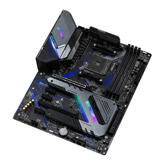
  • Seite 50 1 Einleitung Vielen Dank, dass Sie sich für das X570 Extreme4 von ASRock entschieden haben ein zuverlässiges Motherboard, das konsequent unter der strengen Qualitätskontrolle von ASRock hergestellt wurde. Es liefert ausgezeichnete Leistung mit robustem Design, das ASRock Streben nach Qualität und Beständigkeit erfüllt.
  • Seite 51: Technische Daten

    * Für Prozessoren der Ryzen-Serie (Picasso), ECC wird nur mit PRO-Prozessoren unterstützt. * Weitere Informationen finden Sie in der Speicherkompatibilität- sliste auf der ASRock-Webseite. (http://www.asrock.com/) * Bitte beachten Sie Seite 25 für die maximal unterstützte Frequenz von DDR4-UDIMM. • Systemspeicher, max. Kapazität: 128GB • 15-μ-Goldkontakt in DIMM-Steckplätze...
  • Seite 52 CPUs der AMD-Ryzen-Serie (Pinnacle Ridge) • 2 x PCI-Express 3 . 0-x16-Steckplätze (einzeln bei x16 (PCIE1); doppelt bei x16 (PCIE1) / x4 (PCIE4))* Prozessoren der AMD-Ryzen-Serie (Picasso) • 2 x PCI-Express 3.0-x16-Steckplätze (einzeln bei x8 (PCIE1); doppelt bei x8 (PCIE1) / x4 (PCIE4))* * Unterstützt NVMe-SSD als Bootplatte • 3 x PCI-Express-4.0-x1-Steckplatz • Unterstützt AMD Quad CrossFireX...
  • Seite 53 4 (64 Gb/s)(mit Matisse) oder Gen3 x 4 (32 Gb/s)(mit Pinnacle Ridge und Picasso)* • 1 x Hyper-M.2-Sockel (M2_2), unterstützt M-Key-Typ- 2230/2242/2260/2280/22110-M.2-SATA-III-6,0-Gb/s-Modul und M.2-PCI-Express-Modul bis Gen. 4 x 4 (64 Gb/s)* * Unterstützt NVMe-SSD als Bootplatte * Unterstützt ASRock U.2-Kit...
  • Seite 54 • 1 x Audioanschluss an der Frontblende (15μ goldene Audioan- schluss) • 1 x AMD-LED-Lüfter-USB-Stiftleiste • 1 x Thunderbolt Erweiterungskartenanschluss (5-polig)(Unter- stützt nur ASRock Thunderbolt AIC-Karten) • 2 x USB 2 . 0-Stiftleisten (unterstützt 4 USB 2 . 0-Ports) (unterstützt Schutz gegen elektrostatische Entladung)
  • Seite 55 X570 Extreme4 • 2 x USB 3.2 Gen1-Stiftleiste (unterstützt 4 USB 3.2 Gen1- Ports) (unterstützt Schutz gegen elektrostatische Entla- dung) • 1 x USB-3.2-Gen1-Type-C-Stiftleiste an der Frontblende (unterstützt Schutz gegen elektrostatische Entladung) • AMI-UEFI-Legal-BIOS mit Unterstützung grafischer Be- BIOS-Funk- nutzerschnittstellen tion • Unterstützt „Plug-and-Play“...
  • Seite 56 * Detaillierte Produktinformationen finden Sie auf unserer Webseite: http://www.asrock.com Bitte beachten Sie, dass mit einer Übertaktung, zu der die Anpassung von BIOS-Einstellungen, die Anwendung der Untied Overclocking Technology oder die Nutzung von Übertaktung- swerkzeugen von Drittanbietern zählen, bestimmte Risiken verbunden sind. Eine Übertaktung kann sich auf die Stabilität Ihres Systems auswirken und sogar Komponenten und Geräte Ihres...
  • Seite 57: Jumpereinstellung

    X570 Extreme4 1.3 Jumpereinstellung Die Abbildung zeigt, wie die Jumper eingestellt werden. Wenn die Jumper-Kappe auf den Kontakten angebracht ist, ist der Jumper „kurzgeschlossen“. Wenn keine Jumper-Kappe auf den Kontakten angebracht ist, ist der Jumper „offen“. CMOS-löschen-Jumper Kurzgeschlossen: CMOS (CLRCMOS1) löschen...
  • Seite 58: Integrierte Stiftleisten Und Anschlüsse

    1 . 4 Integrierte Stiftleisten und Anschlüsse Integrierte Stiftleisten und Anschlüsse sind KEINE Jumper. Bringen Sie KEINE Jumper-Kappen an diesen Stiftleisten und Anschlüssen an. Durch Anbringen von Jumper-Kappen an diesen Stiftleisten und Anschlüssen können Sie das Motherboard dauerhaft beschädigen. Systemblende-Stiftleiste Verbinden Sie Ein-/ PLED+ PLED-...
  • Seite 59 X570 Extreme4 Betrieb-LED- und Bitte verbinden Sie die Be- SPEAKER DUMMY Lautsprecher-Stiftleiste trieb-LED des Gehäuses und DUMMY (7-polig, SPK_PLED1) den Gehäuselautsprecher mit (siehe S. 1, Nr. 19) dieser Stiftleiste. PLED+ PLED+ PLED- Serial-ATA-III- Diese acht SATA-III-Anschlüsse Anschlüsse unterstützen SATA-Datenkabel (SATA3_1_2: für interne Speichergeräte mit...
  • Seite 60 Type-C-USB-3.2 Gen1- Es gibt eine Type-C- Stiftleiste für die USB-3.2 Gen1-Stiftleiste für Frontblende die Frontblende an diesem (26-polig, F_USB31_ Motherboard. Diese Stiftleiste TC_1) dient dem Anschluss eines USB- (siehe S. 1, Nr. 17) 3.2 Gen1-Moduls für zusätzliche USB Type-C Cable USB-3.2 Gen1-Ports.
  • Seite 61 X570 Extreme4 (4-polig, CHA_FAN4/ FAN_VOLTAGE CHA_FAN_SPEED FAN_SPEED_CONTROL (siehe S. 1, Nr. 12) CPU-Lüfteranschluss Dieses Motherboard bietet FAN_SPEED_CONTROL CPU_FAN_SPEED (4-polig, CPU_FAN1) einen 4-poligen CPU-Lüfteran- FAN_VOLTAGE (siehe S. 1, Nr. 3) schluss (lautloser Lüfter). Falls Sie einen 3-poligen CPU-Lüfter anschließen möchten, verbinden Sie ihn bitte mit Kontakt 1 bis 3.
  • Seite 62 ATX-12-V-Netzanschluss An diesen Anschluss (4-polig, ATX12V2) schließen Sie ein ATX-12 (siehe S. 1, Nr. 2) V-Netzteil an. *Der Netzteilstecker passt nur in einer Richtung in diesen Anschluss. Thunderbolt- Bitte verbinden Sie Erweiterungskartenanschluss eine Thunderbolt™- (5-polig, TB1) Erweiterungskarte über das (siehe S. 1, Nr. 28) GPIO-Kabel mit diesem Thunderbolt-AIC-Anschluss.
  • Seite 63 X570 Extreme4 AMD-Lüfter-LED-Stiftleiste Die AMD-Lüfter-LED-Stift- leiste dient dem Anschluss des (4-polig, AMD_FAN_LED1) mit dem AMD-Kühlkörpers (siehe S. 1, Nr. 7) gelieferten RGB-LED-Ver- längerungskabels. Der Kabelanschluss ermöglicht Nutzern die Wahl zwischen verschiedenen LED-Lichteffe- kten. * Die AMD-Lüfter-LED- Steckleiste ist mit einer her- kömmlichen RGB-LED-Leiste...
  • Seite 64: Contenu De L'emballage

    Nous vous remercions d’avoir acheté cette carte mère ASRock X570 Extreme4, une carte mère fiable fabriquée conformément au contrôle de qualité rigoureux et constant appliqué par ASRock. Fidèle à son engagement de qualité et de durabilité, ASRock vous garantit une carte mère de conception robuste aux performances élevées.
  • Seite 65: Spécifications

    X570 Extreme4 1.2 Spécifications Plateforme • Facteur de forme ATX • PCB cuivre 2 onces Processeur • Prend en charge la gamme de processeurs AMD AM4 socket Ryzen™ 2000 et 3000 • PWM numérique Intersil • Alimentation à 10 phases Chipset • AMD X570...
  • Seite 66 Processeurs AMD série Ryzen (Pinnacle Ridge) • 2 x fentes PCI Express 3.0 x16 (simple en mode x16 (PCIE1) ; double en mode x16 (PCIE1) / x4 (PCIE4))* Processeurs AMD série Ryzen (Picasso) • 2 x fentes PCI Express 3.0 x16 (simple en mode x8 (PCIE1) ; double en mode x8 (PCIE1) / x4 (PCIE4))* * Prend en charge les SSD NVMe comme disques de démarrage • 3 x fentes PCI Express 4.0 x1...
  • Seite 67 • 1 x socket Hyper M.2 (M2_2), prend en charge les modules M.2 SATA3 6,0 Go/s type 2230/2242/2260/2280/22110 touche M et M.2 PCI Express jusqu'à Gen4 x4 (64 Go/s)* * Prend en charge les SSD NVMe comme disques de démarrage * Prend en charge le kit ASRock U.2...
  • Seite 68 • 1 x embase USB de ventilateur LED AMD • 1 x connecteur Thunderbolt AIC (5 broches) (Prise en charge de la carte ASRock Thunderbolt AIC uniquement) • 2 x embases USB 2.0 (4 ports USB 2.0 pris en charge) (Protection...
  • Seite 69 • ErP/EuP Ready (alimentation ErP/EuP ready requise) * pour des informations détaillées de nos produits, veuillez visiter notre site : http://www.asrock.com Il est important de signaler que l’overclocking présente certains risques, incluant des modifica- tions du BIOS, l’application d’une technologie d’overclocking déliée et l’utilisation d’outils d’overclocking développés par des tiers.
  • Seite 70 1.3 Configuration des cavaliers (jumpers) L’illustration ci-dessous vous renseigne sur la configuration des cavaliers (jumpers). Lorsque le capuchon du cavalier est installé sur les broches, le cavalier est « court- circuité ». Si le capuchon du cavalier n’est pas installé sur les broches, le cavalier est « ouvert ».
  • Seite 71 X570 Extreme4 1.4 Embases et connecteurs de la carte mère Les embases et connecteurs situés sur la carte NE SONT PAS des cavaliers. Ne placez JAMAIS de capuchons de cavaliers sur ces embases ou connecteurs. Placer un capuchon de cavalier sur ces embases ou connecteurs endommagera irrémédiablement votre carte mère.
  • Seite 72 Prise DEL d’alimentation Veuillez brancher la DEL SPEAKER DUMMY et haut-parleur d'alimentation du châssis et le DUMMY (SPK_PLED1 à 7 broches) haut-parleur du châssis sur ce (voir p.1, No. 19) connecteur. PLED+ PLED+ PLED- Connecteurs Serial ATA3 Ces huit connecteurs SATA3 (SATA3_1_2: sont compatibles avec les câbles voir p.1, No.
  • Seite 73 X570 Extreme4 Embase USB 3 . 2 Gen1 Cette carte mère comprend une Type C sur panneau avant embase USB 3 . 2 Gen1 Type C sur (F_USB31_TC_1 à 26 le panneau avant. Cette embase broches) sert à connecter un module USB (voir p.1, No.
  • Seite 74 (CHA_FAN4/WP à 4 FAN_VOLTAGE broches) CHA_FAN_SPEED FAN_SPEED_CONTROL (voir p.1, No. 12) Connecteur du Cette carte mère est dotée d’un FAN_SPEED_CONTROL CPU_FAN_SPEED ventilateur du processeur connecteur pour ventilateur de FAN_VOLTAGE (CPU_FAN1 à 4 broches) processeur (Quiet Fan) à 4 broch- (voir p.1, No. 3) es.
  • Seite 75 X570 Extreme4 Connecteur Veuillez connecter une source d’alimentation ATX 12V d'alimentation ATX 12 V à ce (ATX12V2 à 4 broches) connecteur. (voir p.1, No. 2) *La fiche d'alimentation élec- trique s'adapte à ce connecteur dans un seul sens. Connecteur Thunderbolt Veuillez connecter une carte d’extension (AIC) Thunderbolt™...
  • Seite 76 Embase LED de VENTI- L'embase LED de VENTILA- LATEUR AMD TEUR AMD sert à connecter (AMD_FAN_LED1 à 4 le câble d'extension LED RVB broches) fourni avec un dissipateur (voir p.1, No. 7) thermique AMD. La connexion par câble permet aux utilisateurs de choisir parmi plusieurs effets lumineux LED.
  • Seite 77: Contenuto Della Confezione

    Nel caso di eventuali modifiche della presente documentazione, la versione aggiornata sarà disponibile sul sito Web di ASRock senza ulteriore preavviso. Per il supporto tecnico correlato a questa scheda madre, visitare il nostro sito Web per informazioni specifiche relative al modello attualmente in uso.
  • Seite 78 * Per le CPU serie Ryzen (Picasso), è supportata solo la memoria ECC senza CPU PRO. * Per maggiori informazioni fare riferimento all'elenco dei supporti di memoria sul sito di ASRock. (http://www.asrock.com/) * Fare riferimento a pagina 25 per il supporto della frequenza massima DDR4 UDIMM.
  • Seite 79 X570 Extreme4 CPU serie AMD Ryzen (Picasso) • 2 x Alloggi PCI Express 3.0 x16 (singolo a x8 (PCIE1); doppio a x8 (PCIE1) / x4 (PCIE4))* * Supporto di SSD NVMe come disco d’avvio • 3 x alloggi PCI Express 4.0 x1 • Supporta AMD Quad CrossFireX...
  • Seite 80 • 1 x socket Hyper M.2 (M2_2), supporta il modulo M.2 SATA3 6,0 Gb/s di tipo 2230/2242/2260/2280/22110 ed il modulo M.2 PCI Express fino a Gen4 x4 (64 Gb/s)* * Supporto di SSD NVMe come disco d’avvio * Supporta kit ASRock U.2...
  • Seite 81 X570 Extreme4 Connettore • 1 x connettore TPM • 1 x connettore SPI TPM • 1 x connettore LED alimentazione e altoparlante • 1 x Collettore LED ventola AMD * Il connettore del LED della ventola AMD è compatibile con una normale striscia a LED RGB.
  • Seite 82 • ErP/EuP Ready (è necessaria alimentazione ErP/EuP ready) * Per informazioni dettagliate sul prodotto, visitare il nostro sito Web: http://www.asrock.com Prestare attenzione al potenziale rischio previsto nella pratica di overclocking, inclusa la regolazione delle impostazioni nel BIOS, l'applicazione di tecnologia di Untied Overclocking o l'utilizzo di strumenti di overclocking di terze parti.
  • Seite 83 X570 Extreme4 1.3 Impostazione jumper L'illustrazione mostra in che modo vengono impostati i jumper. Quando il cappuccio del jumper è posizionato sui pin, il jumper è "cortocircuitato". Se sui pin non è posizionato alcun cappuccio del jumper, il jumper è "aperto".
  • Seite 84 1.4 Header e connettori su scheda Gli header e i connettori sulla scheda NON sono jumper. NON posizionare cappucci del jumper su questi header e connettori. Il posizionamento di cappucci del jumper su header e connettori provocherà danni permanenti alla scheda madre. Header sul pannello del Collegare il tasto PLED+...
  • Seite 85 X570 Extreme4 Connettore LED Collegare i LED alimentazione e SPEAKER DUMMY alimentazione e l’altoparlante a questo connet- DUMMY altoparlante tore. (SPK_PLED1 a 7 pin) (vedere pag. 1, n. 19) PLED+ PLED+ PLED- Connettori Serial ATA3 Questi otto connettori SATA3 (SATA3_1_2: supportano cavi di trasmissione vedere pag.
  • Seite 86 Connettore USB 3 . 2 Gen1 È presente un connettore USB 3 . 2 tipo C pannello anteriore Gen1 tipo C pannello anteriore (F_USB31_TC_1 a 26 pin) su questa scheda madre. Questo (vedere pag. 1, n. 17) connettore viene utilizzato per il collegamento di un modulo USB 3 .
  • Seite 87 X570 Extreme4 (CHA_FAN4/WP a 4 pin) FAN_VOLTAGE (vedere pag. 1, n. 12) CHA_FAN_SPEED FAN_SPEED_CONTROL Connettore ventola CPU Questa scheda madre è dotata di FAN_SPEED_CONTROL CPU_FAN_SPEED (CPU_FAN1 a 4 pin) un connettore per la ventola della FAN_VOLTAGE (vedere pag. 1, n. 3) CPU (Ventola silenziosa) a 4 pin.
  • Seite 88 Connettore di Collegare un alimentatore ATX a alimentazione ATX da 12 V 12 V a questo connettore. (ATX12V2 a 4 pin) *La spina di alimentazione può (vedere pag. 1, n. 2) essere inserita in questo connet- tore con un solo orientamento. ConnettoreThunderbolt Collegare una scheda aggiuntiva Thunderbolt™...
  • Seite 89 X570 Extreme4 Collettore LED AMD Il collettore LED AMD FAN viene utilizzato per collegare la (AMD_FAN_LED1 a 4 prolunga LED RGB in dotazione pin) con dissipatore di calore AMD. Il (vedere pag. 1, n. 7) collegamento del cavo consente agli utenti di selezionare tra vari effetti di illuminazione a LED.
  • Seite 90: Contenido Del Paquete

    Si esta documentación sufre alguna modificación, la versión actualizada estará disponible en el sitio web de ASRock sin previo aviso. Si necesita asistencia técnica relacionada con esta placa base, visite nuestro sitio web para obtener información específica sobre el modelo que esté...
  • Seite 91: Especificaciones

    * Para CPU de la serie Ryzen (Picasso), ECC solamente se admite con CPU PRO. * Para obtener más información, consulte la lista de memorias compatibles en el sitio web de ASRock. (http://www.asrock.com/) * Consulte la página 25 para conocer las frecuencias máximas compatibles de DDR4 UDIMM.
  • Seite 92 CPU de la serie AMD Ryzen (Picasso) • 2 x Ranuras PCI Express 3.0 x16 (una sola a x8 (PCIE1); doble a x8 (PCIE1) / x4 (PCIE4))* * Admite unidad de estado sólido de NVMe como disco de arranque • 3 x Ranuras PCI Express 4.0 x1 • Compatible con AMD Quad CrossFireX y CrossFireX • 1 x Zócalo M.2 (clave E), admite el tipo de módulo 2230 WiFi/BT...
  • Seite 93 • 1 x Zócalo Hyper M.2 (M2_2) que admite el módulo SATA3 6,0 Gb/s M.2 de tipo 2230/2242/2260/2280/22110 con clave M y el módulo PCI Express M.2 hasta Gen4 x4 (64 Gb/s)* * Admite unidad de estado sólido de NVMe como disco de arranque * Admite el Kit U.2 de ASRock...
  • Seite 94 Conector • 1 x Conector TPM • 1 x Conector SPI TPM • 1 x LED de alimentación y base de conexiones para el altavoz • 1 x Base de conexiones de LED de ventilador AMD * La base de conexiones de LED del ventilador AMD es compatible con una tira de LED RGB convencional.
  • Seite 95 ErP/EuP) * Para obtener información detallada del producto, visite nuestro sitio Web: http://www.asrock.com Tenga en cuenta que hay un cierto riesgo implícito en las operaciones de overclocking, incluido el ajuste de la BIOS, aplicando la tecnología de overclocking liberada o utilizando las her- ramientas de overclocking de otros fabricantes.
  • Seite 96 1.3 Instalación de los puentes La instalación muestra cómo deben instalarse los puentes. Cuando la tapa de puente se coloca en los contactos, el puente queda “Corto”. Si no coloca la tapa de puente en los contactos, el puente queda “Abierto”. Puente de borrado de Corto: Borrado de CMOS CMOS...
  • Seite 97 X570 Extreme4 1.4 Conectores y cabezales incorporados Los cabezales y conectores incorporados NO son puentes. NO coloque tapas de puente sobre estos cabezales y conectores. Si coloca tapas de puente sobre los cabezales y conectores dañará de forma permanente la placa base.
  • Seite 98 LED de alimentación y Conecte el LED de alimentación SPEAKER DUMMY base de conexiones para del chasis y el altavoz del chasis DUMMY la altavoz a esta base de conexiones. (SPK_PLED1 de 7 contactos) PLED+ (consulte la pág. 1, nº 19) PLED+ PLED- Conectores Serie ATA3...
  • Seite 99 X570 Extreme4 Base de conexiones USB Existe una base de conexiones 3 . 2 Gen1 de tipo C en el USB 3 . 2 Gen1 de tipo C en el panel frontal panel frontal en esta placa base. (F_USB31_TC_1 de 26...
  • Seite 100 (CHA_FAN4/WP de 4 FAN_VOLTAGE contactos) CHA_FAN_SPEED FAN_SPEED_CONTROL (consulte la pág. 1, nº 12) Conector del ventilador Esta placa base contiene un FAN_SPEED_CONTROL CPU_FAN_SPEED de la CPU conector de ventilador (ventilador FAN_VOLTAGE (CPU_FAN1 de 4 silencioso) de CPU de 4 contac- contactos) tos.
  • Seite 101 X570 Extreme4 Conector de alimentación Conecte una fuente de aliment- ATX de 12V ación ATX 12V en este conector. (ATX12V2 de 4 contactos) *El enchufe de la fuente de (consulte la pág. 1, nº 2) alimentación encaja en este conector en una única dirección.
  • Seite 102 Base de conexiones de La base de conexiones de LED de LED de VENTILADOR VENTILADOR AMD se utiliza para conectar el alagador de LED (AMD_FAN_LED1 de 4 RGB incluido con el disipador contactos) AMD. La conexión del cable (consulte la pág. 1, nº 7) permite a los usuarios elegir entre diferentes efectos de iluminación de LED.
  • Seite 103: Комплект Поставки

    X570 Extreme4 1 Введение Благодарим вас за приобретение надежной системной платы ASRock X570 Extreme4, выпускаемой под постоянным жестким контролем качества компании ASRock. Эта материнская плата обеспечивает великолепную производительность и отличается надежной конструкцией в соответствии с требованиями компании ASRock в отношении качества и долговечности.
  • Seite 104: Технические Характеристики

    * Для процессоров серии Ryzen (Picasso) модуль памяти ECC поддерживается только процессорами PRO. * Дополнительная информация представлена в Списке совместимой памяти (Memory Support List ) на веб-сайте ASRock. (http://www.asrock.com/) * Максимальные поддерживаемые частоты DDR4 UDIMM см на стр. 25. • Максимальный объем ОЗУ: 128 Гб...
  • Seite 105 X570 Extreme4 ЦП серии AMD Ryzen (Picasso) • 2 x PCI Express 3.0 x16 гнезд (одинарный при x8 (PCIE1); двойной при x8 (PCIE1) / x4 (PCIE4))* * Поддерживаются в качестве загрузочных SSD-диски типа NVMe • 3 слота PCI Express 4.0 x1 • Поддержка...
  • Seite 106 - Технология Direct Drive - Изолирующее экранирование печатной платы - Определение сопротивления нагрузки, подключенной к линейному выходу. - Отдельные слои печатной платы для левого и правого аудиоканалов - Позолоченный аудиоразъем (15 мкм) • Поддержка DTS-подключения • Gigabit Ethernet 10/100/1000 Мбит/с • GigaLAN Intel® I211AT • Поддерживается...
  • Seite 107 способностью 6,0 Гб/с и модуль M.2 PCI Express до версии Gen4 x4 (64 Гб/с) с ключом M.* * Поддерживаются в качестве загрузочных SSD-диски типа NVMe * Поддерживается комплект ASRock U.2 Разъемы • 1 колодка ТРМ • 1 колодка SPI ТРМ • 1 колодка светодиодного индикатора питания и...
  • Seite 108 • 1 колодка USB для подключения вентилятора AMD со светодиодной подсветкой • 1 AIC-разъем Thunderbolt (5-контактный) (Поддерживает только карту ASRock Thunderbolt AIC) • 2 колодки USB 2.0 (4 порта USB 2.0, с защитой от электростатических разрядов) • 2 колодка USB 3.2 Gen1 (4 порта USB 3.2 Gen1) (с защитой...
  • Seite 109 • FCC, CE • Совместимость с ErP/EuP (необходим блок питания, соответствующий стандарту ErP/EuP) * С дополнительной информацией об изделии можно ознакомиться на веб-сайте: http://www.asrock.com Следует учитывать, что разгон процессора, включая изменение настроек BIOS, применение технологии Untied Overclocking и использование инструментов разгона...
  • Seite 110 1.3 Установка перемычек Установка перемычек показана на рисунке. При установке перемычки-колпачка на контакты перемычка «замкнута». Если перемычка-колпачок на контакты не установлена, перемычка «разомкнута». Перемычка сброса Замкнута: Сброс настроек настроек CMOS CMOS 2-контактная перемычка (CLRCMOS1) Разомкнута: По умолчанию (см. стр. 1, № 23) CLRCMOS1 используется...
  • Seite 111 X570 Extreme4 1.4 Колодки и разъемы, расположенные на системной плате Расположенные на системной плате колодки и разъемы НЕ являются перемычками. НЕ устанавливайте на эти колодки и разъемы перемычки-колпачки. Установка перемычек- колпачков на эти колодки и разъемы может вызвать неустранимое повреждение...
  • Seite 112 Колодка светодиодного Предназначена для SPEAKER DUMMY индикатора питания и подключения светодиодного DUMMY динамика корпуса индикатора питания и (7-контактная, SPK_ динамика корпуса. PLED1) PLED+ (см. стр. 1, № 19) PLED+ PLED- Разъемы Serial ATA3 Эти шесть восемь SATA3 (SATA3_1_2: предназначены для см.
  • Seite 113 X570 Extreme4 Колодка для порта На материнской плате USB 3.2 Gen1 Type C на предусмотрена одна колодка передней панели для порта USB 3.2 Gen1 Type (26 контактов, F_USB31_ C на передней панели. Эта TC_1) колодка используется для (см. стр. 1, № 17) подключения...
  • Seite 114 (4-контактный CHA_ FAN_VOLTAGE FAN4/WP) CHA_FAN_SPEED (см. стр. 1,№ 12) FAN_SPEED_CONTROL Разъем вентилятора Эта материнская плата FAN_SPEED_CONTROL CPU_FAN_SPEED снабжена 4-контактным охлаждения процессора FAN_VOLTAGE разъемом для малошумящего (4-контакта, CPU_FAN1) вентилятора ЦП. Если вы (см. стр. 1,№ 3) собираетесь подключить 3-контактный вентилятор охлаждения процессора, подключайте его к контактам 1-3.
  • Seite 115 X570 Extreme4 Разъем питания АТХ 12 В К данному разъему подключается источник (4 контактов, ATX12V2) питания ATX 12 В. (см. стр. 1, № 2) *Разъем от блока питания подсоединяется к этому разъему только в одной ориентации. Разъем Thunderbolt AIC Подключите плату...
  • Seite 116 Колодка для Колодка для подключения подключения светодиодной подсветки светодиодной вентилятора AMD служит для подсветки вентилятора подключения удлинительного AMD. кабеля светодиодной (4-контактная, AMD_ RGB-подсветки, который FAN_LED1) поставляется с кулером AMD. (см. стр. 1, № 7) Подключив этот кабель, можно различные световые эффекты. * Колодка...
  • Seite 117: Conteúdo Da Embalagem

    Se precisar de assistência técnica relacionada a esta placa principal, visite o nosso site para obter informações específicas sobre o modelo que estiver utilizando. Você também poderá encontrar a lista de placas VGA e CPU mais recentes suportadas no site da ASRock. Site da ASRock http://www.asrock.com.
  • Seite 118 * Para CPUs série Ryzen (Picasso), ECC só é suportado com CPUs PRO. * Por favor, consulte a Lista de Suporte de Memória no site da ASRock para obter mais informação. (http://www.asrock.com/) * Por favor consulte a página 25 para suporte de frequência máxima DDR4 UDIMM.
  • Seite 119 X570 Extreme4 CPUs AMD séries Ryzen (Picasso) • 2 x PCI Express 3.0 x16 Slots (único em x8 (PCIE1); duplos em x8 (PCIE1) / x4 (PCIE4))* * Suporta NVMe SSD nos discos de inicialização • 3 x Slots PCI Express 4.0 x1 • Suporta AMD Quad CrossFireX...
  • Seite 120 • 1 x Soquete Hyper M.2 (M2_2), suporta Chave M tipo 2230/2242/2260/2280/22110 módulo M.2 SATA3 6,0 Gb/s e módulo M.2 PCI Express até Gen4 x4 (64 Gb/s)* * Suporta NVMe SSD nos discos de inicialização * Suporta Kit U.2 ASRock...
  • Seite 121 • 1 x Conector de áudio de painel frontal (Conector de Áudio de Outro 15μ) • 1 x Plataforma AMD LED Fan USB • 1 x Conector Thunderbolt AIC (5 pinos)(Suporta Cartão ASRock Thunderbolt AIC única) • 2 x Plataformas USB 2.0 (Suporta 4 portas USB 2.0) (Suporta...
  • Seite 122 • Preparada para ErP/EuP (é necessária uma fonte de alimen- tação preparada para ErP/EuP) * Para obter informações detalhadas sobre o produto, por favor, visite o nosso site: http://www.asrock.com Por favor, observe que existe um certo risco envolvendo overclocking, incluindo o ajuste das definições na BIOS, a aplicação de tecnologia Untied Overclocking ou a utilização de ferra-...
  • Seite 123 X570 Extreme4 1.3 Configuração dos jumpers A imagem abaixo mostra como os jumpers são configurados. Quando a tampa do jumper é colocada nos pinos, o jumper é "Curto". Se não for colocada uma tampa de jumper nos pinos, o jumper é "Aberto".
  • Seite 124 1 . 4 Suportes e conectores onboard Os conectores e suportes onboard NÃO são jumpers. NÃO coloque tampas de jumpers sobre estes terminais e conectores Colocar tampas de jumpers sobre os terminais e conectores irá causar danos permanentes à placa-mãe. Suporte do painel de Ligue o botão de alimentação, PLED+...
  • Seite 125 X570 Extreme4 LED de alimentação e Conecte o LED de alimentação SPEAKER DUMMY Cabeçote de Autofalante do chassi e o autofalante do DUMMY (SPK_PLED1 de 7 pinos) chassi a este cabeçote. (ver p.1, N.º 19) PLED+ PLED+ PLED- Conectores série ATA3...
  • Seite 126 Painel Frontal Cabeçote Há um Painel Frontal Cabeçote USB 3.2 Gen1 Tipo C USB 3.2 Gen1 Tipo C nesta placa (F_USB31_TC_1 de 26 mãe. Este cabeçote é utilizado pinos) para conectar um módulo USB (ver p.1, N.º 17) 3.2 Gen1 a portas adicionais USB 3.2 Gen1.
  • Seite 127 X570 Extreme4 (4-pin CHA_FAN4/WP) FAN_VOLTAGE (ver p.1, N.º 12) CHA_FAN_SPEED FAN_SPEED_CONTROL Conector da Ventoinha Esta placa mãe inclui um FAN_SPEED_CONTROL CPU_FAN_SPEED da CPU conector de ventilador da CPU FAN_VOLTAGE (CPU_FAN1 de 4 pinos) (Ventilador silencioso) de 4 (ver p.1, N.º 3) pinos.
  • Seite 128 Conector de alimentação Por favor, ligue este conector a de 12V ATX uma alimentação de força ATX (ATX12V2 de 4 pinos) 12V. (ver p.1, N.º 2) *O plugue de sua fonte de ali- mentação se encaixa neste conec- tor apenas em uma orientação. Conector Thunderbolt Por favor, conecte uma placa adicional Thunderbolt™...
  • Seite 129 X570 Extreme4 Cabeçote de LED FAN Cabeçote de LED FAN AMD é usado para conectar o cabo de (AMD_FAN_LED1 de 4 extensão de LED RGB que vem pinos) com dissipador de calor AMD. (ver p.1, N.º 7) A conexão de cabo permite aos usuários escolher entre vários...
  • Seite 130: Zawartość Opakowania

    ASRock, bez dalszego powiadomienia. Jeśli wymagana jest pomoc techniczna w odniesieniu do tej płyty głównej, należy odwiedzić stronę internetową w celu uzyskania specy- ficznych informacji o używanym modelu. Na stronie internetowej ASRock, można także pobrać listę najnowszych kart VGA i obsługiwanych CPU. Strona internetowa ASRock http://www.asrock.com.
  • Seite 131 * Dla serii CPU Ryzen (Picasso), ECC jest obsługiwana tylko z CPU PRO. * Sprawdź listę obsługiwanej pamięci na stronie internetowej ASRock w celu uzyskania dalszych informacji. (http://www.asrock. com/) * Sprawdź stronę 25 w celu uzyskania informacji o maksymalnej obsługiwanej częstotliwości DDR4 UDIMM.
  • Seite 132 Procesor serii AMD Ryzen (Pinnacle Ridge) • 2 x gniazda PCI Express 3.0 x16 (pojedyncze w x16 (PCIE1); podwójne w x16 (PCIE1) / x4 (PCIE4))* Procesor serii AMD Ryzen (Picasso) • 2 x gniazda PCI Express 3.0 x16 (pojedyncze w x8 (PCIE1); podwójne w x8 (PCIE1) / x4 (PCIE4))* * Obsługa SSD NVMe, jako dysków rozruchowych • 3 x gniazda PCI Express 4.0 x1...
  • Seite 133 • 1 x gniazdo Hyper M.2 (M2_2), obsługa Key M typu 2230/2242/ 2260/2280/22110 modułu M.2 SATA3 6,0 Gb/s i modułu M.2 PCI Express do Gen4 x4 (64 Gb/s)* * Obsługa SSD NVMe, jako dysków rozruchowych * Obsługa ASRock U.2 Kit...
  • Seite 134 • 1 x złącze audio na panelu przednim (15μ pozłacane złącze au- dio) • 1 x złącze główkowe wentylatora LED AMD • 1 x złącze Thunderbolt AIC (5-pinowe) (Obsługuje tylko karty ASRock Thunderbolt AIC) • 2 x złącza główkowe USB 2.0 (Obsługa 4 portów USB 2.0) (Obsłu- ga zabezpieczenia ESD)
  • Seite 135 X570 Extreme4 • 2 x porty główkowe USB 3.2 Gen1 (Obsługa 4 portów USB 3.2 Gen1) (Obsługa zabezpieczenia ESD) • 1 x złącze główkowe USB 3.2 Gen1 typu C panelu czołowego (obsługa zabezpieczenia ESD) • Obsługa starszych wersji BIOS AMI UEFI z GUI Funkcja • Obsługa “Plug and Play”...
  • Seite 136 * Dla uzyskania szczegółowej informacji o produkcie, należy odwiedzić naszą stronę internetową: http://www.asrock.com Należy pamiętać, że przetaktowywanie jest związane z pewnym ryzykiem, włącznie z regulacją ustawień w BIOS, zastosowaniem Untied Overclocking Technology lub używaniem narzędzi przetaktowywania innych firm. Przetaktowywanie może wpływać na stabilność systemu lub nawet powodować...
  • Seite 137 X570 Extreme4 1.3 Ustawienia zworek Ta ilustracja pokazuje ustawienia zworek. Po umieszczeniu nasadki zworki na pinach, zworka jest “Zwarta”. Jeśli nasadka zworki nie jest umieszczona na pinach, zworka jest “Otwarta”. Zworka usuwania danych Zwarcie: Usunięcie danych z z pamięci CMOS pamięci CMOS...
  • Seite 138 1.4 Wbudowane złącza główkowe i inne złącza Wbudowane złącza główkowe i inne złącza są bezzworkowe. NIE należy umieszczać zworek nad tymi złączami główkowymi i złączami. Umieszczanie zworek nad złączami główkowymi i złączami spowoduje trwałe uszkodzenie płyty głównej. Złącze główkowe na pan- Do tego złącza główkowego PLED+ PLED-...
  • Seite 139 X570 Extreme4 Dioda LED zasilania Podłącz to tego złącza SPEAKER DUMMY i złącze główkowe główkowego diodę LED zasila- DUMMY głośnika nia obudowy i głośnik obudowy (7-pinowe SPK_PLED1) (sprawdź s.1, Nr 19) PLED+ PLED+ PLED- Złącza Serial ATA3 Te osiem złączy SATA3 (SATA3_1_2: obsługuje kable danych SATA...
  • Seite 140 Złącze główkowe Gen1 Na tej płycie głównej dostępne USB 3.2 typu C panelu jest jedno złącze główkowe przedniego Gen1 USB 3.2 typu C panelu (26-pinowe F_USB31_ przedniego. To złącze główkowe TC_1) jest używane do podłączania (sprawdź s.1, Nr 17) modułu USB 3.2 Gen1 dla USB Type-C Cable dodatkowych portów USB 3.2 Gen1.
  • Seite 141 X570 Extreme4 (4-pinowe CHA_FAN4/ FAN_VOLTAGE CHA_FAN_SPEED FAN_SPEED_CONTROL (sprawdź s.1, Nr 12) Złącze wentylatora CPU Ta płyta główna udostępnia FAN_SPEED_CONTROL CPU_FAN_SPEED (4-pinowe CPU_FAN1) 4-pinowe złącze wentylatora FAN_VOLTAGE (sprawdź s.1, Nr 3) CPU (Cichy wentylator). Jeśli planowane jest podłączenie 3-pinowego wentylatora CPU, należy je podłączyć...
  • Seite 142 Złącze zasilania ATX 12V Podłącz do tego złącza zasilacz (4-pinowe ATX12V2) ATX 12V. (sprawdź s.1, Nr 2) *Wtyczka zasilacza pasuje do tego złącza tylko w jednym kierunku. Złącze Thunderbolt AIC Podłącz dodatkową kartę (5-pinowe TB1) Thunderbolt™ (AIC) do złącza (sprawdź s.1, Nr 28) Thunderbolt AIC przez kabel GPIO.
  • Seite 143 X570 Extreme4 Złącze główkowe LED Złącze główkowe LED wen- tylatora AMD jest używane do wentylatora AMD podłączenia przedłużacza LED (4-pinowe AMD_FAN_ RGB, dostarczonego z radiato- LED1) rem AMD. Połączenie kablowe (sprawdź s.1, Nr 7) umożliwia użytkownikom wybór spośród różnych efektów światła LED.
  • Seite 144 마더보드 규격과 BIOS 소프트웨어를 업데이트할 수도 있기 때문에 , 이 문서의 내용은 예고 없이 변경될 수 있습니다 . 이 설명서가 변경될 경우 , 업데이트된 버전은 ASRock 의 웹사이트 에서 추가 통지 없이 제공됩니다 . 이 마더보드와 관련하여 기술적 지원이 필요한 경우 , 당사...
  • Seite 145 원합니다 .* * Ryzen Series CPU(Picasso) 의 경우 , ECC 는 PRO CPU 에서만 지 원합니다 . * 추가 정보를 원하시면 ASRock 웹사이트에 있는 메모리 지원 목록 을 참조하십시오 . (http://www.asrock.com/) * DDR4 UDIMM 최대 주파수 지원은 25 페이지를 참조하십시오 .
  • Seite 146 AMD Ryzen 시리즈 CPU(Pinnacle Ridge) • PCI Express 3.0 x16 슬롯 2 개 ( 단일 @ x16(PCIE1), 이중 @ x16(PCIE1) / x4 (PCIE4))* AMD Ryzen 시리즈 CPU (Picasso) • PCI Express 3.0 x16 슬롯 2 개 ( 단일 @ x8 (PCIE1), 이중 @ x8(PCIE1) / x4 (PCIE4))* * NVMe SSD 를...
  • Seite 147 • 울트라 M.2 하이퍼 1 개 (M2_2), M 키 타입 2230/2242/2260/2280/22110 M.2 SATA3 6.0 Gb/s 모듈 및 Gen4 M.2 PCI Express 모듈을 4 개 (64 Gb/s) 까지 지원 * * NVMe SSD 를 부팅 디스크로 사용 가능하도록 지원 * ASRock U.2 키트 지원...
  • Seite 148 • 전면 패널 오디오 커넥터 1 개 (15 µ 골드 오디오 커넥터 ) • AMD LED 팬 USB 헤더 1 개 • Thunderbolt AIC 커넥터 1 개 (5 핀 )(ASRock Thunderbolt AIC 카드 만 지원 ) • USB 2.0 헤더 2 개 (USB 2.0 포트 4 개 지원 ) (ESD 보호 지원 ) •...
  • Seite 149 인증 • ErP/EuP 사용 가능 (ErP/EuP 사용 가능 전원공급장치 필요 ) * 자세한 제품 정보에 대해서는 당사 웹사이트를 참조하십시오 : http://www.asrock.com BIOS 설정을 조정하거나 Untied Overclocking Technology 를 적용하거나 타업체의 오버클 로킹 도구를 사용하는 것을 포함하는 오버클로킹에는 어느 정도의 위험이 따른다는 것을...
  • Seite 150 1.3 점퍼 설정 그림은 점퍼를 어떻게 설정하는지 보여줍니다 . 점퍼 캡을 핀에 씌우면 점퍼가 “단락” 됩니다 . 점퍼 캡을 핀에 씌우지 않으면 점퍼가 “단선”됩니다 . Clear CMOS 점퍼 단락 : Clear CMOS (CLRCMOS1) 단선 : 기본값 2 핀 점퍼 (1 페이지 , 23 번 항목 참 조...
  • Seite 151 X570 Extreme4 1.4 온보드 헤더 및 커넥터 온보드 헤더와 커넥터는 점퍼가 아닙니다 . 점퍼 캡을 온보드 헤더와 커넥터에 씌우지 마십시 오 . 점퍼 캡을 온보드 헤더와 커넥터에 씌우면 마더보드가 영구적으로 손상됩니다 . 섀시의 전원 버튼 , 리셋 버튼 , 시스템 패널 헤더...
  • Seite 152 전원 LED 및 스피커 헤더 섀시 전원 LED 와 섀시 스피커 SPEAKER DUMMY (7 핀 SPK_PLED1) 를 이 헤더에 연결하십시오 . DUMMY (1 페이지 , 19 번 항목 참조 ) PLED+ PLED+ PLED- 시리얼 ATA3 커넥터 이들 8 개의 SATA3 커넥터는 (SATA3_1_2: 최대...
  • Seite 153 X570 Extreme4 전면 패널 타입 C USB 3.2 이 마더보드에는 전면 패널 타입 Gen1 헤더 C USB 3.2 Gen1 헤더 1 개가 있 (26 핀 F_USB31_TC_1) 습니다 . 이 헤더는 추가 USB 3.2 (1 페이지 , 17 번 항목 참조 ) Gen1 포트용...
  • Seite 154 (4 핀 CHA_FAN4/WP) FAN_VOLTAGE (1 페이지 , 12 번 항목 참조 ) CHA_FAN_SPEED FAN_SPEED_CONTROL CPU 팬 커넥터 이 마더보드에는 4 핀 CPU 팬( 저 FAN_SPEED_CONTROL CPU_FAN_SPEED (4 핀 CPU_FAN1) 소음 팬 ) 커넥터가 탑재되어 있 FAN_VOLTAGE (1 페이지 , 3 번 항목 참조 ) 습니다...
  • Seite 155 X570 Extreme4 ATX 12V 전원 커넥터 ATX 12V 전원공급장치를 이 커 (4 핀 ATX12V2) 넥터에 연결하십시오 . (1 페이지 , 2 번 항목 참조 ) * 전원 공급장치 플러그는 한 방 향으로만 이 커넥터에 끼울 수 있습니다 . Thunderbolt AIC 커넥터...
  • Seite 156 AMD 팬 LED 헤더 AMD 팬 LED 헤더는 AMD 방열 (4 핀 AMD_FAN_LED1) 판과 함께 제공되는 RGB LED 연 (1 페이지 , 7 번 항목 참조 ) 장 케이블을 연결하는 데 사용됩 니다 . 케이블 연결에서 사용자는 다양한 LED 조명 효과를 선택할 수...
  • Seite 157 いての詳細情報を、 当社のウェブサイトで参照ください。 ASRock のウェブサイトでは、 最新 の VGA カードおよび CPU サポート一覧もご覧になれます。 ASRock ウェブサイト http://www.asrock.com. 1.1 パッケージの内容 • ASRock X570 Extreme4 マザーボード (ATX フォームファクタ) • ASRock X570 Extreme4 クイックインストールガイド • ASRock X570 Extreme4 サポート CD • 4 x シリアル ATA (SATA) データケーブル (オプション)...
  • Seite 158 • AMD Ryzen シリーズ CPU (Picasso) は、 DDR4 3466+ (OC)/3200 (OC)/2933/2667/2400/2133 非 ECC、 アンバッファードメモリに 対応します * * Ryzen シリーズ CPU (Picasso) の場合、 ECC は PRO CPU のみに 対応します。 * 詳細については、 ASRock ウェブサイトのメモリーサポート一覧を 参照してください。 (http://www.asrock.com/) * DDR4 UDIMM 最大周波数サポートについては 25 ページを参照 してください。 • システムメモリの最大容量: 128GB •...
  • Seite 159 X570 Extreme4 AMD Ryzen シリーズ CPU (Pinnacle Ridge) • 2 x PCI Express 3.0 x16 スロッ ト (x16 (PCIE1) でシングル、 x16 (PCIE1) /x4 (PCIE4) でデュアル) * AMD Ryzen シリーズ CPU (Picasso) • 2 x PCI Express 3.0 x16 スロッ ト (x8 (PCIE1) でシングル、 x8 (PCIE1) / x4 (PCIE4)...
  • Seite 160 Ridge および Picasso の場合) に対応 * • 1 x Hyper M.2 ソケッ ト (M2_2)、 M Key タイプ 2230/2242/2260/ 2280/22110 M.2 SATA3 6.0 Gb/s モジュールと最大 Gen4 x4 (64 Gb/s) までの M.2 PCI Express モジュールに対応 * * 起動ディスクとして NVMe SSD に対応 * ASRock U.2 キッ トに対応...
  • Seite 161 X570 Extreme4 • 1 x TPM ヘッダー コネクタ • 1 x SPI TPM ヘッダー • 1 x 電源 LED とスピーカーヘッダー • 1 x AMD ファン LED ヘッダー * AMD ファン LED ヘッダーはレギュラー RGB LED ストライプに 対応します。 * AMD ファン LED ヘッダーは、 3A (36W) の最大負荷と 2.5M ま...
  • Seite 162 DRAM、 VPPM、 PREM VDDCR_SOC、 +1.8V、 VDDP • Microsoft® Windows® 10 64-bit 認証 • FCC、 CE • ErP/EuP Ready (ErP/EuP 対応電源供給装置が必要です) * 商品詳細については、 当社ウェブサイトをご覧ください。 http://www.asrock.com BIOS 設定の調整、 アンタイドオーバークロックテク ノロジーの適用、 サードパーティのオーバー クロックツールの使用などを含む、 オーバークロックには、 一定のリスクを伴いますのでご注意 ください。 オーバークロックするとシステムが不安定になったり、 システムのコンポーネント やデバイスが破損することがあります。 ご自分の責任で行ってください。 弊社では、 オーバー クロックによる破損の責任は負いかねますのでご了承ください。...
  • Seite 163 X570 Extreme4 1.3 ジャ ンパー設定 このイラストは、 ジャ ンパーの設定方法を示しています。 ジャ ンパーキャップがピンに 被さっていると、 ジャ ンパーは 「ショート 」 です。 ジャ ンパーキャップがピンに被さってい ない場合には、 ジャ ンパーは 「オープン」 です。 CMOS クリアジャ ンパー ショート : CMOS のクリア オープン : デフォルト (CLRCMOS1) 2 ピンジャンパー (p.1、 No. 23 参照)...
  • Seite 164 1.4 オンボードのヘッダーとコネクタ オンボードヘッダーとコネクタはジャンパーではありません。 これらヘッダーとコネクタには ジャンパーキャップを被せないでください。 ヘッダーおよびコネクタにジャンパーキャップを 被せると、 マザーボードに物理損傷が起こることがあります。 システムパネルヘッダー 電源ボタンを接続し、 ボタン PLED+ PLED- (9 ピン PANEL1) をリセッ トし、 下記のピン割り PWRBTN# (p.1、 No. 18 参照) 当てに従って、 シャーシのシス テムステータス表示ランプを このヘッダーにセッ トします。 RESET# HDLED- ケーブルを接続するときには、 HDLED+ ピンの+と−に気をつけてく ださい。 PWRBTN (電源ボタン) : シャーシ前面パネルの電源ボタンに接続してください。 電源ボタンを使用して、 システム をオフにする方法を設定できます。...
  • Seite 165 X570 Extreme4 電源 LED とスピーカー シャーシ電源 LED とシャーシ SPEAKER DUMMY ヘッダー スピーカーをこのヘッダーに DUMMY (7 ピン SPK_PLED1) 接続してください。 (p.1、 No. 19 参照) PLED+ PLED+ PLED- シリアル ATA3 コネクタ これら 8 つの SATA3 コネクタ は最高 6.0Gb/s のデーター (SATA3_1_2: p.1、 No. 13 参照)...
  • Seite 166 フロントパネルタイプ C このマザーボード上には、 1 つの USB 3.2 Gen1 ヘッダー フロントパネルタイプ C USB 3.2 (26 ピン F_USB31_TC_1) Gen1 ヘッダーがあります。 この (p.1、 No. 17 参照) ヘッダーは、 追加 USB 3.2 Gen1 ポート用に USB 3.2 Gen1 モジュールを接続するために USB Type-C Cable 使用されます。 フロントパネルオーディオ このヘッダーは、 フロントオー PRESENCE# ヘッダー...
  • Seite 167 X570 Extreme4 (4 ピン CHA_FAN4/ FAN_VOLTAGE WP) CHA_FAN_SPEED FAN_SPEED_CONTROL (p.1、 No. 12 参照) CPU ファンコネクタ このマザーボードは 4 ピン CPU FAN_SPEED_CONTROL CPU_FAN_SPEED (4 ピン CPU_FAN1) ファン (静音ファン) コネクタが FAN_VOLTAGE (p.1、 No. 3 参照) 装備されています。 3 ピンの CPU ファンを接続する場合に は、 ピン 1-3 に接続してください。...
  • Seite 168 ATX 12V 電源コネクタ ATX 12V 電源をこのコネクタに (4 ピン ATX12V2) 接続してください。 (p.1、 No. 2 参照) * 電源供給プラグはこのコネク タに 1 方向にしか差し込むこと ができません。 Thunderbolt AIC コネク GPIO ケーブルを使って、 タ Thunderbolt ™ アドインカード (5 ピン TB1) (AIC) を Thunderbolt AIC (p.1、 No. 28 参照) コネクターに接続してください。...
  • Seite 169 X570 Extreme4 AMD ファン LED ヘッダー AMD ファン LED ヘッダーを使 用して AMD ヒートシンクに付属 (4 ピン AMD_FAN_ している RGB LED 延長ケーブル LED1) を接続します。 ケーブルを接続 (p.1、 No. 7 参照) すれば、 ユーザーはさまざまな LED ライティング効果を選択で きます。 * AMD ファン LED ヘッダーは レギュラー RGB LED ストライプ...
  • Seite 170 如果您需要与此主板相关的技术支持,请访问我们的网站以具体了解所用型号的信息。 您 也可以在华擎网站上找到最新 VGA 卡和 CPU 支持列表。 华擎网站 http://www.asrock.com。 1.1 包装清单 • 华擎 X570 Extreme4 主板 (ATX 规格尺寸) • 华擎 X570 Extreme4 快速安装指南 • 华擎 X570 Extreme4 支持光盘 • 4 x 串行 ATA (SATA) 数据线 (选购) • 3 x 螺丝 (供 M.2 插座使用) (选购)...
  • Seite 171 X570 Extreme4 1.2 规格 • ATX 规格尺寸 平台 • 2 盎司纯铜电路板 • 支持 AMD AM4 Socket Ryzen ™ 2000 和 3000 系列处理器 • Intersil 数字 PWM • 10 电源相设计 • AMD X570 芯片集 内存 • 双通道 DDR4 内存技术 • 4 x DDR4 DIMM 槽...
  • Seite 172 • Ryzen 系列 APU 中的集成 AMD Radeon Vega 系列图形 * 图形 * 实际支持可能视 CPU 而变化 • DirectX 12、Pixel Shader 5.0 • 默认共享内存 2GB。 最大共享内存达 16GB。 * 最大共享内存 16GB 需要安装 32GB 系统内存。 • 支持 HDMI 2.0,30Hz 时最大分辨率达 4K x 2K (4096x2160) •...
  • Seite 173 X570 Extreme4 后面板 I/O • 2 x 天线端口 (在 I/O 面板屏蔽端) • 1 x PS/2 鼠标 / 键盘端口 • 1 x HDMI 端口 • 1 x 光学 SPDIF 输出端口 • 1 x USB 3.2 Gen2 A 类型端口 (10 Gb/s) ( 支持 ESD 保护)...
  • Seite 174 • 1 x CPU/ 水泵风扇接口 (4 针) (智能风扇速度控制) * CPU/ 水泵风扇支持最高 2A (24W) 功率的水冷风扇。 • 4 x 机箱 / 水泵风扇接口 (4 针) (智能风扇速度控制) * 机箱 / 水泵风扇支持最高 2A (24W) 功率的水冷风扇。 * CPU_FAN2/WP、CHA_FAN1/WP、CHA_FAN2/WP、CHA_ FAN3/WP 和 CHA_FAN4/WP 可以自动检测 3 针脚或 4 针脚风扇 是否在使用。...
  • Seite 175 X570 Extreme4 * 有关详细产品信息 ,请访问我们的网站: http://www.asrock.com 须认识到超频会有一定风险,包括调整 BIOS 设置,应用 “自由超频技术” ,或使用第三方 超频工具。 超频可能会影响到系统的稳定性,甚至对系统的组件和设备造成损坏。 执行这 项工作您应自担风险和费用。 我们对由于超频而造成的损坏概不负责。...
  • Seite 176 1.3 跳线设置 此图显示如何设置跳线。 将跳线帽装到这些针脚上时,跳线 “短接” 。 如果这些针脚 上没有装跳线帽,跳线 “开路” 。 清除 CMOS 跳线 短接 : 清除 CMOS (CLRCMOS1) 开路 : 默认 2 针跳线 (见第 1 页 ,第 23 个) CLRCMOS1 允许您清除 CMOS 中的数据。 CMOS 中的数据包括系统设置信息 ,如 系统密码、 日期、时间和系统设置参数。 要清除和重置系统参数为默认设置,请关闭 计算机 ,拔下电源线插头,然后使用跳线帽短接 CLRCMOS1 上的针脚 3 秒。 请记住 在清除...
  • Seite 177 X570 Extreme4 1.4 板载接脚和接口 板载接脚和接口不是跳线。 不要将跳线帽装到这些接脚和接口上。 将跳线帽装到这些接脚 和接口上将会对主板造成永久性损坏。 系统面板接脚 按照下面的针脚分配,将机箱 PLED+ PLED- (9 针 PANEL1) 上的电源按钮、 重置按钮和系 PWRBTN# (见第 1 页 , 第 18 个) 统状态指示灯连接到此接脚。 在连接线缆前请记下正负针 脚。 RESET# HDLED- HDLED+ PWRBTN (电源按钮) : 连接到机箱前面板上的电源按钮。 您可以配置使用电源按钮关闭系统的方式。 RESET (重置按钮) : 连接到机箱前面板上的重置按钮。 如果计算机死机,无法执行正常重新启动,按重置按钮...
  • Seite 178 电源 LED 和扬声器接脚 请将机箱电源 LED 和机箱扬声 SPEAKER DUMMY (7 针 SPK_PLED1) 器连接到此接脚。 DUMMY (见第 1 页 ,第 19 个) PLED+ PLED+ PLED- 串行 ATA3 接口 这八个 SATA3 接口支持最高 6.0 Gb/s 数据传输速率的内部 (SATA3_1_2: 见第 1 页 , 第 13 个) 存储设备的 SATA 数据线。 (SATA3_3_4: 见第...
  • Seite 179 X570 Extreme4 前面板类型 C USB 3.2 此主板上有一个前面板类型 C Gen1 接脚 USB 3.2 Gen1 接脚。 此接脚用 (26 针 F_USB31_TC_1) 于连接 USB 3.2 Gen1 模块以获 (见第 1 页 ,第 17 个) 得附加 USB 3.2 Gen1 端口。 USB Type-C Cable 前面板音频接脚 此接脚用于将音频设备连接到 PRESENCE# MIC_RET (9 针...
  • Seite 180 (4 针 CHA_FAN4/WP) FAN_VOLTAGE (见第 1 页 , 第 12 个) CHA_FAN_SPEED FAN_SPEED_CONTROL CPU 风扇接口 此主板提供 4 针 CPU 风扇 (静 FAN_SPEED_CONTROL CPU_FAN_SPEED (4 针 CPU_FAN1) 音风扇) 接口。 如果您打算连接 FAN_VOLTAGE (见第 1 页 , 第 3 个) 3 针 CPU 风扇,请将它连接到针 脚...
  • Seite 181 X570 Extreme4 ATX 12V 电源接口 请将 ATX 12V 电源连接到此接 (4 针 ATX12V2) 口。 (见第 1 页 ,第 2 个) * 电源插头只能从一个方向插入 此接口。 Thunderbolt AIC 接口 请利用 GPIO 线将 (5- 针 TB1) Thunderbolt ™扩展卡 (AIC) 连 (见第 1 页 ,第 28 个)...
  • Seite 182 AMD 风扇 LED 接脚 AMD 风扇 LED 接脚用于连接 (4 针 AMD_FAN_ AMD 散热器附带的 RGB LED LED1) 延长线。 连接线缆可以让用户 (见第 1 页 ,第 7 个) 选择不同的 LED 灯光效果。 * AMD 风扇 LED 接脚兼容普通 RGB LED 灯条。 注意: 风扇 LED 线安装方向切 勿错误, 否则, 线缆会损坏。 RGB LED 接脚...
  • Seite 183 X570 Extreme4 电子信息产品污染控制标示 依据中国发布的「电子信息产品污染控制管理办法」及 SJ/T 11364-2006「电子 信息产品污染控制标示要求」,电子信息产品应进行标示,藉以向消费者揭露 产品中含有的有毒有害物质或元素不致发生外泄或突变从而对环境造成污染或 对人身、财产造成严重损害的期限。依上述规定,您可于本产品之印刷电路板 上看见图一之标示。图一中之数字为产品之环保使用期限。由此可知此主板之 环保使用期限为 10 年。 图一 有毒有害物质或元素的名称及含量说明 若您欲了解此产品的有毒有害物质或元素的名称及含量说明,请参照以下表格 及说明。 有害物质或元素 部件名称 铅 (Pb) 镉 (Cd) 汞 (Hg) 六价铬 (Cr(VI)) 多溴联苯 (PBB) 多溴二苯醚 (PBDE) 印刷电路板 及电子组件 外部信号连 接头及线材 O: 表示该有毒有害物质在该部件所有均质材料中的含量均在 SJ/T 11363-2006 标准规定...
  • Seite 184 本文件有任何修改,可至華擎網站逕行取得更新版本,不另外通知。 若您需要與本主機板 相關的技術支援,請上我們的網站瞭解有關您使用機型的特定資訊。 您也可以在華擎網站 找到最新的 VGA 卡及 CPU 支援清單。 華擎網站 http://www.asrock.com. 1.1 包裝內容 • 華擎 X570 Extreme4 主機板 (ATX 尺寸) • 華擎 X570 Extreme4 快速安裝指南 • 華擎 X570 Extreme4 支援光碟 • 4 x Serial ATA (SATA) 資料纜線 (選用) • 3 x 螺絲 (適用於 M.2 插座) (選用)...
  • Seite 185 X570 Extreme4 1.2 規格 • ATX 尺寸 平台 • 2oz 銅製 PCB • 支援 AMD AM4 socket Ryzen ™ 2000 及 3000 系列處理器 • Intersil Digital PWM • 10 電源相位設計 • AMD X570 晶片組 • 雙通道 DDR4 記憶體技術 記憶體 • 4 x DDR4 DIMM 插槽...
  • Seite 186 • 整合式 AMD Radeon Vega Series Graphics 內建於 Ryzen 系 顯示卡 列 APU* * 實際支援可能隨 CPU 改變 • DirectX 12、Pixel Shader 5.0 • 預設共用記憶體 2GB。 最大共用記憶體達 16GB。 * 最大共用記憶體 16GB 需要安裝 32GB 系統記憶體。 • 最高支援 4K x 2K (4096x2160) @ 30Hz 解析度的 HDMI 2.0 •...
  • Seite 187 X570 Extreme4 • 2 x 天線連接埠 ( 在 I/O 面板外罩上 ) 後面板 I/O • 1 x PS/2 滑鼠/鍵盤連接埠 • 1 x HDMI 連接埠 • 1 x 光纖 SPDIF 輸出連接埠 • 1 x USB 3.2 Gen2 A 類型連接埠 (10 Gb/s) (支援靜電保護)...
  • Seite 188 • 1 x CPU /水冷幫浦風扇接頭 (4-pin) ( 智慧型風扇速度控制) * CPU /水冷幫浦風扇接頭支援最高 2A (24W) 風扇功率的水冷風 扇。 • 4 x 機殼/水冷幫浦風扇接頭 (4-pin) ( 智慧型風扇速度控制) * 機殼/水冷幫浦風扇接頭支援最高 2A (24W) 風扇功率的水冷風 扇。 * 如果 3-pin 或 4-pin 風扇使用中, 可自動偵測 CPU_FAN2/WP、 CHA_FAN1/WP、CHA_FAN2/WP、CHA_FAN3/WP 和 CHA_ FAN4/WP。 •...
  • Seite 189 X570 Extreme4 • Microsoft® Windows® 10 64-bit 作業系統 • FCC、CE 認證 • ErP/EuP ready (須具備 ErP/EuP ready 電源供應器) * 如需產品詳細資訊,請上我們的網站: http://www.asrock.com 請務必理解,超頻可能產生某種程度的風險,其中包括調整 BIOS 中的設定、採用自由超 頻技術或使用協力廠商的超頻工具。 超頻可能會影響您系統的穩定性,或者甚至會對您系 統的元件及裝置造成傷害。 您應自行負擔超頻風險及成本。 我們對於因超頻所造成的可 能損害概不負責。...
  • Seite 190 1.3 跳線設定 圖例顯示設定跳線的方式 。 當跳線帽套在針腳上時,該跳線為 「短路」 。 若沒有跳線 帽套在針腳上,該跳線為 「開啟」 。 清除 CMOS 跳線 短路: 清除 CMOS (CLRCMOS1) 開啟: 預設 2-pin 跳線 (請參閱第 1 頁 ,編號 23) 您可利用 CLRCMOS1 清除 CMOS 中的資料。 CMOS 中的資料包含系統設定資訊, 如系統密碼、 日期、時間及系統設定參數。 若要清除並重設系統參數為預設設定 , 請先關閉電腦電源及拔下電源線,然後使用跳線蓋讓 CLRCMOS1 上的針腳短路約 3 秒。...
  • Seite 191 X570 Extreme4 1.4 板載排針及接頭 板載排針及接頭都不是跳線。 請勿將跳線帽套在這些排針及接頭上。 將跳線帽套在排針及 接頭上,將造成主機板永久性的受損。 系統面板排針 請依照以下的針腳排列將機殼 PLED+ PLED- (9-pin PANEL1) 上的電源按鈕、 重設按鈕及系 PWRBTN# (請參閱第 1 頁 , 編號 統狀態指示燈連接至此排針。 18) 在連接纜線之前請注意正負 針腳。 RESET# HDLED- HDLED+ PWRBTN ( 電源按鈕 ): 連接至機殼前面板上的電源按鈕。 您可設定使用電源按鈕關閉系統電源的方式。 RESET ( 重設按鈕 ): 接至機殼前面板上的重設按鈕。 若電腦凍結且無法執行正常重新啟動,按下重設按鈕即...
  • Seite 192 電源 LED 及喇叭排針 請將機殼電源 LED 及機殼喇 SPEAKER DUMMY (7-pin SPK_PLED1) 叭連接至此排針。 DUMMY (請參閱第 1 頁 ,編號 19) PLED+ PLED+ PLED- Serial ATA3 接頭 這八組 SATA3 接頭皆支援內 (SATA3_1_2: 部儲存裝置的 SATA 資料纜線, 請參閱第 1 頁 ,編號 13) 最高可達 6.0 Gb/s 資料傳輸率。 (SATA3_3_4: 請參閱第...
  • Seite 193 X570 Extreme4 前面板 C 類型 USB 3.2 本主機板具有一個前面板 C 類 Gen1 排針 型 USB 3.2 Gen1 排針。 此排針 (26-pin F_USB31_TC_1) 用於連接 USB 3.2 Gen1 模組, (請參閱第 1 頁 ,編號 17) 以提供額外的 USB 3.2 Gen1 連 接埠。 USB Type-C Cable 前面板音訊排針...
  • Seite 194 (4-pin CHA_FAN4/WP) FAN_VOLTAGE (請參閱第 1 頁 , 編號 12) CHA_FAN_SPEED FAN_SPEED_CONTROL CPU 風扇接頭 本主機板配備 4-Pin CPU 風扇 FAN_SPEED_CONTROL CPU_FAN_SPEED (4-pin CPU_FAN1) ( 靜音風扇 ) 接頭。 若您計畫連 FAN_VOLTAGE (請參閱第 1 頁 , 編號 3) 接 3-Pin CPU 風扇,請接至 Pin 1-3。 CPU /水冷幫浦風扇接頭 本主機板配備...
  • Seite 195 X570 Extreme4 ATX 12V 電源接頭 請將 ATX 12V 電源接至此接 (4-pin ATX12V2) 頭。 (請參閱第 1 頁 ,編號 2) * 電源插頭僅能以單一方向插入 此連接器。 Thunderbolt AIC 接頭 請透過 GPIO 纜線將 (5-pin TB1) Thunderbolt ™ 附加介面卡 (AIC) (請參閱第 1 頁 ,編號 28) 接至 Thunderbolt AIC 接頭。...
  • Seite 196 AMD FAN LED 排針 AMD FAN LED 排針用於連接 (4-pin AMD_FAN_LED1) AMD 散熱器隨附的 RGB LED (請參閱第 1 頁 ,編號 7) 延長線。 纜線連接允許使用者 選擇各種 LED 照明效果。 *AMD 風扇 LED 排針相容於一 般的 RGB LED 燈條。 警告: 切勿以錯誤方向安裝 FAN LED 纜線,否則纜線可能 損壞。 RGB LED 排針 此...
  • Seite 197 DDR4 3466+ (OC)/3200(OC)/2933/2667/2400/2133 non- ECC* * Untuk CPU Seri Ryzen (Picasso), ECC hanya didukung dengan CPU PRO. * Lihat Daftar Dukungan Memori di situs web ASRock untuk informasi selengkapnya. (http://www.asrock.com/) * Lihat halaman 25 untuk dukungan frekuensi maksimum DDR4 UDIMM.
  • Seite 198 • 3 x Slot PCI Express 4.0 x1 • Mendukung AMD Quad CrossFireX dan CrossFireX • 1 x Soket M.2 (Tombol E), mendukung modul WiFi/BT tipe 2230 • 15μ Bidang Kontak Emas pada Slot VGA PCIe (PCIE1) Grafis • Grafis AMD Radeon Terpadu Seri Vega dalam APU Seri Ryzen* * Dukungan sebenarnya mungkin beragam berdasarkan CPU...
  • Seite 199 Picasso)* • 1 x Soket Hyper M.2 (M2_2), mendukung modul tipe M Key 2230/2242/2260/2280/22110 M.2 SATA3 6,0 Gb/s dan modul M.2 PCI Express hingga Gen4 x4 (64 Gb/s)* * Mendukung SSD NVMe sebagai disk boot * Mendukung Kit U.2 ASRock...
  • Seite 200 Konektor • 1 x Header TPM • 1 x Header SPI TPM • 1 x Header LED Daya dan Speaker • 1 x Kipas Header LED AMD * Header LED Kipas AMD yang kompatibel dengan lampu strip LED RGB biasa. * Kipas Header LED AMD mendukung LED strip dengan pemuatan maksimal 3A (36W) dan panjang hingga 2,5M.
  • Seite 201 • FCC, CE • Mendukung ErP/EuP (memerlukan catu daya untuk ErP/EuP) * Untuk informasi rinci tentang produk, kunjungi situs web kami: http://www.asrock.com Perlu diketahui, overclocking memiliki risiko tertentu, termasuk menyesuaikan pengaturan pada BIOS, menerapkan Teknologi Untied Overclocking, atau menggunakan alat bantu overclocking pihak ketiga.
  • Seite 202: Contact Information

    Contact Information If you need to contact ASRock or want to know more about ASRock, you’re welcome to visit ASRock’s website at http://www.asrock.com; or you may contact your dealer for further information. For technical questions, please submit a support request form at https://event.asrock.com/tsd.asp...
  • Seite 203: Declaration Of Conformity

    13848 Magnolia Ave, Chino, CA91710 Phone/Fax No: +1-909-590-8308/+1-909-590-1026 hereby declares that the product Product Name : Motherboard X570 Extreme4 Model Number : Conforms to the following speci cations: FCC Part 15, Subpart B, Unintentional Radiators Supplementary Information: is device complies with part 15 of the FCC Rules. Operation is subject to the...
  • Seite 204: Eu Declaration Of Conformity

    EU Declaration of Conformity For the following equipment: Motherboard (Product Name) X570 Extreme4 / ASRock (Model Designation / Trade Name) ASRock Incorporation (Manufacturer Name) 2F., No.37, Sec. 2, Jhongyang S. Rd., Beitou District, Taipei City 112, Taiwan (R.O.C.) (Manufacturer Address) EMC —Directive 2014/30/EU (from April 20th, 2016)

Inhaltsverzeichnis