Herunterladen Inhalt Inhalt Diese Seite drucken
Cudy GS1006P Benutzerhandbuch

Cudy GS1006P Benutzerhandbuch

4-port gigabit+2ge poe switch

Werbung

Verfügbare Sprachen
  • DE

Verfügbare Sprachen

  • DEUTSCH, seite 8
User Guide
4-Port Gigabit+2GE PoE Switch

Werbung

Inhaltsverzeichnis
loading

Inhaltszusammenfassung für Cudy GS1006P

  • Seite 1 User Guide 4-Port Gigabit+2GE PoE Switch...
  • Seite 2: Package Contents

    Package Contents Check the following contents of your package: PoE Switch x 1  User Guide x1  Power Adapter x1  Power Cord x 1  Accessories(Rubber Feet*4)  If any part is lost and damaged, please contact your local agent immediately. Introduction 4GE(PoE)+2GE Switch is Fast uplink Switch which provides you with a high-performance, low-cost, easy-to-use, seamless and standard upgrade to boost your old network to 1000Mbps.
  • Seite 3: Standard Mode

    DIP Switch 1 Standard mode Numbers 1-4 correspond to PoE Port1 ~ Port4. This mode makes the PoE Switch operate as a general switch and all PoE ports operate at 10/100/1000Mbps auto-negotiation Extend mode This mode makes the PoE ports of PoE Switch operate at auto-negotiation 10Mbps speed duplex mode only, but the delivery distance of PoE power and network data can reach 200m DIP Switch 2 Default:...
  • Seite 4 Rear Panel The rear panel of the PoE Switch indicates an DC inlet power socket and grounding column. Grounding column The Grounding column is on the left side of the power supply interface. Please use wire grounding to prevent lightning strike. Installation the Switch This part describes how to install your Ethernet Switch and make connections to it.
  • Seite 5: Desktop Installation

    Desktop Installation Install the Switch on a desktop, please attach these cushioning rubber feet provided on the bottom at each corner of the Switch in case of the external vibration. Allow adequate space for ventilation between the device and the objects around it. Wall-mounted installation In the first two fixed screw on the wall as shown in the figure below Aim at the two fixed hole switches, and the machine smoothly on the screw...
  • Seite 6: Specifications

    Turn on the switch Please connect the DC power cord into the rear of the switch and to an electrical outlet (preferably one that is grounded). When the switch is power on, the LED indicators flash momentarily for one second, which represents a resetting of the system.
  • Seite 7 Benutzerhandbuch 4-Port Gigabit+2GE PoE Switch...
  • Seite 8: Hardware-Beschreibung

    Packungsinhalt Ü berprüfen Sie den folgenden Inhalt Ihres Pakets: PoE Switch x 1  User Guide x1  Power Adapter x1  Power Cord x 1  Accessories(Rubber Feet*4)  Sollte ein Teil verloren gehen oder beschädigt sein, wenden Sie sich bitte umgehend an Ihren ö rtlichen Vertreter.
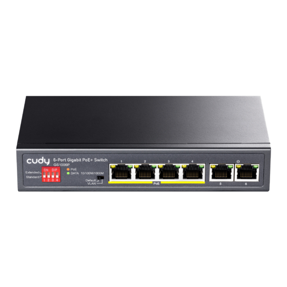
  • Seite 9: Led-Anzeige

    DIP Switch 1 Standart Modus Die Nummern 1-4 entsprechen PoE Port1 ~ Port4. In diesem Modus fungiert der PoE-Switch als allgemeiner Switch und alle PoE-Ports werden mit einer automatischen Aushandlung von 10/100 / 1000Mbps betrieben Modus erweitern In diesem Modus werden die PoE-Ports des PoE-Switch nur im 10-Mbit / s-Geschwindigkeits-Duplexmodus für die automatische Aushandlung betrieben.
  • Seite 10: Installation Des Switches

    Rückwand Auf der Rückseite des PoE-Schalters befinden sich eine Gleichstromsteckdose und eine Erdungssäule. Erdungssäule Die Erdungssäule befindet sich auf der linken Seite der Netzteilschnittstelle. Bitte verwenden Sie eine Erdung, um Blitzeinschläge zu vermeiden. Installation des Switches In diesem Teil wird beschrieben, wie Sie Ihren Ethernet-Switch installieren und Verbindungen herstellen. Befolgen Sie die folgenden Anweisungen, um eine fehlerhafte Installation zu vermeiden, die zu Geräteschäden und Sicherheitsrisiken führt.
  • Seite 11 Desktop-Installation Installieren Sie den Switch auf einem Schreibtisch. Bringen Sie diese Dämpfungsgummifüße an der Unterseite an jeder Ecke des Switch an, falls es zu Vibrationen kommt. Sorgen Sie für ausreichende Belüftung zwischen dem Gerät und den umliegenden Gegenständen. Wandmontage Bei den ersten beiden feststehenden Schrauben an der Wand, wie in der folgenden Abbildung gezeigt, die beiden Schalter mit den festen Löchern und die Maschine glatt auf die Schraube richten - 4 -...
  • Seite 12: Spezifikationen

    Schalten Sie den Schalter ein Schließen Sie das Gleichstromkabel an der Rückseite des Schalters und an eine Steckdose an (vorzugsweise eine geerdete). Wenn der Schalter eingeschaltet ist, blinken die LED-Anzeigen kurz für eine Sekunde, was ein Zurücksetzen des Systems darstellt. Die Power-LED leuchtet grün. Hinweis: Vergewissern Sie sich vor dem Einschalten, dass die Spannung korrekt ist, da sonst der Schalter beschädigt wird.
  • Seite 13 Guía del usuario 4-Port Gigabit+2GE PoE Switch...
  • Seite 14 contenidos del paquete Compruebe los siguientes contenidos de su paquete: PoE Switch x 1  User Guide x1  Power Adapter x1  Power Cord x 1  Accessories(Rubber Feet*4)  Si alguna parte se pierde y se daña, comuníquese con su agente local inmediatamente. Introducción El conmutador 4GE (PoE)...
  • Seite 15: Indicador Led

    DIP Switch 1 Modo estandar Los números 1-4 corresponden a PoE Port1 ~ Port4. Este modo hace que el conmutador PoE funcione como un conmutador general y todos los puertos PoE operen a 10/100 / 1000Mbps autonegociación Modo de extension Este modo hace que los puertos PoE del conmutador PoE funcionen solo en modo dúplex de 10Mbps de negociación automática, pero la distancia de entrega de la energía PoE y los datos de red pueden alcanzar los 200 m...
  • Seite 16: Panel Trasero

    Panel trasero El panel posterior del interruptor PoE indica una toma de corriente de entrada de CC y una columna de conexión a tierra. Columna de puesta a tierra La columna de conexión a tierra se encuentra en el lado izquierdo de la interfaz de la fuente de alimentación. Utilice una conexión a tierra de cables para evitar rayos.
  • Seite 17 Instalación de escritorio Instale el Interruptor en una computadora de escritorio, coloque estos pies de goma amortiguadores provistos en la parte inferior en cada esquina del Interruptor en caso de vibración externa. Deje un espacio adecuado para la ventilación entre el dispositivo y los objetos que lo rodean. Instalación de pared En los dos primeros tornillos fijos en la pared, como se muestra en la figura a continuación, apunte a los dos interruptores de orificio fijo y la máquina suavemente sobre el tornillo...
  • Seite 18 Encender el interruptor Conecte el cable de alimentación de CC a la parte posterior del interruptor y a una toma eléctrica (preferiblemente una que esté conectada a tierra). Cuando el interruptor está encendido, los indicadores LED parpadean momentáneamente durante un segundo, lo que representa un reinicio del sistema. El indicador LED de encendido se ilumina en verde.
  • Seite 19 Mode d'emploi 4-Port Gigabit+2GE PoE Switch...
  • Seite 20: Contenu Du Colis

    Contenu du colis Vérifiez le contenu suivant de votre colis: PoE Switch x 1  User Guide x1  Power Adapter x1  Power Cord x 1  Accessories(Rubber Feet*4)  Si une pièce est perdue ou endommagée, veuillez contacter votre agent local immédiatement. Introduction Le commutateur 4GE (PoE + 2GE est un commutateur de liaison montante rapide qui vous offre une mise à...
  • Seite 21: Mode Standard

    DIP Switch 1 Mode standard Les numéros 1 à 4 correspondent aux ports PoE 1 à 4. Ce mode fait en sorte que le commutateur PoE fonctionne comme un commutateur général et que tous les ports PoE fonctionnent à une négociation automatique de 10/100 / 1000Mbps. Mode étendu Ce mode permet aux ports PoE du commutateur PoE de fonctionner uniquement en mode duplex à...
  • Seite 22: Panneau Arrière

    Panneau arrière Le panneau arrière du commutateur PoE indique une prise d'alimentation CC et une colonne de mise à la terre. Colonne de terre La colonne de mise à la terre se trouve à gauche de l'interface d'alimentation. Veuillez utiliser un fil de terre pour éviter la foudre.
  • Seite 23 Installation de bureau Installez le commutateur sur un bureau, veuillez fixer les pieds en caoutchouc d’amortissement fournis au bas de chaque coin du commutateur en cas de vibrations externes. Prévoyez un espace suffisant pour la ventilation entre l'appareil et les objets qui l'entourent. Installation murale Dans les deux premières vis fixées au mur, comme indiqué...
  • Seite 24 Allumer l'interrupteur Veuillez brancher le cordon d’alimentation en courant continu à l’arrière de l’interrupteur et à une prise électrique (de préférence à la terre). Lorsque l'interrupteur est sous tension, les voyants clignotent momentanément pendant une seconde, ce qui représente une réinitialisation du système. Le voyant d'alimentation s'allume en vert.
  • Seite 25 Guida utente 4-Port Gigabit+2GE PoE Switch...
  • Seite 26: Contenuto Della Confezione

    Contenuto della confezione Controlla i seguenti contenuti del tuo pacchetto: PoE Switch x 1  User Guide x1  Power Adapter x1  Power Cord x 1  Accessories(Rubber Feet*4)  Se una parte è persa e danneggiata, contattare immediatamente il proprio agente locale. introduzione Switch 4GE (PoE) + 2GE Switch Fast uplink Switch che fornisce un upgrade ad alte prestazioni, a basso costo, facile da usare, senza interruzioni e standard per aumentare la vecchia rete a 1000 Mbps.
  • Seite 27: Modalità Standard

    DIP Switch 1 Modalità standard I numeri 1-4 corrispondono a PoE Port1 ~ Port4. Questa modalità fa funzionare lo switch PoE come uno switch generale e tutte le porte PoE funzionano con la negoziazione automatica 10/100 / 1000Mbps Estendi la modalità Questa modalità...
  • Seite 28 Pannello posterior Il pannello posteriore dell'interruttore PoE indica una presa di alimentazione in ingresso CC e una colonna di messa a terra. Colonna di messa a terra La colonna di messa a terra si trova sul lato sinistro dell'interfaccia dell'alimentatore. Si prega di utilizzare la messa a terra del filo per prevenire fulmini.
  • Seite 29 Installazione desktop Installare l'interruttore su un desktop, si prega di collegare questi piedini in gomma di imbottitura forniti sul fondo in ogni angolo dello switch in caso di vibrazione esterna. Lasciare uno spazio adeguato per la ventilazione tra il dispositivo e gli oggetti circostanti. Installazione a parete Nelle prime due viti fisse sul muro come mostrato nella figura sotto Puntare ai due interruttori a foro fisso e la macchina senza intoppi sulla vite...
  • Seite 30: Specificazioni

    Accendi l'interruttore Si prega di collegare il cavo di alimentazione CC nella parte posteriore dell'interruttore e in una presa elettrica (preferibilmente una messa a terra). Quando l'interruttore è acceso, gli indicatori LED lampeggiano momentaneamente per un secondo, il che rappresenta un ripristino del sistema. L'indicatore LED di accensione si accende in verde.

Inhaltsverzeichnis