GE M-Pact Plus Installation Und Betriebsanleitung

Verwandte Anleitungen für GE M-Pact Plus


Inhaltszusammenfassung für GE M-Pact Plus
- Seite 1 GE Consumer & Industrial Power Protection M-Pact Plus Air Circuit Breakers Operating & Installation instructions Frame 1 & 2, up to 4000A GE imagination at work...
- Seite 2 BREAKER DIMENSIONS APPENDIX 1 General 1 General 1 General 1 General 1 General 1.1 Introduction 1.2 Quality Assurance 1.3 Options Check Sheet 1.4 Serial Number 1.5 Transportation & Storage 1.6 Safety Precautions 2 Pictur 2 Pictur 2 Pictur 2 Pictur 2 Picture e e e e 3 Specif 3 Specif...
-
Seite 3: Allgemein
Wa rtungsprozedur en. Leistungsschalter Typ MPACT dürfen nur von maintained by competent and properly authorised personnel.If further information kompetentem, und geschultem Personal installier t,betrieben und gewartet is required, concerning any aspect of operation or maintenance of ‘M-PACT PLUS’ werden. circuit breakers, please contact: GE Consumer & Industrial Werden weitere Informationen zum Betrieb oder zur Wartung benötigt, wenden... - Seite 4 Es wird empfohlen, dass die folgenden Maßnahmen in jede handlungsmäßige instructions to personnel concerned with the handling, operation or maintenance Instr uktionen für das mit Handhabung, Betrieb und Wartung beauftragtem of ‘M-PACT PLUS’ circuit breakers. Personal einbezogen werden. During operation this circuit breaker is connected to dangerous voltages. When Im Einsatz ist dieser Leistungsschalter an gefährliche Spannungen angeschlossen.
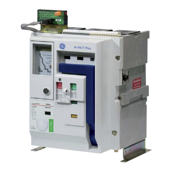
- Seite 5 BREAKER 2. Pictur 2. Pictur 2. Picture e e e e 2. Pictur 2. Pictur Legend: Legend: Legend: Legend: Legend: 1)Manual Charging handle. 1)Handspannhebel 2)Closing push button (ON). 2)EIN Drucktaster 3)Opening pushbutton (OFF). 3)AUS Dr ucktaste 4)Main contact position indicator. 4)Schaltstellungsanzeige 5)Charging spring status indication.
- Seite 6 BREAKER 3 Specif 3 Specif 3 Specify on the or y on the or y on the order y on the or 3 Specif 3 Specif y on the or SPECIFY ON THE ORDER T ype S ( 50 k A ) Type N ( 65kA ) T ype H ( 80kA ) 1 De vi ce...
- Seite 7 BREAKER 18 Co ntro l V olta ge F ram e 1&2 M O P UV TD 24/30V D C 48V DC 110/130V AC /DC 220/250V AC /DC 380/440V AC /DC (1)DC NA for UV TD (2)DC NA for UV /UV TD...
- Seite 8 Ausfahr technik geliefert .Zum Einbau des Einschubträgers muß zunächst der cassettes.Remove the breaker from its cassette using procedures described in Schalter entfernt w er den (Siehe hier zu Abschnitt: “Ausfahren des the section ‘Withdrawal of M-PACT Plus Circuit Break er’.Position the cassette Leistungsschalters”). as required in the switchboard.
-
Seite 9: Steuerleitungskontakte
• Allen key set various (Used for removal horizontal par t of spring charging handle to allow complete removal of M-PACT Plus front fascia and LT mounting bracket fixing scr ews). Fitting Instr... -
Seite 10: Einbau Mechanischer St T T T T Örmeldeschalter
BREAKER 6.1.6 This should be replaced once the L.T blocks have been replaced. For easier 6.1.6 Der Auslöser sowie ggf. der Kabelbinder müssen wieder eingebaut werden access, all ancillary devices (shunt trip, etc.) should be temporarily removed. nachdem der S teuerklemmblock ausgetauscht wurde. Anbaugeräte wie Arbeitsstromauslöser und Einschaltspule müssen vorrübergehend ausgebaut werden. - Seite 11 BREAKER 6.2.2 Loop wiring between electronic releases unit & alarm assy. Bracket 6.2.2 Kabel mit Flachsteckkontakten mit den Anschlüssen B7 und B8 der connect wires to LT-B7 & B8. Klemmblocke v erbinden. Das Kabel muss zwischen Auslösen und Störmeldeschalter verlegt werden. 6.2.3 Fit pad &...
- Seite 12 BREAKER 6.3.3 Feed cables through grommet in cassette side. (Wire to terminal blocks ` ` ` ` ` 6.3.3 Nun Die Kabel des Positionsmeldeschalters durch diese Öffnung führen. after setting C-Switch). (Anschluss an die Klemmblöcke nachdem der Meldeschalter montiert ist) 6.3.4 Position carriage switch over two tapped holes (see Fig.
- Seite 13 BREAKER 6.3.7 Place setting gauge into position shown and hold firmly against forward 6.3.7 Die Einstelllehre wie dargestellt positionieren und gegen das Einfahrgetriebe face of pusher. Adjust position of carriage switch until the upright drive face on drücken. Nun den Meldeschalter so verschieben das, der transparente Teil des the clear plastic moulding is just in contact with setting gauge.
- Seite 14 BREAKER 6.3.12 Cut a cable at a time. 6.3.12 Ein Kabel nach dem anderen auf Länge schneiden. 6.3.13 Fit terminal. 6.3.13 Krimpkontakt “aufkrimpen” 6.3.14 Fit the wires with corresponding numbers. 6.3.14 Kabel mit entsprechender Zuordung an die Leiste anschließen 6.3.15 Screw the terminal blocks to the side of the cassette. 6.3.15 Anschlussleiste anbauen 6.3.16 Kabel Positionieren 6.3.16 Position the wires...
- Seite 15 BREAKER 6.3.17 Kabel mit selbstklebenden halten und Kabelbindern fixieren. 6.3.17 Fit wires with cable ties and stickers. 6.3.18 Fit the circuit breaker and set it in disconnected position (green) 6.3.18 Leistungsschalter einsetzen in Trennstellung (Grün) 6.3.19 Check the wires with a tester: 6.3.19 Prüfen mit Durchgangsprüfer: 1-2 Open contact 1-2 Kein Durchgang...
-
Seite 16: Prüfen Mit Durchgangsprüfer
BREAKER 6.3.22 Check the wires with a tester: 6.3.22 Prüfen mit Durchgangsprüfer: 7-8 Open contact 7-8 Kein Durchgang 7-9 Closed contact. 7-9 Durchgang 10-11 Open contact. 10-11 Kein Durchgang 10-12 Closed contact. 10-12 Durchgang 6.3.23 Fit the circuit breaker and set it in connected position (red) 6.3.23 Schalter voll einfahren (Rot) 6.3.24 Check the wires with a tester: 6.3.24 Prüfen mit Durchgangsprüfer:... - Seite 17 4. The trip pins on the moulding are snapped in from its underside and can be pushed der Hand oder einem Schraubendrehen herausgedrückt werden. out using fingures or an appropriate screwdriver in the slot between the retaining 5. Die geänderte Funktionsweise kann nun durch wiedereinstecken der legs. Antriebsstößel an gewünschter Position eingestellt werden.
-
Seite 18: Betrieb
(Siehe Abbildung). Note, the carriage switch will maintain a disconnected indication even when the Hinweis: Der Meldeschalter behält die Trennpositionssignalisierung bei auch M-PACT Plus is fully withdrawn or removed. wenn der Leistungsschalter aus der Kassette entnommen wird. Trip Pin Betätigung 6.3.25 Carriage switch- how to make the NO/NC Conversion in the contact using... - Seite 19 BREAKER 6.4 Fitting Instr 6.4 Fitting Instr 6.4 Fitting Instr 6.4 Fitting Instr 6.4 Fitting Instruction uction uction uction uction - Electrical Accessories - Electrical Accessories - Electrical Accessories - Electrical Accessories - Electrical Accessories 6.4 Einbau Anleitung - elek Einbau Anleitung - elek Einbau Anleitung - elek Einbau Anleitung - elek...
-
Seite 20: Einschaltspule
BREAKER 6.5 Einschaltspule 6.5 Einschaltspule 6.5 Einschaltspule 6.5 Einschaltspule 6.5 Einschaltspule 6.5 Closing coil 6.5 Closing coil 6.5 Closing coil 6.5 Closing coil 6.5 Closing coil Die Einschaltspule wird ohne Befestigungsschrauben in die entsprechenden The closing coil is a clip on device and requires no fasteners. Mounting positions Öffnungen im Mechanismus eingeschnappt . - Seite 21 BREAKER 6.5.5 Connect closing coil flying leads into low tension auxiliary isolating con- 6.5.5 Danach die Einschaltspule elektrisch an Klemmblock B13 und B 14 tact terminals B13 and B14 as per schematic diagram, observing polarity mark- anschließen. Auf Polung für DC Variante achten. ings on DC versions.
- Seite 22 BREAKER Shunt trip coil Shunt trip coil Arbeitsstr Arbeitsstr omauslöser omauslöser Shunt trip coil Shunt trip coil Shunt trip coil 6.6 Arbeitsstr Arbeitsstr Arbeitsstromauslöser omauslöser omauslöser The shunt trip coil is a clip on device and requires no fasteners. Mounting positions Der Arbeitsstromauslöser wird ohne Befestigungsschrauben in die of the three units (closing coil, shunt trip coil and undervoltage release) are not entsprechenden Öffnungen im Mechanismus eingeschnappt .
- Seite 23 BREAKER 6.6.6 The front facia must now be replaced in the reverse order to the removal.The 6.6.6 Jetzt müssen der Deckel und der Handspannhebel wieder angebaut werden. shunt trip coil is now is fitted and ready for testing Jetzt ist der Arbeitsstromauslöser bereit um eine Funktionsprüfung durchzuführen.
- Seite 24 BREAKER 6.7.3Die Unterspannungsauslöserspule nach vorne geneigt in einer Hand haltend 6.7.3 Holding undervoltage release coil in one hand tilt the unit forward, engage in die vorderen Befestigungsschlitze einführen. front hooks into top support plate. 6.7.4 Nun die Spule nach hinten drehen bis die Schnapphaken greifen. 6.7.4 Tilt backwards until the rear hooks engage in the slots and press down into position.
- Seite 25 BREAKER 10 11 13 14 15 16 (View fr (View fr (View fr (View fr (View from fr om fr om fr om fr om front side of br ont side of br ont side of br ont side of br ont side of break eaker after r er after r...
- Seite 26 BREAKER 6.9 SPECIAL FEATURE 6.9 SPEZIELLES ZUBEHÖR 6.9.1 Prop open feature (For use by trained personnel) 6.9.1 Berührungsschutzabdeckung – Inspektion der Einfahrkontakte – To inspect the main fixed contacts each shutter (or both) may be propped Nur für geschultes Personal open.
- Seite 27 BREAKER 6.9.3 Safety shutters Security padlocking 6.9.3 Berührungsschutzabdeckung - Sicherheitsverriegelung 6.9.3.1 Fasteners Fixing Plate Elastic Rings Befestigungsplatte Elastische Scheiben Fixing Nuts Key Lock Bar Befestigungsmuttern Zylinderschloss Brass spacing ring, block Positioners lever, fixing nut Positionierungsscheiben Messing Distanzring, Blockierhebel, Befestigungsmutter 6.9.3.2 Remove the front cover by, unscrewing the fixing screws. 6.9.3.2 Frontabdeckung abbauen (Befestigungsschrauben lösen) 6.9.3.3 Unscrew the nut(C) on the top of the black tube and remove it from the 6.9.3.3 Mutter oben auf(C) dem Handkurbelhalterrohr entfernen und das Rohr...
- Seite 28 BREAKER 6.9.3.5 Locate support plate (A) over the pre-existing nuts and fix the provided 6.9.3.5 Nun Befestigungsplatte (A) auf die Bolzen (siehe 9) anbauen und die rods with elastic rings (B). Fixing point of the rods with elastic rings. mitgelieferten Verriegelungshebel mit den Elastischen Scheiben (B) montieren 6.9.3.6 Locate the lever in front of the pin.
- Seite 29 BREAKER 6.9.3.10 Locate the positioners (E) in their place. 6.9.3.10 Positionierungsscheiben(E) einsetzen 6.9.3.11 Fasten the front cover with screw, reset the rods and make sure they 6.9.3.11 Frontabdeckung wieder anschrauben, gleichzeitig sicherstellen das slide freely. die Verriegelungshebel sich frei bewegen lassen 6.9.3.12 Locate the brass spacing ring and the block lever, and screw the 6.9.3.12 Messing Distanzring, Blockierhebel einsetzen und mit der(F) fixing nut(F) of the key lock (D).
-
Seite 30: Türverrriegelung
BREAKER 6.10 Door interlocking 6.10 Türverrriegelung A door interlock mechanism may be fitted inside the cassette on the right for Eine Türverriegelung kann innen in der Kassette rechts für links anschlagen L/H hinged door (see in figure) or left for R/H hinged door. Türen und link für rechts anschlagen Türen eingebaut werden. -
Seite 31: Einbau Türverriegelung
BREAKER 6.10.2 Einbau Türverriegelung 6.10.2 To fit Door Interlock Eine Türverriegelung kann innen in der Kassette rechts für A door interlock mechanism may be fitted inside the cassette on the right for links angeschlagene Türen bzw. links für rechts L/H hinged door or left for R/H hinged door. Specify whether door is L/ H or R/ angeschlagene Türen eingebaut werden. - Seite 32 BREAKER Door bracket location detail below (Fig.) is for right hand hinged switch board Türwinkel (siehe Fig.) dargestellt für Tür mit Linksanschlag. Zwei Löcher für doors. Drill two holes in the door for M5 clearance. M5 Befestigungsmaterial müssen gebohrt werden. 21mm 21mm 21mm...
-
Seite 33: Schaltspielzähler
BREAKER To earth the lower terminal set: Erdung der unteren Anschlüsse: a)Remove lower cluster contacts, reverse the earthing bar so that the M10 a) Entfernen der unteren Ausfahrkontakte, Erdungsschiene umdrehen, so dass tapped holes point downwards, apply bolts and washers as above. die M10 Gewindelöcher nach unten zeigen. - Seite 34 Prüfen das mit herausgezogener Verriegelung die handkurbel nicht gesteckt werden kann Prüfen das mit herausgezogener Verriegelung die Berührungsschutzabdeckungen nicht Verriegelung safety shutter geöffnet werden können Prüfen das der Leistungsschalter sich nicht zuschalten läst wenn der entsprechende Bouwdenzug Verriegelung zwischen Schaltern Bouwdenzug betätigt ist.
-
Seite 35: Wartung
BREAKER 8 Maintenance 8 Wartung: Scope and intervals of testing are to be determined in accordance with the Wartungsinterwalle und Wartungstiefe sind abhängig vom Grad der degree of utilization of the circuit breaker. For ensuring service reliability Benutzung des Leistungsschalters. Um eine dauernde Einsatzbereitschaft and constant readiness for operation it is recommended to observe the zu gewähren, sollten alle Wartungen fristgerecht durchgeführt werden. - Seite 36 Defective kinematic motion Contact GE Consumer & Industrial (page 36) Measure the power supply voltage: it must be between 0.7Vn and 1.1Vn forcurrent launching The opening bobbin power supply voltage is bobbins and between 0.35Vn and 0.70Vn for...
- Seite 37 BREAKER Schalter öffent nicht manuell Schalter öffent nicht mit Arbeitsstromauslöser oder Unterspannungsauslöser Schalter schaltet manuell nicht ein Schalter schaltet elektrisch (Einschaltspule) nicht ein Schalter schließt nicht, oder schließt aber öffnet sofort wieder, oder schließt aber öffnet nach kurzer Zeit wieder. Schalter läßt sich nicht oder nur schwer einfahren Schalter läßt sich nicht ausfahren Motor spannt die Federn nicht...
- Seite 38 However, the information contained in this document is subject to change without notice, and does not represent a commitment on the part of General Electric Company. The GE monogram is a registered trademark of General Electric Company.
- Seite 39 BREAKER DIMENSIONS APPENDIX 1 General (E 1 General (E 1 General (E 1 General (E 1 General (ETU) Introduction 1.2 There are three types of Electronic Trip Unit (E TU) 1.3 Functional Features Terminolog y (APPENDIX -G ) 2 Pictur 2 Pictur 2 Picture(M-PR e(M-PR...
- Seite 40 1 General (E 1 General (E 1 General (ETU) 1 Allgemein (E 1 Allgemein (E 1 Allgemein (E TU) 1 General (E 1 General (E 1 Allgemein (E 1 Allgemein (E 1.1 Intr 1.1 Intr 1.1 Intr 1.1 Intr 1.1 Introduction oduction oduction oduction...
- Seite 41 2 Pictur 2 Pictur 2 Picture(M-PR e(M-PR e(M-PR e(M-PR OPL OPLUS) 2 Pictur 2 Pictur e(M-PR 1 1 1 5 5 5 6 6 6 2 2 2 7 7 7 8 8 8 3 3 3 9 9 9 4 4 4 Example - M-PR Example - M-PR...
-
Seite 42: Bedienelemente
3 Operator Contr 3 Operator Contr 3 Operator Contr 3 Operator Contr 3 Operator Controls 3 Bedienelemente 3 Bedienelemente 3 Bedienelemente 3 Bedienelemente 3 Bedienelemente All operator controls are pr esented on the M-PRO Plus fr ont panel. The switches Alle Bedienelemente sind auf der Frontplatte des MPRO Plus leicht zugänglich may be adjusted at any time, whether the breaker is open or closed, and powered angebracht . - Seite 43 3.4 Instantaneous pr 3.4 Instantaneous pr otection otection Unver er er er er zöger zöger zöger ter K ter K ter Ku r u r u r u r u rzschlussschutz zschlussschutz zschlussschutz 3.4 Instantaneous pr 3.4 Instantaneous pr 3.4 Instantaneous protection otection otection 3.4 Unv...
-
Seite 44: Rückstellung
3.7 Rückstellung 3.7 Rückstellung 3.7 Rückstellung 3.7 Rückstellung 3.7 Rückstellung 3.7 R 3.7 R 3.7 R 3.7 R 3.7 Reset eset eset eset eset In the event of a fault , the M-PRO 17+ will trip the breaker and the reset button will Im Fehlerfall löst der M-PRO den Leistungsschalter aus und der Rückstellknopf eject from its normally flush position. - Seite 45 4 Pictur 4 Pictur 4 Picture(M-PR e(M-PR e(M-PR e(M-PRO) O) O) O) O) 4 Mpr 4 Mpro Einführ 4 Mpr o Einführ o Einführ o Einführung 4 Pictur 4 Pictur e(M-PR 4 Mpr 4 Mpr o Einführ The user interface on the panel M-PRO 30/40 unit is used for operator control Die Bedienelemente auf dem Auslöser ermöglichen die Einstellung der Parameter.
-
Seite 46: Button Operation
5 Operator Contr 5 Operator Contr 5 Operator Control ol ol ol ol 5 Menüführ 5 Menüführ 5 Menüführung 5 Operator Contr 5 Operator Contr 5 Menüführ 5 Menüführ 5.1 Button Operation 5.1 Button Operation 5.1 Button Operation 5.1 Button Operation 5.1 Button Operation 5.1 T 5.1 T... - Seite 47 5.1.3 5.1.3 Shor Shor t time settings (Fixed) t time settings (Fixed) 5.1.3 K 5.1.3 K 5.1.3 Ku r u r u r u r u rzzeitschutz (K zzeitschutz (K zzeitschutz (K zzeitschutz (Ku r u r u r u r u rzschlussschutz) (Fest) zschlussschutz) (Fest) zschlussschutz) (Fest) 5.1.3...
- Seite 48 5.2 Menu S 5.2 Menu S 5.2 Menu S 5.2 Menu S 5.2 Menu Str tr tr tr tructur uctur uctur uctur ucture e e e e There are four levels within the M-PRO menu structure, the main three are described below. Only those menus specified at the time of ordering will be factory set into M-PRO hence not all of the following menus will be available.
- Seite 49 5.2 Menüstr 5.2 Menüstr 5.2 Menüstr 5.2 Menüstr 5.2 Menüstruk uktur Innerhalb der Menüstruktur existieren vier Ebenen. Die Hauptebenen sind unten beschrieben. Nur die bestellten Menüs werden werksseitig im M-PR O gespeichert, desw egen sind nicht alle der folgenden Menüs vorhanden. Me nü...
- Seite 50 Operating M-PR Operating M-PR O30/40 O30/40 Operating M-PR Operating M-PR Operating M-PRO30/40 O30/40 O30/40 When M-PRO is first energised: The green ‘Healthy’ LED will light indicating that (a) power is present, (b) The unit is functioning normally. This will remain lit at all times when M-PRO is energised unless a fault is present .
- Seite 51 Bedienung M-PR Bedienung M-PR Bedienung M-PRO30/40 O30/40 O30/40 O30/40 Bedienung M-PR Bedienung M-PR O30/40 Wir d der M-PRO erstmalig in Betrieb genommen: leuchtet die grüne Betriebsbereitschafts-LED und zeigt an, dass (a) der Auslöser mit Energie versorgt wird und (b) fehlerfrei arbeitet . Diese LED leuchtet, solange der M-PRO an Spannung liegt, außer es tritt ein Fehler auf.
- Seite 52 S/C Cur S/C Cur S/C Cur S/C Cur S/C Curv v v v v e e e e e =C03, 69ms @ 6 Iset =C03, 69ms @ 6 Iset =C03, 69ms @ 6 Iset =C03, 69ms @ 6 Iset =C03, 69ms @ 6 Iset Fixed S/C Crnt Fixed S/C Crnt Fixed S/C Crnt...
- Seite 53 S/C Cur S/C Cur S/C Curv v v v v e e e e e S/C Cur S/C Cur =C03, 69ms @ 6 Iset =C03, 69ms @ 6 Iset =C03, 69ms @ 6 Iset =C03, 69ms @ 6 Iset =C03, 69ms @ 6 Iset Fixed S/C Crnt Fixed S/C Crnt Fixed S/C Crnt...
-
Seite 54: Einleitung
6 Pr 6 Pr 6 Protection otection otection otection 6 Schutz 6 Schutz 6 Schutz 6 Pr 6 Pr otection 6 Schutz 6 Schutz 6.1 Einleitung 6.1 Einleitung 6.1 Einleitung 6.1 Einleitung 6.1 Einleitung Earth F th F th F th Fault Pr ault Pr ault Pr... - Seite 55 The neutral measurement device recommended for unrestricted earth fault Für die Messung des Neutralleiterstromes muss eine Rogowski Spule benutzt protection is a Rogowski coil. If a 4-pole break er is used this device will be werden die baugleich mit den internen Spulen ist. In einem 4 pol Schalter ist mounted on the breaker, if a 3-pole breaker is used on a 4-wire system, the device diese Spule bereits eingebaut , für einen 3 pol Schalter in einem Vierleiter Netz will be mounted remote from the breaker, but within the cubicle, using a Rogowski...
- Seite 56 Figur Figur e 5 - S e 5 - S tandby ear tandby ear th fault curr th fault curr ents ents Figur Figur e 5 - Beidseitiger Er e 5 - Beidseitiger Er dschlussschutz dschlussschutz Figur Figur Figure 5 - S e 5 - S e 5 - Standby ear tandby ear...
- Seite 57 P r P r P r P r P rotection otection otection otection otection Dieses sieht wie folgt aus. P r P r P r P r P rotection otection otection Earth Protection otection otection Earthprotection REF Current Eingangsseitiger Erdschlussstrom UEF Current Abgangsseitiger Erdschlussstrom UEF Trip Time...
- Seite 58 (power box, APU or test box). eine Veränder ung der Parameter v orgenommen werden. Zum Ändern solcher NOTE:- If Auxiliary Power supply is not used Einstellungen muss der Schalter geöffnet sein, daher ist eine externe Spannungsversorgung notwendig (z.B. Testgerät).
-
Seite 59: Für M-Proplus / M-Pr
7.3 T 7.3 T est Connector & T est Connector & T est bo est bo est bo x x x x x 7.3 S 7.3 S tecksock tecksock el und T el und T gerät gerät 7.3 T 7.3 T 7.3 Test Connector &... -
Seite 60: Anschlüsse
The coil should be positioned with the arrow facing the direction as defined im Applikationshinweis APP001 zu finden, erhältlich bei GE Pow er Controls. Die below. The end connector s marked +ve and -ve should be terminated at the A Spule ist so zu positionier en, dass der Pfeil in die unten angegebene Richtung block. -
Seite 61: Rogowskispule Für Neutralleiter
Verhalten des Mpro beeinflussen können. 5. The 2m extension lead should next be plugged into the neutral Rogowski coil flying lead and routed back to the M-PACT Plus. The end connectors marked +ve and –ve should be terminated at the UME in-line with connections shown on the following figures. - Seite 62 Illustration of frame 2 neutral Rogowski coil se- Abbildung Rogowskispule Baugröß e 2 cured onto mounting bracket 3 off bars at 6.3mm fixier t auf Montageklammern auf 3 x 40mm. Kupferschienen 6,3 x 40 mm Rogowski coil secured onto mounting bracket Rogowskispule mit Kabelbinder auf with cable ties, coil positioned centrally on Montageklammer, Spule zentral...
- Seite 63 Abbildung Neutralleiter Rogowskispule Einbauposition und Richtung für plications where busbars connected to top terminals and cables connected to Anwendungen mit Schienenanschluss auf der Einspeiseseite und Kabeln auf der bottom terminals of M-PACT Plus Abgangsseite. Diagram illustrating neutral Rogowski coil fixing position and direction for appli- Abbildung Neutralleiter Rogowskispule Einbauposition und Richtung für...
- Seite 64 E i ng än g e ge schl o ssen si n d, o hn e d ass e in Si g na l a nl i eg t. • E xte rn e R og owski spu l e n ich twa y vor schr iftsmä ßi g •...
- Seite 65 DIMENSIONS...
- Seite 66 DIMENSIONS...
- Seite 67 DIMENSIONS...
- Seite 68 DIMENSIONS...
- Seite 69 DIMENSIONS...
- Seite 70 DIMENSIONS...
- Seite 71 DIMENSIONS...
- Seite 72 DIMENSIONS...
- Seite 73 DIMENSIONS...
- Seite 74 DIMENSIONS...
- Seite 75 DIMENSIONS...
- Seite 76 DIMENSIONS...
- Seite 77 DIMENSIONS...
- Seite 78 DIMENSIONS...
- Seite 79 DIMENSIONS...
- Seite 80 DIMENSIONS...
- Seite 81 DIMENSIONS...
- Seite 82 DIMENSIONS...
- Seite 83 DIMENSIONS...
- Seite 84 DIMENSIONS...
- Seite 85 DIMENSIONS...
- Seite 86 DIMENSIONS...
- Seite 87 DIMENSIONS...
- Seite 88 DIMENSIONS...
- Seite 89 DIMENSIONS...
- Seite 90 DIMENSIONS...
- Seite 91 DIMENSIONS...
- Seite 92 DIMENSIONS...
- Seite 93 DIMENSIONS...
- Seite 94 DIMENSIONS...
- Seite 95 DIMENSIONS...
- Seite 96 DIMENSIONS - 3200A - 3200A...
- Seite 97 DIMENSIONS - 3200A - 3200A...
- Seite 98 DIMENSIONS - 3200A - 3200A...
- Seite 99 DIMENSIONS - 3200A - 3200A...
- Seite 108 - 3200 - 3200...
- Seite 110 800 to 3200 4000 (1) Height (H) is from mounting surface to highest part of the M-PACT Plus (2) Depth (D) is from the cubicle door to the rear moulding 3) Length (L) is distance between widest part of the breaker...
- Seite 111 DIMENSIONS Weight and Dimension Weight and Dimension Weight and Dimension Weight and Dimension Weight and Dimension Gewichte (Kg) S Reihe N Reihe H Reihe Festeinbau ACB 3 Pole 4 Pole 3 Pole 4 Pole 3 Pole 4 Pole Baugröße 400 bis1600A 2000 bis 2500A 800 bis 3200A 4000A...
- Seite 112 DIMENSIONS W W W W W iring M-PR iring M-PR iring M-PR iring M-PRO O O O O iring M-PR...
- Seite 113 APPENDIX Anschlussdiagramme Anschlussdiagramme Anschlussdiagramme Anschlussdiagramme Anschlussdiagramme Baugr Baugr Baugr Baugr Baugröß öß öß öß öße 1 & 2 (3 & 4 polig) e 1 & 2 (3 & 4 polig) e 1 & 2 (3 & 4 polig) e 1 & 2 (3 & 4 polig) e 1 &...
- Seite 114 APPENDIX W W W W W iring Diagram iring Diagram iring Diagram iring Diagram iring Diagram M-pr M-pr M-pr M-pr M-pro 30/40 o 30/40 o 30/40 o 30/40 o 30/40...
- Seite 115 APPENDIX Anschlussdiagramme Anschlussdiagramme Anschlussdiagramme Anschlussdiagramme Anschlussdiagramme M-PR M-PR M-PR M-PR M-PRO 30/40 O 30/40 O 30/40 O 30/40 O 30/40 serielle Schnittstelle serielle Schnittstelle serielle Schnittstelle serielle Schnittstelle serielle Schnittstelle...
- Seite 116 APPENDIX...
- Seite 117 APPENDIX APPENDIX - A APPENDIX - A APPENDIX - A APPENDIX - A APPENDIX - A Trip Cur Trip Cur Trip Cur Trip Cur Trip Curv v v v v es* MPro Plus - Frame1 & Frame2 o Plus - Frame1 & Frame2 o Plus - Frame1 &...
- Seite 118 APPENDIX Anhang A Anhang A Anhang A Anhang A Anhang A Auslösek Auslösek Auslösek Auslösek Auslösekennlinien * ennlinien * ennlinien * ennlinien * ennlinien * Mpro Plus für Baugr o Plus für Baugr o Plus für Baugr o Plus für Baugr o Plus für Baugröß...
- Seite 119 APPENDIX APPENDIX - B APPENDIX - B APPENDIX - B APPENDIX - B APPENDIX - B Trip Cur Trip Cur Trip Curv v v v v es* Trip Cur Trip Cur MPro Plus - Frame1 & Frame2 o Plus - Frame1 & Frame2 o Plus - Frame1 &...
- Seite 120 APPENDIX Anhang B Anhang B Anhang B Anhang B Anhang B Auslösek Auslösek Auslösekennlinien * Auslösek Auslösek ennlinien * ennlinien * ennlinien * ennlinien * Mpro Plus für Baugr o Plus für Baugr o Plus für Baugr o Plus für Baugr o Plus für Baugröß...
- Seite 121 APPENDIX APPENDIX - C APPENDIX - C APPENDIX - C APPENDIX - C APPENDIX - C Trip Cur Trip Cur Trip Cur Trip Cur Trip Curv v v v v es* Mpro 30 / 40 with tolerance o 30 / 40 with tolerance o 30 / 40 with tolerance o 30 / 40 with tolerance o 30 / 40 with tolerance...
- Seite 122 APPENDIX Anhang C Anhang C Anhang C Anhang C Anhang C Auslösek Auslösek Auslösekennlinien* Auslösek Auslösek ennlinien* ennlinien* ennlinien* ennlinien* Mpro 30/40 o 30/40 o 30/40 o 30/40 o 30/40 LT mit 1x Schalt e rnennstrom (IN) LT set at 1 x ACB rating (In) LTD mit 35 s LTD s et at 35 s SC mit 6 x Ir...
- Seite 123 APPENDIX APPENDIX - D APPENDIX - D APPENDIX - D APPENDIX - D APPENDIX - D Trip Cur Trip Cur Trip Cur Trip Cur Trip Curv v v v v es* Mpro 30 / 40 without tolerance o 30 / 40 without tolerance o 30 / 40 without tolerance o 30 / 40 without tolerance o 30 / 40 without tolerance...
- Seite 124 APPENDIX Anhang D Anhang D Anhang D Anhang D Anhang D Auslösek Auslösek Auslösek Auslösek Auslösekennlinien* ennlinien* ennlinien* ennlinien* ennlinien* Mpro 30/40 o 30/40 o 30/40 o 30/40 o 30/40 * Überlast und Verzögerter Kurzschluss bei Ir= 1x In ** N= I/Ir für Überlast und Kurzschluss N= I/In für Unverzögerten Kurzschlussschutz and Erdschluss...
- Seite 125 APPENDIX...
- Seite 126 APPENDIX Long Time Pr Long Time Pr otection Cur otection Cur otection Curv v v v v es es es es es Long Time Pr Long Time Pr Long Time Protection Cur otection Cur M-PRO 30/40 MOTOR PROTECTION Long Time Protection M-PRO 20/30/40 STANDARD INVERSE Long Time Protection 10000 1000...
- Seite 127 APPENDIX APPENDIX - E APPENDIX - E APPENDIX - E APPENDIX - E APPENDIX - E Trip Cur Trip Cur Trip Curv v v v v es* Trip Cur Trip Cur Mpro 30 / 40 with tolerance o 30 / 40 with tolerance o 30 / 40 with tolerance o 30 / 40 with tolerance o 30 / 40 with tolerance...
- Seite 128 APPENDIX Anhang E Anhang E Anhang E Anhang E Anhang E Er Er Er Er Erdschluss K dschluss K dschluss K dschluss K dschluss Kur ur ur ur urv v v v v en* (Mit T (Mit T (Mit Toleranzband) (Mit T (Mit T oleranzband)
- Seite 129 APPENDIX APPENDIX - F APPENDIX - F APPENDIX - F APPENDIX - F APPENDIX - F Trip Cur Trip Cur Trip Cur Trip Cur Trip Curv v v v v es* Mpro 30 / 40 without tolerance o 30 / 40 without tolerance o 30 / 40 without tolerance o 30 / 40 without tolerance o 30 / 40 without tolerance...
- Seite 130 APPENDIX Anhang F Anhang F Anhang F Anhang F Anhang F Er Er Er Er Erdschluss K dschluss K dschluss K dschluss K dschluss Kur ur ur ur urv v v v v en* (Mit T (Mit T (Mit Toleranzband) (Mit T (Mit T oleranzband)
-
Seite 131: Anhang
APPENDIX APPENDIX - G APPENDIX - G APPENDIX - G APPENDIX - G APPENDIX - G Anhang Anhang Anhang Anhang Anhang - G T T T T T erminolog erminolog erminolog erminolog erminology y y y y Abkür Abkür Abkür Abkür Abkürzungen zungen... - Seite 132 APPENDIX APPENDIX -H APPENDIX -H APPENDIX -H APPENDIX -H APPENDIX -H Anhang -H Anhang -H Anhang -H Anhang -H Anhang -H R R R R R ecommended T ecommended T ecommended T ecommended Tool Kit for Maintenance and ecommended T ool Kit for Maintenance and ool Kit for Maintenance and ool Kit for Maintenance and...
- Seite 133 APPENDIX APPENDIX-K(O APPENDIX-K(O APPENDIX-K(O APPENDIX-K(O APPENDIX-K(Ov v v v v er View - Special Featur er View - Special Featur er View - Special Featur er View - Special Featur er View - Special Features) M-PRO Microprocessor Protection Relays - Specifictions Trip Unit MPRO 17Plus* MPRO 18Plus*...
- Seite 134 APPENDIX APPENDIX-K(O APPENDIX-K(O APPENDIX-K(O APPENDIX-K(O APPENDIX-K(Ov v v v v er View - Special Featur er View - Special Featur er View - Special Featur er View - Special Features) er View - Special Featur M-PRO Microprocessor Protection Relays - Spezifikation Trip Unit MPRO 30 MPRO 40...
- Seite 135 APPENDIX The Policy of GE Consumer & Industrial is one of continuous Improvement.The right The Policy of GE Consumer & Industrial is one of continuous Improvement.The right is reserved to alter the design or any structural details of the products at any time...