HomeMatic HMW-Sys-Tm-DR Installations- Und Bedienungsanleitung
Rs485 busabschluss-widerstand
Vorschau ausblenden
Andere Handbücher für HMW-Sys-Tm-DR:
- Installations- und bedienungsanleitung (24 Seiten)
Inhaltsverzeichnis
Werbung
Verfügbare Sprachen
Verfügbare Sprachen
Quicklinks
Installations- und Bedienungsanleitung
D
RS485 Busabschluss-Widerstand
HMW-Sys-Tm
RS485 Busabschluss-Widerstand
Hutschienenmontage
HMW-Sys-Tm-DR
Seite 4 - 12
GB
Installation and Operating Manual
RS485 bus terminator
HMW-Sys-Tm
RS485 bus terminator
for mounting on DIN rails
HMW-Sys-Tm-DR
Page 14 - 22
Werbung
Kapitel
Inhaltsverzeichnis

Verwandte Anleitungen für HomeMatic HMW-Sys-Tm-DR


Inhaltszusammenfassung für HomeMatic HMW-Sys-Tm-DR
- Seite 1 Installations- und Bedienungsanleitung RS485 Busabschluss-Widerstand HMW-Sys-Tm RS485 Busabschluss-Widerstand Hutschienenmontage HMW-Sys-Tm-DR Seite 4 - 12 Installation and Operating Manual RS485 bus terminator HMW-Sys-Tm RS485 bus terminator for mounting on DIN rails HMW-Sys-Tm-DR Page 14 - 22...
- Seite 2 1. Ausgabe Deutsch 07/2007 Dokumentation © 2007 eQ-3 Ltd., Hong Kong Alle Rechte vorbehalten. Ohne schriftliche Zustimmung des Herausgebers darf dieses Handbuch auch nicht auszugsweise in irgendeiner Form reproduziert werden oder unter Verwendung elektronischer, mechanischer oder chemischer Verfahren vervielfältigt oder verarbeitet werden. Es ist möglich, dass das vorliegende Handbuch noch drucktechnische Mängel oder Druckfehler aufweist.
- Seite 3 1. English edition 07/2007 Documentation © 2007 eQ-3 Ltd., Hong Kong All rights reserved. No parts of this manual may be reproduced or processed in any form using electronic, mechanical or chemical processes in part or in full without the prior explicit written permission of the publisher.
-
Seite 4: Inhaltsverzeichnis
Allgemeine Systeminformation zu HomeMatic ......9 Installation ......9 Wartung und Reinigung . -
Seite 5: Hinweise Zu Dieser Anleitung
Hinweise zu dieser Anleitung Lesen Sie diese Anleitung sorgfältig, bevor Sie ihre HomeMatic Komponenten in Betrieb nehmen. Bewahren Sie die Anleitung zum späteren Nachschlagen auf! Wenn Sie das Gerät anderen Personen zur Nutzung überlassen, übergeben Sie auch diese Bedienungsanleitung. Benutzte Symbole: Achtung! Hier wird auf eine Gefahr hingewiesen. -
Seite 6: Funktion
Beachten Sie beim Anschluss an die Geräteklemmen die hierfür zulässigen Leitungen und Leitungsquerschnitte. Funktion Beim Betrieb drahtgebundener HomeMatic Komponenten ist ein Abschlusswiderstand zwingend notwendig um den Bus auf den richtigen Pegel zu bringen und damit eine sichere Kommunikation zu gewährleisten. - Seite 7 HMW-Sys-Tm Die Montage des Moduls erfolgt an einer beliebigen Stelle am Bus. Die Aderlängen des HMW-Sys- Tm sind für den Anschluss an eines der RS485- Hutschienenmodule optimiert. A – Busanschluss A B – Busanschluss B +/- - Spannungsversorgung 24 V...
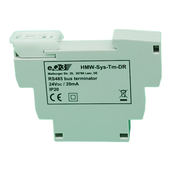
- Seite 8 HMW-Sys-Tm-DR Der Busabschlusswiderstand zur Hutschienenmontage zeigt zusätzlich das Vorhandensein der Betriebs- spannung für das HMW-System und die Übertragung von Daten auf dem Bus mit Leuchtdioden an. Die Montage des Moduls erfolgt auf einer Standard- Hutschiene innerhalb von Haus- und Unterverteilungen.
-
Seite 9: Allgemeine Systeminformation Zu Homematic
Allgemeine Systeminformation zu HomeMatic Dieses Gerät ist Teil des HomeMatic Haussteuersystems. Weitere Anschlusshilfen entnehmen Sie bitte dem HomeMatic Systemhandbuch. Alle technischen Dokumente und Updates finden Sie stets aktuell unter www.HomeMatic.com. Installation Voraussetzung für den Betrieb des Moduls ist eine stabilisierte 24-V- Gleichspannungsversorgung. - Seite 10 HM-Sys-TM: Schalten Sie die Busspannungsversorgung ab. Schließen Sie den Abschlusswiderstand an die Busklemmen und den Spannungsversorgungsanschluss eines beliebigen Moduls am Bus entsprechend nachfolgender Anschlusstabelle an. Ader Klemme Schwarz + 24 V Grün Gelb Lassen Sie keine offenen Leitungsenden am Anschluss liegen! HM-Sys-TM-DR: Schalten Sie die Busspannungsversorgung ab.
-
Seite 11: Wartung Und Reinigung
Zugelassene Leitungsquerschnitte. starre Leitung [mm flexible Leitung mit Aderendhülse [mm 0,14 – 2,50 0,14 – 1,5 Setzen Sie das Modul auf die Hutschiene auf und verriegeln Sie es mit der Schiene. Achten Sie dabei darauf, dass die Rastfeder komplett einrastet und das Gerät fest auf der Schiene sitzt. -
Seite 12: Technische Daten
Technische Daten HMW-Sys-Tm Betriebsspannung: 24 V DC Stromaufnahme: ca. 1 mA Abm. (B x H x T): ca. 14 x 22 x 5 mm HMW-Sys-Tm-DR Betriebsspannung: 24 V DC Stromaufnahme: max. 30 mA Gehäuseabmessungen: Standard- Hutschienengehäuse mit 1 TE Breite... - Seite 14 Function......16 General system information on HomeMatic 19 Installation ......19 Maintenance and cleaning .
-
Seite 15: Information Concerning These Instructions
Information concerning these instructions Read these instructions carefully before beginning operation with your HomeMatic components. Keep the instructions handy for later consultation! Please hand-over the operating manual as well when you hand-over the device to other persons for use. Symbols used: Attention! This indicates a hazard. -
Seite 16: Function
Make sure that the specified wiring and wire cross- sections are used when connecting to device terminals. Function When operating HomeMatic components that must be wired, a termination resistor is required to keep the bus at the proper level and therefore guarantee secure communication. - Seite 17 HMW-Sys-Tm Installing the module can be done anywhere on the bus. The wire lengths of the HMW-Sys-Tm are optimized for connecting to one of the RS485 DIN rail modules. A – Bus connection A B – Bus connection B +/- - Power supply 24 V...
- Seite 18 HMW-Sys-Tm-DR The bus termination resistor for mounting on DIN rails also indicates the existence of the operational power for the HMW system and the transmission of data on the bus with LEDs. The installation of the module is done on a standard DIN rail within the main and sub-divisions.It occupies...
-
Seite 19: General System Information On Homematic
General system information on HomeMatic This device is a component of the HomeMatic Home Control System. Further information on connections are provided in the HomeMatic System Manual. All current technical documents and updates are provided under www.HomeMatic.com. Installation The prerequisite for operating the module is a stabilized 24 V d.c. - Seite 20 HM-Sys-TM: Switch the power supply to the bus off. Connect the termination resistor to the bus terminals and the power supply connection of any module on the bus according to the following connection table. Wire Terminal Black + 24 V Green Yellow Do not leave any open wire ends around the...
-
Seite 21: Maintenance And Cleaning
Permitted wire cross-sections. Rigid wire [mm Flexible wire with end sleeve [mm 0.14 – 2.50 0.14 – 1.5 Position the module on the DIN rail and lock it in place. Make sure that the spring latch is completely latched and that the device is seated solidly on the rail. -
Seite 22: Technical Specifications
HMW-Sys-Tm Operating voltage: 24 V DC Current consumption: approx. 1 mA Dim. (W x H x D): approx. 14 x 22 x 5 mm HMW-Sys-Tm-DR Operating voltage: 24 V DC Current consumption: max. 30 mA Housing dimensions: Standard DIN rail... - Seite 24 eQ-3 AG Maiburger Straße 29 D-26789 Leer www.eQ-3.com...