On Automation EC2AE Anweisungshandbuch
Inhaltsverzeichnis
Verfügbare Sprachen
Verfügbare Sprachen
ANWEISUNGSHANDBUCH / INSTRUCTION MANUAL
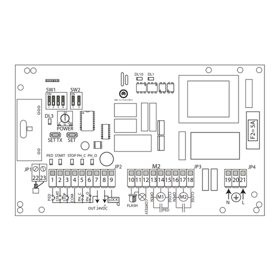
STEUERGERÄT FÜR FLÜGELTORE MIT ANSCHLAG MIT 230 VAC
230VAC CONTROL UNIT FOR SWING GATES
SW1
ON
1 2 3 4
DL3
SET TX SET
PED
JP1
22 23
1 2 3 4
ZWECK DES HANDBUCHES: Dieses Handbuch wurde vom Hersteller erstellt und es ist ein integraler Bestanteil des
Produkts. In ihm sind Informationen erhalten, die erforderlich sind für:
• die korrekte Sensibilisierung der Monteure hinsichtlich der Sicherheitsprobleme;
• die korrekte Installation der Vorrichtung;
• die gründliche Kenntnis ihrer Funktionsweise und ihrer Grenzen;
• die korrekte und sichere Benutzung;
Die konstante Einhaltung der im vorliegenden Handbuch enthaltenen Anweisungen garantiert die Sicherheit des
Menschen, die Wirtschaftlichkeit des Betriebs sowie eine längere Betriebsdauer des Produkts. Zur Vermeidung von
falschen Manövern mit dem Risiko von Unfällen ist es wichtig, dass das vorliegende Handbuch gelesen wird und dass
alle darin enthaltenen Anweisung genau befolgt werden. Die Anweisungen, die Zeichnungen, Die Fotografien und die
Dokumentation, die im vorliegenden Handbuch enthalten sind, sind Eigentum von ON AUTOMATION s.r.l. und sie
dürfen auf keine Weise vervielfältigt werden, weder vollständig, noch auszugsweise.
SCOPE OF THE MANUAL
the necessary information on:
• the safety issues to be drawn to the attention of the installation technicians;
• correct installation of the device;
• operation and the limitations of the device, in detail;
• correct use in conditions of safety;
the instructions in this manual should be observed at all times in order to guarantee personal safety and the cost-effective operation and
long life-span of the product. It is important to have read and understood all the information provided in this manual on how to ensure
correct use and avoid the risk of accidents. The instructions, drawings, photographs and documentation in this manual are the property
of On Automation and must not be reproduced in any way, either in full or in part.
ISCU2AE
ver. 1.0 2018-01-18
EC2AE
SW2
ON
1
2
50
0
100
%
POWER
START STOP PH_C PH_O
JP2
5
6 7
8 9
10
LOCK
-
+
FLASH
OUT 24VDC
this manual was prepared by the manufacturer and forms an integral part of the product. It provides all
:
DL10
DL1
M2
JP3
11 12 13 1415 16 17 18
M1
M2
PED
JP4
19 2021
N
L
Inhaltsverzeichnis

Inhaltszusammenfassung für On Automation EC2AE
- Seite 1 It is important to have read and understood all the information provided in this manual on how to ensure correct use and avoid the risk of accidents. The instructions, drawings, photographs and documentation in this manual are the property of On Automation and must not be reproduced in any way, either in full or in part. ISCU2AE...
- Seite 2 ANWEISUNGSHAND - INSTRUCTION MANUAL Legende der im Handbuch vorhandenen Symbole Dieses Symbol weist auf Teile des Handbuches hin, die aufmerksam gelesen werden müssen Dieses Symbol weist auf Teile des Handbuches hin, die die Sicherheit betreffen Dieses Symbol weist darauf hin, mit Vorsicht vorzugehen Dieses Symbol weist auf den Teil des Handbuches hin, der sich auf die elektrische Verkabelung bezieht Dieses Symbol weist auf den Teil des Anweisungshandbuches hin, der die Programmierung der Zeit der Öffnung und Schließung des Tors betrifft...
-
Seite 3: Grenzen Der Benutzung
21- Abmessungen und Befestigung des Behälters 22- Konformitätserklärung GRENZEN DER BENUTZUNG: Das Gerät EC2AE wurde für die Kontrolle des Betriebs von elektromechanischen oder hydrau- lischen Trieben mit 230 Vac für die Automatisierung von Toren mit einzelnem oder doppeltem angeschlagenem Torflügel entwi- ckelt. -
Seite 4: Technische Daten
ANWEISUNGSHAND - INSTRUCTION MANUAL TECHNISCHE DATEN: Vor der Installation des Produkts sicherstellen, dass die angegebenen Temperaturgrenzwerte für die Installation- sumgebung geeignet sind. BESCHREIBUNG WERT Stromversorgung des Steuergeräts 230 Vac +6 % - 10 % / 50 Hz Stromversorgung Motor 230 Vac +6 % - 10 % max. Leistung 500 W + 500 W Stromversorgung Blinkleuchte 230 Vac für max. -
Seite 5: Elektrischer Schaltplan Der Anlage
ANWEISUNGSHAND - INSTRUCTION MANUAL ELEKTRISCHER SCHALTPLAN DER ANLAGE BESCHREIBUNG DER KABEL FÜR DIE VERKABELUNG NUMMER BESCHREIBUNG KABELTYP Blinkleuchte mit Antenne 2x1 mm² + RG58 (max. empfohlene Länge 5 Meter) Wahlschalter mit Schlüssel 3x1mmq externe Fotozellen TX : 2x1 mm² - RX : 4x1 mm² Getriebemotor 4x1,5 mm²... -
Seite 6: Klem- Beschreibung
ANWEISUNGSHAND - INSTRUCTION MANUAL 7.2- Ausgang für Stromversorgung Zubehör und Elektroschloss: KLEMME BESCHREIBUNG WERT Ausgang für Stromversorgung Zubehör 7= GND -8= 24VDC max. 250 mA Ausgang für Stromversorgung Elektroschloss oder 8= positiv -9= negativ Kontrollleuchte Tor offen, siehe DIP-Switch SWD2- max. -
Seite 7: Zusammenfassendes Schema Der Elektrischen Anschlüsse
ANWEISUNGSHAND - INSTRUCTION MANUAL 8.5- NOTAUS: eine normalerweise geschlossene Taste anschließen oder den Eingang STOP mit COM überbrücken STOP 1 2 3 4 5 6 8.6 Anschluss der Antenne: Der Anschluss muss mit einem koaxialen Kabel RG58 mit einer Länge von nicht mehr als 5 Me- tern vorgenommen werden 22 23 22 23... -
Seite 8: Abkürzung
ANWEISUNGSHAND - INSTRUCTION MANUAL 10- BESCHREIBUNG DER TASTEN AUF DER ABKÜRZUNG BESCHREIBUNG SET TX Taste für die Programmierung und Löschung der Fernbedienungen Taste für die Abspeicherung der Arbeitszeit und der Zeit der automatischen Schließung 11- DESCRIZIONE DEI LED A BORDO SCHEDA ABKÜRZUNG BESCHREIBUNG FARBE... -
Seite 9: Programmierung Des Hubes
ANWEISUNGSHAND - INSTRUCTION MANUAL PROGRAMMIERUNG DES HUBES: 14.1 SCHNELLE PROGRAMMIERUNG FÜR DOPPELTEN ANGESCHLAGENEN TORFLÜGEL: Dieser Typ der Programmierung gestattet die Per- sonalisierung des Verlangsamungsraums des Motors M1 und des Motors M2 sowie der Zeit der Phasenverschiebung der Schließung. Den DIP-Switch SW2-1 in Position OFF bringen, im Programmierungsverfahren entspricht ein Befehl Start dem Drücken der Taste, die dem Eingang START zugeordnet ist (Klemme 1) oder dem Drücken der Taste der Fernbedienung, die als START abgespeichert ist. -
Seite 10: Programmierung Einzelner Angeschlagener Torflügel
ANWEISUNGSHAND - INSTRUCTION MANUAL 14.2 PROGRAMMIERUNG EINZELNER ANGESCHLAGENER TORFLÜGEL: Den DIP-Switch SW2-1 in Position ON bringen. Im Programmierungsverfahren entspricht ein Befehl Start dem drücken der Taste, die mit dem Eingang START verbunden ist (Klemme 1) oder dem Drücken der Taste der Fernbedienung, die als START abgespeichert ist. A - mit Tor in vollständig geschlossener Position die Taste SET drücken, bis die LED DL3 zu blin- ken beginnt B - die Taste SET loslassen X 3 sec. -
Seite 11: Abspeicherung Der Fernsteuerungen
Nach Abschluss der Installation müssen gemäß den Bestimmungen der Maschinenrichtlinie 2006/42 EU muss eine Konformität- serklärung der Maschine, ein programmierter Wartungsplan erstellt und dem Benutzer übergeben werden. PROGRAMMIERTE WARTUNG: Für die elektrische Anlage empfiehlt ON AUTOMATION s.r.l. folgende Wartung Eingriff Intervall Überprüfung des ordnungsgemäßen Betriebs der Vorrichtungen für die Erfassung und die Verhinderung von... -
Seite 12: Probleme Und Lösungen
ANWEISUNGSHAND - INSTRUCTION MANUAL Eingriff Periodicità Kontrolle im Innern des Stromkastens, der sauber und gegen Insekten und Feuchtigkeit geschützt werden muss. 6 mesi Überprüfung der Effizienz der Batterien der Fernbedienungen und gegebenenfalls austauschen 6 mesi Eliminierung eventueller Hindernisse, die den Strahl der Fotozellen permanent unterbrechen (z. B: Zweige oder 6 mesi Sträucher). -
Seite 13: Abmessungen Der An Der Wand Zu Montierenden Box
Die gelieferten Anweisungen sind ein integraler Bestandteil des Produkts und sie müssen aufmerksam gelesen werden, da sie wichtige Hinweise zur Benutzung und Wartung enthalten. Die Anweisungen müssen für alle zukünftigen Benutzer aufbewahrt werden. Das Gerät EC2AE wurde entwickelt für die Kontrolle des Betriebs der elektromechanischen Betriebe mit 230 Vac für die Automatisierung von Toren mit angeschlagenen Flügeln. - Seite 26 ANWEISUNGSHAND - INSTRUCTION MANUAL OVERALL DIMENSIONS OF THE WALL-MOUNTED BOX 215 mm 115 mm 190 mm WARTUNGSREGISTER - MAINTENANCE REGISTER: DATUM ORDENTLICHE AUSSERORDENTLICHE BESCHREIBUNG DES AUSGEWECHSELTE FIRMA DATE WARTUNG WARTUNG EINGRIFFS BAUTEILE SIGNATURE ORDINARY EXTRAORDINARY WORK DESCRIPTION PARTS REPLACED MAINTENANCE MAINTENANCE...
-
Seite 27: Zusammensetzung Der Anlage - System Composition
ANWEISUNGSHAND - INSTRUCTION MANUAL ZUSAMMENSETZUNG DER ANLAGE - SYSTEM COMPOSITION: CODE BESCHREIBUNG MENGE CODE DESCRIPTION QUANTITY ANMERKUNG UND BAUTEILE DER ANLAGE - NOTES AND SYSTEM PARTS:... -
Seite 28: Eu-Konformitätserklärung
EC2AE - Steuergerät für Automatisierungen von angeschlagenen Torflügeln 230 VAC gemäß den anwendbaren Bestimmungen: 89/336/EU, 93/68/EU CE DECLARATION OF CONFORMITY EC2AE - The 230VAC control equipment for the automation of hinged gates conforms to the following standards: 89/336/EEC, 93/68/EEC Via Antonio Ferrero, 9 - Padova 35133 - Italy Tel: +39 049 8876545 www.onautomation.com...