
Verwandte Anleitungen für Schilling SP100+


Inhaltszusammenfassung für Schilling SP100+
- Seite 1 Gesamt-Bedienungsanleitung Entire Instruction Manual SP100+ Deutsch English k:\bedienungsanltg\signiertechnik\ba-erstellung\sp100+\sp100+_gesamt-bedienungsanleitung_de_gb.doc...
- Seite 2 Für Schäden, die dem Unternehmen durch Missachtung entstehen, behält sich dieses alle Rechte vor. The content of this document is owned by Schilling Marking Systems GmbH. It must not be distributed or duplicated as photocopy, sound recording, video, print or microfilm in any form without the approval of the management.
-
Seite 3: Inhaltsverzeichnis
SP100+ brochure ..........................11 SP100+ Benutzerhandbuch ......................11 SP100+ user‘s manual ........................11 1 / 11 Schilling Marking Systems GmbH www.schilling-marking.de ++49 (0)7461 9472-0 ++49 (0)7461 9472-20 Föhrenstr. 47 DE - 78532 Tuttlingen info@schilling-marking.de... -
Seite 4: Anleitung Zum Einlegen Des Klischeebandes
Boden des SP100+, unter der weißen Rolle und zwischen den beiden grünen Abstandshaltern nach Vorne. Bitte die Abstandshalter auf die Breite der Folie einstellen. 1 / 11 Schilling Marking Systems GmbH www.schilling-marking.de ++49 (0)7461 9472-0 ++49 (0)7461 9472-20 Föhrenstr. 47 DE - 78532 Tuttlingen info@schilling-marking.de... - Seite 5 Jetzt schließen Sie den Drucker vorsichtig mit beiden Händen. Mit einem leisen Klick rastet er ein. Jetzt können Sie einfach ihre Schablonen drucken. 2 / 11 Schilling Marking Systems GmbH www.schilling-marking.de ++49 (0)7461 9472-0 ++49 (0)7461 9472-20 Föhrenstr. 47 DE - 78532 Tuttlingen...
-
Seite 6: How To Insert The Stamp Tape Roll Correctly
Please adjust the braces in accordance to the width of the tape. 3 / 11 Schilling Marking Systems GmbH www.schilling-marking.de ++49 (0)7461 9472-0 ++49 (0)7461 9472-20 Föhrenstr. 47 DE - 78532 Tuttlingen... - Seite 7 Close the printer carefully with both hands. Now you can easily print your stencils. 4 / 11 Schilling Marking Systems GmbH www.schilling-marking.de ++49 (0)7461 9472-0 ++49 (0)7461 9472-20 Föhrenstr. 47 DE - 78532 Tuttlingen...
-
Seite 8: Anleitung Für Die Installation Der Bartender Software
If you do not have installation rights on your PC, you will have to have the installation of this software done by your administrator. Follow the instruction on the pictures for installation. 5 / 11 Schilling Marking Systems GmbH www.schilling-marking.de ++49 (0)7461 9472-0 ++49 (0)7461 9472-20 Föhrenstr. - Seite 9 Gesamt-Bedienungsanleitung SP100+ Entire Instruction Manual SP100+ Starten der Software: Starting the Software: 6 / 11 Schilling Marking Systems GmbH www.schilling-marking.de ++49 (0)7461 9472-0 ++49 (0)7461 9472-20 Föhrenstr. 47 DE - 78532 Tuttlingen info@schilling-marking.de...
- Seite 10 Gesamt-Bedienungsanleitung SP100+ Entire Instruction Manual SP100+ Änderung der Sprache: Change the language: 7 / 11 Schilling Marking Systems GmbH www.schilling-marking.de ++49 (0)7461 9472-0 ++49 (0)7461 9472-20 Föhrenstr. 47 DE - 78532 Tuttlingen info@schilling-marking.de...
-
Seite 11: Anleitung Für Die Installation Des Windows 7 Druckertreiber
Follow the instruction on the pictures for installation. (Von der CD / From the 8 / 11 Schilling Marking Systems GmbH www.schilling-marking.de ++49 (0)7461 9472-0 ++49 (0)7461 9472-20 Föhrenstr. 47 DE - 78532 Tuttlingen info@schilling-marking.de... - Seite 12 Open the printer driver in you windows system (printer settings): Änderung der Papiergröße: Änderung der gesamten Etiketteneinstellung: Change the paper dimensions: Change all the tape formats: 9 / 11 Schilling Marking Systems GmbH www.schilling-marking.de ++49 (0)7461 9472-0 ++49 (0)7461 9472-20 Föhrenstr. 47 DE - 78532 Tuttlingen info@schilling-marking.de...
-
Seite 13: Anleitung Für Die Papierrückzugunterdrückung
Instructions on how to avoid the stamp tape from reverse-feeding Einstellungen in der BarTender-Software unter „Datei“ -> Druckeinstellungen Open BarTender Software and go to “File” -> Printer Settings 10 / 11 Schilling Marking Systems GmbH www.schilling-marking.de ++49 (0)7461 9472-0 ++49 (0)7461 9472-20 Föhrenstr. 47 DE - 78532 Tuttlingen... -
Seite 14: Anlagen
Confirm all windows with OK. Anlagen / Appendices - SP100+ Prospekt - SP100+ brochure - SP100+ Benutzerhandbuch - SP100+ user‘s manual 11 / 11 Schilling Marking Systems GmbH www.schilling-marking.de ++49 (0)7461 9472-0 ++49 (0)7461 9472-20 Föhrenstr. 47 DE - 78532 Tuttlingen info@schilling-marking.de... - Seite 15 - Create jobs directly with Windows or optional by print programme - Use all fonts available on PC - Universal operation possibilities - Quick, easy and individual production of stencils Only by Schilling Marking Systems! P.t.o. for the printer Technical modifications reserved K:\Prospekte\Signiertechnik\Prospekt-Erstellung\SP-100 without prices_GB.cdr Edition: 02/12 Schilling Marking Systems GmbH www.schilling-marking.de...
- Seite 16 - Interfaces: Parallel/RS232 22.4110.06 110mm x 300m Blue 22.4110.09 110mm x 300m White Technical modifications reserved K:\Prospekte\Signiertechnik\Prospekt-Erstellung\SP-100 without prices_GB.cdr Edition: 02/12 Schilling Marking Systems GmbH www.schilling-marking.de +49 (0)7461 9472-0 +49 (0)7461 9472-20 In Grubenäcker 1 DE - 78532 Tuttlingen info@schilling-marking.de...
- Seite 17 TTP-245 Series/343 Series THERMAL TRANSFER / DIRECT THERMAL BAR CODE PRINTER USER’S MANUAL...
- Seite 18 Contents ................1 OPYRIGHT ECLARATION ....................1 OMPLIANCES 1. Introduction ...................1 2. Getting Started..................1 2.1 Unpacking and Inspection ...............1 2.2 Equipment Checklist ...............1 2.3 Printer Parts ..................3 3. Setup ....................4 3.1 Setting Up the Printer ..............4 3.2 Loading the Ribbon .................4 3.3 Loading Label Stock................6 3.4 External Label Roll Mount Installation (Option) .......8 3.5 Peel-off Module Installation (Option) ..........10 3.5.1 Loading the Paper in Peel-off Mode ........13...
-
Seite 19: Opyright Declaration
Copyright Declaration Information in this subject to change without notice and does not represent a commitment on the part of TSC Auto ID Technology Co., Ltd.. No part of this manual may be reproduced or transmitted in any form by any means, for any purpose other than the purchaser’s personal use, without the expressed written permission of TSC Auto ID Technology Co., Ltd.. - Seite 20 8. Dieses das Gerät kann bis zu einer Außentemperatur von maximal 40℃ betieben werden.
-
Seite 21: Introduction
1. Introduction Thank you for purchasing the TSC TTP-245 series/343 series Thermal Transfer and Direct Thermal Bar Code Printers. Although the printer takes only a small amount of space, it delivers reliable, superior performance. This printer provides both thermal transfer and direct thermal printing at user selectable speed of: 2.0, 3.0, 4.0 or 5.0 ips, for TTP-245 series;... - Seite 22 If any parts are missing, please contact the Customer Service Department of your purchased reseller or distributor. Options External label roll mount Label spindle (3-inch diameter core) Programmable keyboard (KU-007 Plus) Stand-alone LCD keyboard (KP-200) Automatic cutter module Peel off module Internal Ethernet print server External 802.11b/g wireless print server...
-
Seite 23: Printer Parts
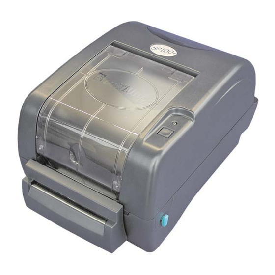
2.3 Printer Parts Clear Window Ribbon Access Cover LED Indicator Feed Button Printer Top Cover Top Cover Open Lever Fig. 1 Top front view 1. USB Interface 2. Centronics Interface 3. RS-232C DB-9 Interface 4. Power Jack 5. Power Switch 6. -
Seite 24: Setup
3. Setup 3.1 Setting Up the Printer 1. Place the printer on a flat, secure surface. 2. Make sure the power switch is off. 3. Connect the printer to the computer with the Centronics or USB cable. 4. Plug the power cord into the power supply connector at the rear of the printer, and then plug the power cord into a properly grounded receptacle. - Seite 25 Make sure the printer top cover is engaged properly at both sides prior to powering up the printer. Please follow the steps below to install the ribbon into printer. 1. Push down on the ribbon access window to unlatch and open the cover. 2.
-
Seite 26: Loading Label Stock
Ribbon supply spindle Ribbon Lead Tape Rear Hub Ribbon Rewind Spindle with Paper Core Fig. 5 Ribbon installation (II) 3.3 Loading Label Stock 1. Insert a 1” label spindle into a paper roll ( * f your paper core is 1 inch, remove the 1.5”... - Seite 27 located on each side of the printer and lifting the top cover. A top cover support at the rear of the printer will hold the printer top cover open. Lower Cover Fig. 7 Pull the lever to open the cover 3.
-
Seite 28: External Label Roll Mount Installation (Option)
Printer Top Cover Top Cover Support Paper Roll Mount Teflon Bar Paper Guide Top Cover Open Lever Fig. 8 Label installation (II) 3.4 External Label Roll Mount Installation (Option) 1. Attach an external paper roll mount on the bottom of the printer. Fig. - Seite 29 External Paper Roll Mount External Paper Feed Opening Fig. 10 External roll mount label installation (I) 4. Feed the paper, printing side face up, through the paper guide and pass over the platen. 5. Adjust the paper guides to fit the paper width. 6.
-
Seite 30: Peel-Off Module Installation (Option)
3.5 Peel-off Module Installation (Option) 1. Open the top cover and remove the front panel from the printer. Front Panel Fig. 12 Remove the front panel 2. Open the top cover and hold it and push down and push backward the top cover support then push backward the top cover. - Seite 31 screw at memory card cover. 5. Hold the lower cover to lift up the top cover open levers to separate the lower inner cover and the lower cover. 6. Arrange the cable through the bezel. Connect the peel-off panel cable to the 5-pin socket on printer PCB.
- Seite 32 7. Insert the peel-off tenons into the lower inner cover mortises until tenons snap into places. Lower Inner Cover Roller Lower Cover Tenon Mortise Fig. 16 Peel-off panel installation (I) 8. Arrange the lower inner cover back to the lower cover. Peel-off panel Roller...
-
Seite 33: Loading The Paper In Peel-Off Mode
3.5.1 Loading the Paper in Peel-off Mode Note: Both thermal paper and plain paper apply for peel-off function but neither PVC nor vynle work at peel-off function. 1. Insert a 1” label spindle into a paper roll. 2. Open the printer top cover by pulling the top cover open levers. The top cover support will hold the printer top cover. - Seite 34 Fig. 19 Open the peel-off panel 5. Feed the paper, printing side facing up, through the paper guide and pass over the platen. 6. Lead the paper through the backing paper opening, beneath the roller, and tear off one piece of the label. 7.
-
Seite 35: Cutter Module Installation (Option)
Fig. 21 Complete label installation for peel-off mode 3.6 Cutter Module Installation (Option) 1. Pull the top cover open levers to open the top cover. 2. Remove the front panel from the lower cover. Lower Cover Fig. 22 Pull the lever to open the cover 3. - Seite 36 Fig. 23 Remove 6 screws from lower inner cover 5. Place the printer upside down and unscrew the two screws of the hinge holder on the lower cover. Unscrew the screw of the memory card cover. 6. Use both thumbs to hold the lower cover and index fingers to lift up the top cover open levers to separate the lower inner cover and the lower cover.
-
Seite 37: Loading Label In Cutter Mode
Fig. 25 Cutter module cable arrangement 8. Arrange the lower inner cover back to the lower cover. 9. Install the cutter into the niches of the printer. Cutter Niche Fig. 26 Cutter module installation 10. Use a screwdriver to screw whole screws on the lower inner cover and the lower cover. -
Seite 38: Instructions To Top Cover Operation
Top Cover Top Cover Support Paper Guide Platen Cutter Fig. 27 Label installation in cutter mode 7. Close the top cover by lifting up the top cover support and close the cover slowly. Fig. 28 Complete label installation in cutter mode 3.7 Instructions to Top Cover Operation Please take care when opening or closing the printer’s top cover by carefully following these instructions. - Seite 39 2. Lift up the top gradually. There are two stop positions for the top cover. Position 1 and 2 are indicated on the label below. Note: To hold the cover open at position 1, you must lift the cover higher than the stopping point at position 1 and gently lower the cover to stop position 1.
- Seite 40 Fig. 2 Top cover is fully open and ready to close Fig. 3 Use both hands to close the top cover 5. Do not force the cover! If you are not sure if top cover is fixed at stop position, please do not push top cover to close it or the top cover will be damaged.
-
Seite 41: Power On Utilities
4. Power on Utilities There are six power-on utilities to set up and test printer hardware. These utilities are activated by pressing FEED button and by turning on the printer power simultaneously. The utilities are listed as below: Ribbon sensor calibration and Gap or black mark sensor calibration Gap/black mark sensor calibration;Self-test and dump mode Printer initialization Set black mark sensor as media sensor and calibrate the black mark... -
Seite 43: Gap/Black Mark Calibration, Self-Test And Dump Mode
4.2 Gap/Black Mark Calibration, Self-test and Dump Mode While calibrate the gap/black mark sensor, printer will measure the label length, print the internal configuration (self-test) on label and then enter the dump mode. To calibrate gap or black mark sensor, depends on the sensor setting in the last print job. - Seite 44 Self-test Printer will print the printer configuration after gap/black mark sensor calibration. Self-test printout can be used to check if there is any dot damage on the heater element, printer configurations and available memory space. Print head check pattern Firmware version Firmware checksum Printed mileage (meter) Serial port configuration...
- Seite 45 Dump mode Printer will enter dump mode after printing printer configuration. In the dump mode, all characters will be printed in 2 columns as following. The left side characters are received from your system and right side data are the corresponding hexadecimal value of the characters.
-
Seite 46: Printer Initialization
4.3 Printer Initialization Printer initialization is used to clear DRAM and restore printer settings to defaults. The only one exception is ribbon sensitivity, which will note be restored to default. Printer initialization is activated by the following procedures. 1. Turn off the power switch. 2. -
Seite 47: Set Black Mark Sensor As Media Sensor And Calibrate The Black
4.4 Set Black Mark Sensor as Media Sensor and Calibrate the Black Mark Sensor Please follow the steps as below. 1. Turn off the power switch. 2. Hold on the button then turn on the power switch. 3. Release the button when LED turns green/amber after 5 green blinks. (Any green/amber will do during the 5 blinks). - Seite 48 1. Turn off printer power. 2. Press the FEED button and then turn on power. 3. Release the FEED button when LED becomes solid green. The LED color will be changed as following: Amber red (5 blinks) amber (5 blinks) green (5 blinks) green/amber (5 blinks) red/amber (5 blinks)
-
Seite 49: Maintenance
5. Maintenance 5.1 Cleaning Use one or more of the following supplies that meets your needs: Cotton swab Lint-free cloth Vacuum 100% ethanol The cleaning process is described as following Printer Part Method 1. Always turns off the printer before cleaning the Printer Head print head. -
Seite 50: Troubleshooting
6. Troubleshooting This section lists the common problems that according to the LED status and other problems you may encounter when operating the printer. Also, it provides solutions. 6.1 LED Status LED Status / Color Printer Status Solution Number Solid Green Green with blinking Pause Red with blinking... -
Seite 51: Print Quality
6.2 Print Quality Continuous feeding labels The printer setting may go wrong. Please do the Initialization and Gap/Black Mark Calibration. No print on the label Is the label or ribbon loaded correctly? Follow the instructions in Loading the Paper or Loading the Ribbon. Does the ribbon run out? Follow the instructions in Loading the Ribbon. -
Seite 52: Led And Button Operation
7. LED and Button Operation 7.1 LED LED Color Description Green/ Solid This illuminates that the power is on and the device is ready to use. Green/ Flash This illuminates that the system is downloading data from PC to memory and the printer is paused. Amber This illuminates that the system is clearing data from printer. - Seite 53 1. Turn off the power switch. Ribbon Sensor and 2. Hold on the button then turn on the power switch. Gap/Black Mark 3 Release the button when LED becomes red and blinking. Sensor Calibration (Any red will do during the 5 blinks). It will calibrate the ribbon sensor and gap/black mark sensor sensitivity.
- Seite 54 1. Turn off the power switch. Printer 2. Hold on the button then turn on the power switch. Initialization 3. Release the button when LED turns green after 5 amber blinks. (Any green will do during the 5 blinks). The LED color will be changed as following: Amber red (5 blinks) amber (5 blinks)
- Seite 55 1. Turn off printer power. Skip AUTO.BAS 2. Press the FEED button and then turn on power. 3. Release the FEED button when LED becomes solid green. The LED color will be changed as following: Amber red (5 blinks) amber (5 blinks) green (5 blinks) green/amber (5 blinks)
- Seite 56 Headquarters / Factory Taipei Office No. 35, Sec. 2, Ligong 1st Rd., Wujie Town 11F, No. 205, Sec. 3, Beishin Rd., Shindian City, , I-Lan County, Taiwan 268, R.O.C. Taipei 231, Taiwan, R.O.C.Taiwan 268, R.O.C. TEL: +886-3-990-6677 TEL: +886-2-8913-1308 FAX: +886-3-990-5577 FAX: +886-2-8913-1808 Web site: www.tscprinters.com E-mail: printer_sales@tscprinters.com...