Inhaltsverzeichnis
Werbung
Verfügbare Sprachen
Verfügbare Sprachen
E Schaudt GmbH, Elektrotechnik und Apparatebau, Planckstraße 8, 88677 Markdorf, Germany, Tel. +497544 9577-0,Fax +49 7544 9577-29,www.schaudt--gmbh.de
9310330 MA /EN
Installation Instructions
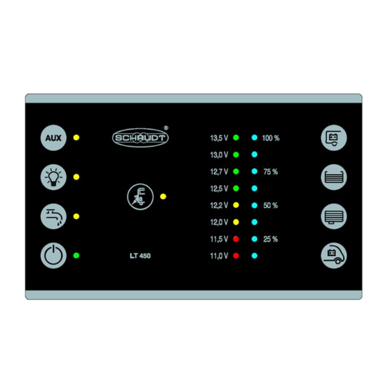
Operator and control panel Model LT 45X
AIways follow the corresponding operating instruction manual.
Table of contents
1
S a f e t y i n f o r m a t i o n . . . . . . . . . . . . . . . . . . . . . . . . . . . . . . . . . . . . . .
1.1
Meaningofsafetysymbols...............................
1.2
Generalsafetyinformation...............................
2
I n t r o d u c t i o n . . . . . . . . . . . . . . . . . . . . . . . . . . . . . . . . . . . . . . . . . . . .
3
Mechanical installation ...................................
4
Electrical connection ....................................
4 . 2
S e n s o r s . . . . . . . . . . . . . . . . . . . . . . . . . . . . . . . . . . . . . . . . . . . . . . .
4.3
ElectroblockEBL ... /caravan powersupplyCSV ... . . . . . ....
5
I n i t i a l u s e . . . . . . . . . . . . . . . . . . . . . . . . . . . . . . . . . . . . . . . . . . . . . .
5.1
Checkspriortoinitialuse ................................
5.2
5 . 3
S h u t t i n g d o w n . . . . . . . . . . . . . . . . . . . . . . . . . . . . . . . . . . . . . . . . . .
6
Storage,packagingandtransportation.....................
2
2
2
3
3
4
5
5
5
5
5
6
6
Date: 12.07.2018
Werbung
Kapitel
Inhaltsverzeichnis

Verwandte Anleitungen für Schaudt LT 45X Series

Inhaltszusammenfassung für Schaudt LT 45X Series
-
Seite 1: Inhaltsverzeichnis
S h u t t i n g d o w n ......... . Storage,packagingandtransportation..... E Schaudt GmbH, Elektrotechnik und Apparatebau, Planckstraße 8, 88677 Markdorf, Germany, Tel. +497544 9577-0,Fax +49 7544 9577-29,www.schaudt--gmbh.de 9310330 MA /EN... -
Seite 2: Safety Information
Installation Instructions Operator and control panel LT 45X Safety information Meaning of safety symbols DANGER! Failure to comply with this sign may result in danger to life or physical con- dition. WARNING! Failure to comply with this sign may result in injury. ATTENTION! Failure to comply with the sign may result in damage to equipment or other connected consumers. -
Seite 3: Introduction
Installation Instructions Operator and control panel LT 45X Introduction These installation instructions are aimed at trained personnel. They contain important informationon the connection and safe operation of the device. The safety informationprovided must be observed. Mechanical installation Plug connectors Attachment clip (180) 4.5* 171*... -
Seite 4: Electrical Connection
Installation Instructions Operator and control panel LT 45X Environment Install in a dry, sufficiently ventilated location. " The ambient temperature may not exceed +50 Cduring operation. Minimum clearance Maintain a minimumclearance to the surrounding fixtures and fittings: " The installation depth is 10 mm, near the 3 plug connectors 30 mm Fitting Attach the LT 45X control panel: Make a furniturecutout as in Fig. -
Seite 5: Sensors
Installation Instructions Operator and control panel LT 45X Sensors Connect the tank sensors for two different tanks: " 5-pinconnector: Waste water tank 6-pinconnector: Water tank EBL... electroblock /CSV... caravan power supply Plug the ready-made cable (13-pin)into the LT 45X control panel. "... -
Seite 6: Storage,Packagingandtransportation
Installation Instructions Operator and control panel LT 45X Touch the sensor for the main 12V ON/OFF switch " The green indicator LED lights up. The 12V leisure area supply is switched on. Effecting a shutdown ATTENTION! Once the production of the vehicle is complete, the system MUST be shut down. -
Seite 7: Bedien-Und Kontrollpanel Serie Lt 45X
E r s t i n b e t r i e b n a h m e ........PrüfungenvorErstinbetriebnahme ......Ein-und Ausschaltender 12 V VersorgungWohnraum..Stilllegungherbeiführen........Lagerung-Verpackung-Transport......E Schaudt GmbH, Elektrotechnik und Apparatebau, Planckstraße 8, 88677 Markdorf, Germany, Tel. +497544 9577-0,Fax +49 7544 9577-29,www.schaudt--gmbh.de 9310330 MA /DE Datum: 12.07.2018... -
Seite 8: Sicherheitshinweise
Montageanleitung Bedien-und Kontrollpanel LT 45X Sicherheitshinweise Bedeutung der Sicherheitshinweise GEFAHR! Die Nichtbeachtung dieses Zeichens kann zur Gefährdung von Leib und Leben führen. WARNUNG! Die Nichtbeachtung dieses Zeichens kann zu Verletzungen von Personen führen. ACHTUNG! Die Nichtbeachtungdieses Zeichens kann zu Schäden am Gerät oder an angeschlossenen Verbrauchern führen. -
Seite 9: Einleitung
Montageanleitung Bedien-und Kontrollpanel LT 45X Einleitung Diese Montageanleitung wendet sich an ausgebildetes Fachpersonal. Sie enthält wichtige Hinweise zum Anschließen und zum sicheren Betrieb des Gerätes. Die angegebenen Sicherheitshinweise sind unbedingtanzu- wenden. Mechanischer Einbau Steckverbinder Befestigungs--Clip (180) 4.5* 171* 10 (4x)* 30** 120** Eckenaus... -
Seite 10: Elektrischer Anschluss
Montageanleitung Bedien-und Kontrollpanel LT 45X Umgebung Trockenen und ausreichend belüfteten Einbauort wählen. " Während des Betriebs darf die Umgebungstemperatur +50 Cnicht überschreiten. Mindestabstand Mindestabstände zu den umgebenden Einrichtungsgegenständen sicher- " stellen: Die Einbautiefe beträgt 10 mm, im Bereich der 3 Steckverbinder 30 mm Befestigung Bedien-und Kontrollpanel LT 45X befestigen:... -
Seite 11: Sensoren
Montageanleitung Bedien-und Kontrollpanel LT 45X Sensoren Tanksensoren für zwei verschiedene Tanks anschließen: " Stecker 5 polig:Abwassertank Stecker 6 polig:Wassertank Elektroblock EBL ... bzw. Caravan-StromversorgungCSV ... Das vorkonfektionierteKabel (13 polig) an Bedien-und Kontrollpanel " LT 45X einstecken. Das andere Ende des vorkonfektioniertenKabels am Stromversorgungs- "... -
Seite 12: Stilllegungherbeiführen
Montageanleitung Bedien-und Kontrollpanel LT 45X Das Sensor-TastfeldHauptschalter 12 V EIN /AUS berühren. " Die grüne Kontroll-LED leuchtet. Die 12 V Versorgung des Wohnraums ist eingeschaltet. Stilllegung herbeiführen ACHTUNG! Nachdem die Produktion des Fahrzeugs abgeschlossen ist, MUSS das System stillgelegt werden. 12 V Versorgung ausschalten.