System Sensor M210E-CZR Kurzbedienungsanleitung
Verfügbare Sprachen
Verfügbare Sprachen
94 mm
83 mm
1
2
3
4
A B
5
1
6
7
0
8
9
10
8 9
8 9
11
6 7
6 7
10
11
5
5
12
4
4
12
3
3
13
2
2
14
1
1
0
15
0
A
x10
B
x1
C
1:1 M200E-SMB
a
b
-
c
+
-
d
+
e
+
(-)
(-) (+)
g
j
f
i
h
Fig./Abb. 3
D200-95-01
23 mm
93
mm
110 g
M200E-SMB
1:3 M200E-PMB
1:2 M200E-DIN
Fig./Abb. 1
M210E-CZR
8 9
6 7
10
(+)
11
5
4
12
3
13
2
14
1
0
15
A
x10
k
Fig./Abb. 2
M210E-CZR
DOP-IOD032
EN54-17: 2005
EN54-18: 2005
Pittway Tecnologica S.r.l
Via Caboto 19/3
34147 Trieste, Italy
Pittway Tecnologica S.r.l, Via Caboto 19/3, 34147 Trieste, Italy
M210E-CZR
EN
This manual is intended as a quick reference installation guide. Please refer to the
control panel manufacturers installation manual for detailed system information.
60°C
The M200 series of modules are a family of microprocessor controlled interface
devices permitting the monitoring and/or control of auxiliary devices.The M210E-CZR
is used to link a zone of conventional devices to an intelligent system controlled by
-20°C
an addressable panel. The CZR has a resistor built in, making it especially suitable
for connection to a conventional zone that operates in a hazardous area requiring
intrinsically safe equipment.
The module must only be connected to control panels using compatible proprietary
addressable communication protocols for monitoring and control. The module is
compatible with System Sensor intrinsically safe sensors mounted in the B401 base,
for use with these barriers:
MTL models 4561 and 5561.
145 g
Pepperl + Fuchs models KFDO-CS-Ex1.51P and KFDO-CS-Ex2.51P.
NOTE: When an intrinsically safe system is used on the loop, a short on the sensor
side of the barrier will result in an alarm. Only a short on the module side of the safety
barrier will generate a fault signal.
A single tri-colour LED indicates the status of the module. In normal conditions, the
LED can be set by command from the control panel to blink green when the module
is polled. In the case of a fire alarm on the conventional zone, the LED is switched
on constant red by panel command. If a fault is detected on the conventional zone or
the zone supply voltage drops below 12V, or a fault with the external power supply is
signalled, the LED will blink yellow if enabled on the control panel. When a short circuit
is detected on the loop to either side of the module, the LED is switched to show a
constant yellow light.
SPECIFICATIONS
Intelligent Loop
Operating Voltage Range with Isolator: 15 to 28VDC (Min 17.5VDC for LED operation)
Op. Volt. Range (Isolator Disabled): 15 to 30VDC (Min 17.5VDC for LED operation)
Max. Standby Current (µA @24 V and 25
No Communication:
Communication LED blink enabled - 5 secs:
Read 16 sec. LED blink 8 sec:
Max. Standby Current (mA @24 V and 25
resistive EOL only (no detectors), Loop Powered Conventional Zone:
No Communication:
Communication LED blink enabled - 5 secs:
Read 16 sec. LED blink 8 sec:
LED Current (Red):
8 9
6 7
5
LED Current (Yellow):
4
3
2
Maximum rated continuous current with the
1
0
B
x1
C
Maximum rated isolator switching current (under short circuit) (I
Maximum leakage current (I
Maximum series impedance with the isolator closed (Z
Conventional Zone
External Supply Voltage:
Maximum Standby Load Current: 2.8 mA for detectors at 18 VDC
Maximum Zone Load:
Maximum Conventional Line Resistance: 50 Ohms
End of Line Resistor:
General
Humidity:
Ingress protection:
Maximum Wire Gauge:
INSTALLATION
M200 series modules can be mounted in several ways (See Figure 1):
1:1 An M200E-SMB custom low profile surface-mounting box. The SMB Base is
affixed to mounting surface, and then the module and cover are screwed onto
the base using the two screws supplied. Box dimensions: 132mm(H) x 137mm(W)
x 40mm(D)
1:2 An M200E-DIN Adaptor allows mounting onto standard 35mm x 7.5mm "Top Hat"
DIN rail inside a control panel or other suitable enclosure. Push module into adaptor
bracket until it clips into place. Locate top clip over DIN rail and rotate bottom down
0832
to clip into place. To remove, lift up, then rotate top away from the rail.
10
1:3 An M200E-PMB Panel Mount Bracket allows the module to be mounted directly
into a panel or other suitable enclosure. Adaptor bracket is mounted directly into
panel using 2 x M4 Pan head screws. Module is pushed into adaptor until it clips
into place.
Wiring to all series M200 modules is via plug in type terminals capable of supporting
conductors up to 2.5mm²
Disconnect loop power before installing modules or sensors.
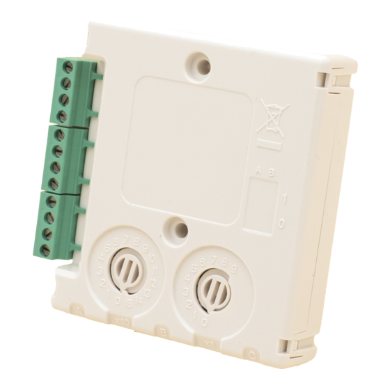
The module address is selected by means of rotary decade address switches (see
Figure 3). A screwdriver should be used to rotate the wheels to select the desired
address, either from the front or the top of the module.
INSTALLATION INSTRUCTIONS - M210E-CZR
CONVENTIONAL ZONE INTERFACE MODULE
18 to 32VDC if conventional zone is loop powered
C) External Supply Conventional Zone:
o
C) Conventional Zone connected to
o
2.2mA
8.8mA
isolator
max) with the isolator open (isolated state): 15mA
L
12 to 28.5 VDC
18 to 28.5 VDC if conventional zone is loop powered
3.8 mA for detectors at 24 VDC
60mA (Limited internally)
3.9 K Ohms, 5% (Supplied)
5% to 95% relative humidity (non-condensing)
IP50 (Mounted in M200E-SMB)
2.5mm²
CAUTION
I 56- 3572- 020
288
500
388
6.5
6.7
6.6
closed (I
max): 1A
c
max): 1A
s
max): 170 m ohm at 15Vdc
c
I56-3572-020

Verwandte Anleitungen für System Sensor M210E-CZR

Inhaltszusammenfassung für System Sensor M210E-CZR
- Seite 4 Barriere eine Alarmmeldung. Nur ein Kurzschluss auf der Modulseite der M210E-CZR Anschaltung Sicherheitsbarriere wird als Störung angezeigt. Das Modul M210E-CZR kann so angeschaltet werden, dass die Standardmeldergruppe Der Modulstatus wird mit einer 3-farbigen LED angezeigt. Im Normalbetrieb kann von einem externen Netzteil oder, vorausgesetzt der Strombedarf kann gedeckt die LED durch ein Kommando der BMZ grün blinkend angesteuert werden, wenn...