Inhaltsverzeichnis
Werbung
Verfügbare Sprachen
Verfügbare Sprachen
Quicklinks
Werbung
Kapitel
Inhaltsverzeichnis
Fehlerbehebung

Verwandte Anleitungen für Videotec Ulisse Compact Thermal

Inhaltszusammenfassung für Videotec Ulisse Compact Thermal
- Seite 1 ULISSE COMPACT THERMAL Outdoor PTZ camera Dual Vision, Day/Night and Thermal, for total darkness monitoring English - Instructions manual Italiano - Manuale di istruzioni Français - Manuel d’instructions Deutsch - Bedienungslanleitung Русский - Руководство по эксплуатации...
- Seite 3 ULISSE COMPACT THERMAL Outdoor PTZ camera Dual Vision, Day/Night and Thermal, for total darkness monitoring English - Instructions manual...
-
Seite 5: Inhaltsverzeichnis
Contents ENGLISH 1 About this manual ......................7 1.1 Typographical conventions ..........................7 2 Notes on copyright and information on trademarks ..........7 3 Safety rules........................7 4 Identification ........................ 10 4.1 Product description and type designation....................10 4.2 Product markings ..............................10 4.2.1 Checking the markings ...............................10 5 Preparing the product for use .................. - Seite 6 6.11.4.1 Two-way RS-485 TX/RX line ..................................20 6.11.4.2 Line RS-485-1 reception, line RS-485-2 repetition........................20 6.11.4.3 Two-way RS-422 line ....................................20 6.11.4.4 One-way RS-485 line ....................................20 6.11.5 Serial line terminations ..............................21 6.11.6 Protocol configuration ..............................21 6.11.7 Address configuration ...............................21 7 Switching on ........................ 22 7.1 First start-up................................22 7.2 Checks list .................................22 8 Configuration .......................
- Seite 7 8.1.16 Thermal Camera Menu ..............................42 8.1.16.1 Flat Field Correction Menu ..................................43 8.1.16.2 Flat Field Correction Menu (Gain Switch Values) ..........................44 8.1.16.3 Video Setup Menu ....................................44 8.1.16.4 Gain Control Menu....................................45 8.1.16.5 ROI Setup Menu ......................................46 8.1.16.6 Thermal Analysis Menu ..................................46 8.1.16.7 Thermal Analysis Menu (Spot Meter) ..............................46 8.1.16.8 Thermal Analysis Menu (Isotherm) ..............................47 8.1.16.9 Status Menu .......................................47 9 Accessories ........................
- Seite 8 15.7 Environment................................63 15.8 Certifications .................................63 16 Technical drawings ....................64 A Appendix - Address table ................... 65 MNVCUCT_1511_EN...
-
Seite 9: About This Manual
1 About this manual 3 Safety rules Before installing and using this unit, please read this CAUTION! The electrical system to which manual carefully. Be sure to keep it handy for later the unit is connected must be equipped reference. with a 20A max automatic bipolar circuit breaker. - Seite 10 • The manufacturer declines all responsibility • Installation category (also called Overvoltage for any damage caused by an improper use Category) specifies the level of mains voltage of the appliances mentioned in this manual. surges that the equipment will be subjected to. Furthermore, the manufacturer reserves the right The category depends upon the location of the to modify its contents without any prior notice.
- Seite 11 • Connect the device to a power source • Only skilled personnel should carry out corresponding to the indications given on the maintenance on the device. When carrying out marking label. Before proceeding with installation maintenance, the operator is exposed to the risk of make sure that the power line is properly isolated.
-
Seite 12: Identification
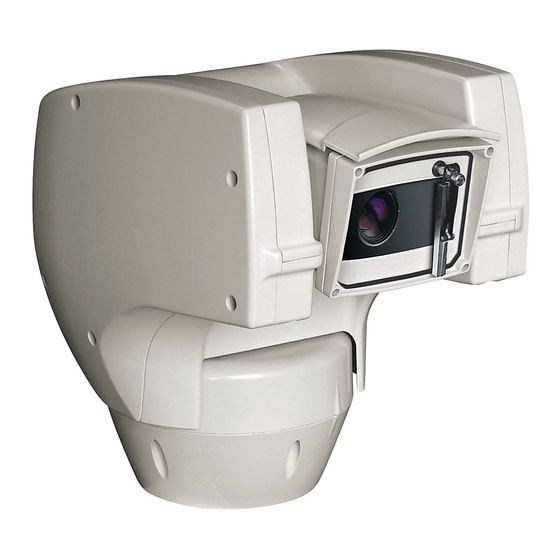
Pan & tilt devices have a label complying with CE markings. designation The PTZ ULISSE COMPACT THERMAL camera offers an exceptional integrated solution, for effective monitoring even in complete darkness or in extreme environmental conditions, fog, rain, smoke, or for long distances. -
Seite 13: Preparing The Product For Use
5 Preparing the product for 5.2 Unpacking When the product is delivered, make sure that the package is intact and that there are no signs that it has been dropped or scratched. Any change that is not expressly approved by the manufacturer will invalidate the If there are obvious signs of damage, contact the guarantee. -
Seite 14: Preparatory Work Before Installation
6 Installation 5.5 Preparatory work before installation Never, under any circumstances, make any changes or connections that are not 5.5.1 Attaching the bracket shown in this handbook. Failure to follow Different types of supports are available (9 the connection instructions that are given Accessories, page 48). -
Seite 15: Fixing The Base To The Support
6.2 Fixing the base to the support 6.3 Connection of the connector board Use the screws and the washers supplied with the base. 6.3.1 Connector board description After having positioned gasket (01), fasten base (02) BOARD DESCRIPTION on support (03) using screws (04), toothed spring Connector Function washers and the flat washers (05). -
Seite 16: Connection Of The Power Supply Line
6.3.2 Connection of the power supply Connect the power supply cables to the J2 terminal as described in the table. line CONNECTION OF THE POWER SUPPLY LINE Electrical connections must be performed Colour Terminals with the power supply disconnected and Power supply 24Vac the circuit-breaker open. -
Seite 17: Connection Of The Secondary Connector Board
6.4 Connection of the secondary 6.4.2 Connection of the alarm inputs connector board In case of free contact alarm make the connection as shown in the figure. All signal cables must be grouped together The alarm contacts are present on connector (CN1- by means of a strap. -
Seite 18: Connections Of One Or More Video Cables
6.5 Connections of one or more 6.5.2 Connecting the secondary video video cables Connect the coaxial cable to the BNC connector (not supplied) and then connect it to connector CN3. CDS installation type (Cable Distribution System). The installation is type TNV-1, do not connect it to SELV circuits. -
Seite 19: Connecting The Direct Control Line Of The Thermal Camera Rs-485-3 (Only For Models With Double Camera)
6.6 Connecting the direct control 6.8 Termination of the RS-485-3 line of the thermal camera RS- serial line (DS1) 485-3 (only for models with Dip-switch 2 enables the termination (120 Ohm) of double camera) the serial line. The thermal camera can be externally controlled by the serial line (CN4, 8.1.16 Thermal Camera Menu, page 42). -
Seite 20: Fixing The Upper Body
6.10 Fixing the upper body 6.11 Hardware configuration Point the self-centering connector (01) of the upper 6.11.1 Opening the configuration door unit. Point the side set (02) so that it faces the frontal Before powering the device it must be configured vision of the camera. -
Seite 21: Setting The Configuration Check Mode (Dip 1)
6.11.2 Setting the configuration check 6.11.4 Setting of the serial mode (DIP 1) communication lines To set the serial communication lines operate on SW 1=ON: Display Configuration. To be used only to verify the configuration at the end of the setting. To DIP 1. -
Seite 22: Two-Way Rs-485 Tx/Rx Line
6.11.4.1 Two-way RS-485 TX/RX line 6.11.4.3 Two-way RS-422 line With this setting it is possible to obtain a bi- This setting allows full duplex communication directional, half/duplex, communication on the according to the RS-422 standard. RS-485-1 line. Line RS-485-1 is always in receiving mode (RS-422- The RS-485-2 serial line is not used. -
Seite 23: Serial Line Terminations
SW 1 SW 2 SW 3 SW 4 Configuration SERIAL LINE TERMINATIONS (DIP 1) AMERICAN DYNAMICS ERNITEC NETWORK PANASONIC PELCO D VIDEOTEC MACRO Tab. 10 Serial line – – ON RS-485-2 line, termination 6.11.7 Address configuration terminations enabled To set the address operate on DIP 2. -
Seite 24: Switching On
7 Switching on 7.2 Checks list Contact the assistance service if one of the The automatic pre-heating (De-Ice) process checks fails the test (ERR). The message “- -“ could be started whenever the device is means that the pan & tilt is not fitted with switched on and the air temperature is the described option. -
Seite 25: Configuration
8 Configuration 8.1.1.1 How to use the joystick All operations in the menus are carried out using the The product can be configured using one of the joystick. following tools: • OSM interface (On Screen Menu): Configuration via the text on the analogue video signal. •... -
Seite 26: How To Move Around The Menus
8.1.2 How to move around the menus 8.1.3 How to modify the parameters Each page of the OSM shows a list of parameters Move the cursor to the parameter to be changed and or sub-menus that can be selected by the operator. confirm. -
Seite 27: How To Change The Numeric Fields
8.1.4 How to change the numeric fields 8.1.5 How to change text Move the cursor to the parameter to be changed and Move the cursor to the parameter to be changed and confirm. confirm. EDIT PRESET EDIT ZONE ------------------------ ------------------------ 1 NR. - Seite 28 You can move inside the menu using the joystick. Use: • ERASE: Delete the whole text string. EDIT TEXT: AREA • SAVE: Save the new text before exiting the menu. ------------------------ • EXIT: Exit the menu. Text: TEXT AREA1 ↑ •...
-
Seite 29: Configuration Via Osm
8.1.6 Configuration via OSM 8.1.9 Camera menu The screens for configuring the product are Configuration: Sets one of the default illustrated below. configurations for the SONY module: • Standard: Sets the standard operating mode 8.1.7 Main Menu for the camera. From the main menu it is possible to enter menus for •... -
Seite 30: Zone Titling Menu (Edit Area)
8.1.9.1 Zone Titling Menu Example: To enable titling of zone 1 when the device is between +15° and +45°, it is necessary to: This function allows setting up to eight (variable • Enable area titling by setting Y as the value of dimension) areas with titling option. -
Seite 31: Masking Menu (Edit Masks)
8.1.9.3 Masking Menu 8.1.9.4 Masking Menu (Edit Masks) Dynamic masking allows the creation of up to a It allows you to configure the following parameters: maximum of 24 masks so as to obtain the masking of Mask Number: Allows you to choose the mask certain areas defined by the user. -
Seite 32: How To Modify A Mask
• Operate the joystick on the keyboard to move the • A small rectangle will appear. Operate the joystick unit and if necessary operate the zoom to centre (Pan & Tilt) to enlarge the rectangle until it covers the flower on the screen. the whole flower. -
Seite 33: Advanced Setting Menu
8.1.9.7 Advanced Setting Menu 8.1.9.9 Advanced Setting Menu (Focus) This menu is used to configure the SONY module. It allows you to configure the following parameters: Zoom: Allows access to the Zoom submenu. Focus Speed: Sets the speed of the Focus. The speed ranges between 0 (minimum speed) and 7 (maximum speed). -
Seite 34: Advanced Setting Menu (Exposure)
8.1.9.10 Advanced Setting Menu (Exposure) The following table shows the inserted values with the corresponding effects on the SONY module lens. It allows you to configure the following parameters: CORRESPONDING VALUES/EFFECTS ON THE SONY 1-5. Mode: Sets the type of exposure control MODULE LENS Automatic, Manual, Shutter, Iris and Bright. -
Seite 35: Advanced Setting Menu (Infrared)
8.1.9.11 Advanced Setting Menu (Infrared) To avoid false switching, we recommend It allows you to configure the following parameters: choosing the higher day switching IR Mode: If set to OFF it forces the day mode in threshold and delay values. a continuous manner (the switching on of the illuminator, if present, is carried out by means INFRARED... -
Seite 36: Advanced Setting Menu (White Balance)
8.1.9.12 Advanced Setting Menu (White 8.1.9.13 Advanced Setting Menu (Other) Balance) Sharpness: Sets the sharpness value of the image. It allows you to configure the following parameters: High Resolution: Enables the High Resolution Mode: Sets the type of control on White function. -
Seite 37: Movement Menu
8.1.10 Movement Menu 8.1.10.1 Manual Control Menu Maximum Speed: Sets the maximum manual Configuration: Sets one of the default speed. configurations of the pan & tilt. Fast Mode: Enables the Fast mode. When • Standard: Sets the standard movement enabled, this option is used to move fastly the speed. -
Seite 38: Manual Control Menu (Limits)
8.1.10.2 Manual Control Menu (Limits) 8.1.10.4 Preset Menu (Edit Preset) It allows you to configure the following parameters: It allows you to configure the following parameters: Pan Limits: Enables the limits of Pan. Number: The Preset number to be edited. Pan Start: Sets the start limit of Pan. -
Seite 39: Preset Menu (Utility Preset)
8.1.10.5 Preset Menu (Utility Preset) 8.1.10.6 Patrol Menu It allows you to configure the following parameters: First Preset: First preset of the Patrol sequence. Daytime A.Focus: Enables the use of the Last Preset: Last preset of the Patrol sequence. autofocus when loading the preset in daytime Random Mode: Enables random execution. -
Seite 40: Motion Recall Menu
8.1.10.8 Motion Recall Menu 8.1.10.9 Advanced Menu The unit can be configured so that, after a period of Static Control: Enables control of the position non-use, it carries out a movement function selected only when the pan & tilt is stopped by the operator. -
Seite 41: Display Menu
8.1.11 Display Menu Vertical Delta: This moves the menu texts vertically for better. PTZ Positions: If not on OFF, it is used to select how the Pan, Tilt and Zoom positions are DISPLAY displayed on the screen. It is possible to select ------------------------ timed (1 S, 3 S and 5 S) or constant (CONST) 1>PTZ POSITIONS... -
Seite 42: Alarms Menu
8.1.12.1 Alarms Menu From the Alarms menu it is possible to access one of the menus (Alarms 1-5) to edit the alarms parameters. 1-5. Alarms 1-5: Allow access to the menus from From these menus it is possible to set the following which it is possible to set the parameters of values: Alarms 1 to 5. -
Seite 43: Washer Menu
8.1.13 Washer Menu 8.1.14 Default Menu The P&T offers the possibility to use a wiper and to Delete Setup?: Resets all the parameters except operate a pump to clean the glass. the Presets. To configure the Washer put the lens of the camera in Delete Preset?: Deletes all previously stored front of the nozzle of the Washer. -
Seite 44: Thermal Camera Menu
8.1.16 Thermal Camera Menu Video Setup: Allows access to the video configuration management submenu. Control: Sets the type of control on the thermal Gain control: Allows access to the gain control camera. management submenu. • Indoor: The camera configuration is managed ROI Setup: Allows access to the ROI by the pan &... -
Seite 45: Flat Field Correction Menu
8.1.16.1 Flat Field Correction Menu Gain mode: Allows the setting of dynamic gain range type: The thermal camera is fitted with an internal • High: This setting aims to maximize the mechanism which periodically improves the quality contrast and is especially suitable for of the images called Flat Field Correction (FFC). -
Seite 46: Flat Field Correction Menu (Gain Switch Values)
8.1.16.2 Flat Field Correction Menu (Gain 8.1.16.3 Video Setup Menu Switch Values) Once inside the Video Configuration menu it is possible to set one of the following parameters: Once inside the Gain Switch Values menu it is possible to set one of the following parameters: Lut Polarity: Sets the hue of the image shot by the thermal camera. -
Seite 47: Gain Control Menu
8.1.16.4 Gain Control Menu Plateau Value: Sets the maximum pixel value which can be found in a grey scale. Once inside the Gain Control Configuration menu it is ITT Mean: Sets the mean point on a grey scale. possible to set one of the following parameters: Max Gain: Sets the maximum gain of the AGC. -
Seite 48: Roi Setup Menu
8.1.16.5 ROI Setup Menu 8.1.16.6 Thermal Analysis Menu Once inside the ROI Configuration Menu it is Spot Meter: Allows access to the point possible to change the region of interest (ROI) used measurement configuration submenu. by the AGC algorithm to calculate the contrast and Isotherm: Allows access to the isotherm brightness levels of the image. -
Seite 49: Thermal Analysis Menu (Isotherm)
8.1.16.8 Thermal Analysis Menu (Isotherm) 8.1.16.9 Status Menu Once inside the Isotherm menu it is possible to Once inside the Status menu it is possible to learn the enable a special colouring for objects included within technical features of the thermal camera. the set temperature interval. -
Seite 50: Accessories
9 Accessories 9.3 Parapet bracket Parapet bracket with internal cable channel. For further details on configuration and use, refer to the relative manual. 9.1 Washer The P&T can be equipped with an external pump that supplies water for the glass to be cleaned. Fig. -
Seite 51: Instructions For Normal Operation
10 Instructions for normal 10.2 Saving a Preset operation 10.2.1 Quick save Using the control keyboard it is possible to save the Direct and prolonged shooting of the current position. For further information, refer to the sun by the thermal camera can cause manual of the keyboard in use. -
Seite 52: Restore A Preset Position (Scan)
10.3 Restore a Preset position 10.6 Recalling a pattern (Tour) (Scan) The Tour functioning mode allows the repetition of a previously recorded route in a continuous manner. Using the control device it is possible to recall a The pan & tilt can store up to 3 Tours, each lasting no previously saved Preset position (for additional more than 2 minutes. -
Seite 53: Recalling The Home Position
10.7 Recalling the Home position 10.10 Unit Reboot Using the control device it is possible to recall a For further information refer to the relative chapter ( previously saved Home (Scan n.1) position (for further 10.13 Special controls, page 52). information refer to the manual of the control device 10.11 Manual correction of a in use). -
Seite 54: Special Controls
EN - English - Instructions manual 10.13 Special controls SPECIAL CONTROLS Control Protocol VIDEOTEC MACRO AMERICAN DYNAMICS ERNITEC PANASONIC PELCO D Tour 1 Start recording Save Preset 77 Save Preset 77 Save Preset 77 Save Preset 77 Save Preset 77... - Seite 55 SPECIAL CONTROLS Control Protocol VIDEOTEC MACRO AMERICAN DYNAMICS ERNITEC PANASONIC PELCO D Wiper Start Save Preset 85 Save Preset 85 Save Preset 85 Save Preset 85 Save Preset 85 Aux 3 ON Aux 3 ON Aux 3 ON Save Preset 54...
- Seite 56 EN - English - Instructions manual SPECIAL CONTROLS Control Protocol VIDEOTEC MACRO AMERICAN DYNAMICS ERNITEC PANASONIC PELCO D Patrol Start Save Preset 93 Save Preset 93 Save Preset 93 Save Preset 93 Save Preset 93 Pat+ Run pattern 1 Run patrol...
-
Seite 57: Maintaining
The backup or restore operation can be done on site using the cable supplied with the pan & tilt. The operation can also be done in remote mode (only VIDEOTEC MACRO and PELCO D protocols) using an USB/485 Serial converter (not supplied). 11.2 Fuses replacement... -
Seite 58: Disposal Of Waste Materials
13 Disposal of waste 14 Troubleshooting materials Ask for assistance from skilled personnel if: • The unit is damaged after being dropped; This symbol mark and recycle system • There is noticeable deterioration in performance are applied only to EU countries and not of the unit. - Seite 59 During start-up the pan & tilt is The environment temperature is PROBLEM CAUSE disabled and the following type too low. of message is shown: SOLUTION Wait until the end of the pre-heating procedure. If the air temperature is too low the unit will remain disabled Address : 1 and the following message will be DE-ICE PROCEDURE...
- Seite 60 Error E2-WIPER BLOCKED. Error E8-TOUR NOT PROBLEM PROBLEM CONFIGURED. The wiper is either jammed or CAUSE broken. Recalling of a non configured Tour. CAUSE SOLUTION Check that the wiper is free to move. SOLUTION Save the Tour using the relative control (10.6 Recalling a pattern (Tour), page 50).
-
Seite 61: Technical Data
Functions: Autopan, Preset, Patrol, Tour (maximum 3), and daisy-chain architecture Autoflip Firmware updating from console in remote mode 15.2 Mechanical (only VIDEOTEC MACRO and PELCO D protocols) Cable glands: 2xM16, 2xM12 Up to 1023 units, addressable by means of dip- switches Horizontal rotation: continuous 15.5 Protocols... -
Seite 62: Camera
15.6 Camera THERMAL CAMERAS (RESOLUTION 320X256) Lens 35mm Lens 25mm Lens 19mm Lens 13mm Lens 9mm NTSC NTSC NTSC NTSC NTSC Image sensor Uncooled VOx Uncooled VOx Uncooled VOx Uncooled VOx Uncooled VOx microbolometer microbolometer microbolometer microbolometer microbolometer Resolution 320x256 320x240 320x256 320x240 320x256 320x240 320x256 320x240 320x256 320x240 Pixel dimensions 25μm 25μm... - Seite 63 THERMAL CAMERAS (RESOLUTION 640X512) Lens 35mm Lens 25mm Lens 19mm Lens 13mm Lens 9mm NTSC NTSC NTSC NTSC NTSC Image sensor Uncooled VOx Uncooled VOx Uncooled VOx Uncooled VOx Uncooled VOx microbolometer microbolometer microbolometer microbolometer microbolometer Resolution 640x512 640x480 640x512 640x480 640x512 640x480 640x512 640x480 640x512 640x480 Pixel dimensions 17μm 17μm...
- Seite 64 ANALOG CAMERAS (DAY/NIGHT) Day/Night 36x Day/Night 28x High sensitivity NTSC NTSC Optical zoom Wide Dynamic Range (Fix/Auto) – True progressive SCAN – Digital image stabilisation White balance Auto, ATW, Indoor, Outdoor (Fix/ Auto, ATW, Indoor, Outdoor (Fix/ Auto), Sodium Vapor Lamp (Fix/ Auto), Sodium Vapor Lamp (Fix/ Auto) Auto)
-
Seite 65: Environment
15.7 Environment 15.8 Certifications Indoor/Outdoor Electrical safety (CE): EN60950-1, IEC60950-1 Operating temperature (with heater): from -40°C Electromagnetic compatibility (CE): EN610000-6-4, (-40°F) up to +60°C (140°F) EN50130-4, EN55022 (Class A), EN61000-6-4, FCC Part 15 (Class A) Wind resistance Outdoor installation (CE): EN60950-22, IEC60950-22 •... -
Seite 66: Technical Drawings
16 Technical drawings The dimensions of the drawings are in millimetres. Fig. 95 ULISSE COMPACT THERMAL. MNVCUCT_1511_EN... -
Seite 67: A Appendix - Address Table
A Appendix - Address table When the switch rocker is up it represents the value 1 (ON). When the dip-switch rocker is down it represents the value 0 (OFF). All possible combinations are shown below. ADDRESS CONFIGURATION (DIP 2) SW 1 SW 2 SW 3 SW 4... - Seite 68 ADDRESS CONFIGURATION (DIP 2) SW 1 SW 2 SW 3 SW 4 SW 5 SW 6 SW 7 SW 8 SW 9 SW 10 (OFF) SW 10 (ON) Address 39 Address 551 Address 40 Address 552 Address 41 Address 553 Address 42 Address 554 Address 43...
- Seite 69 ADDRESS CONFIGURATION (DIP 2) SW 1 SW 2 SW 3 SW 4 SW 5 SW 6 SW 7 SW 8 SW 9 SW 10 (OFF) SW 10 (ON) Address 84 Address 596 Address 85 Address 597 Address 86 Address 598 Address 87 Address 599 Address 88...
- Seite 70 ADDRESS CONFIGURATION (DIP 2) SW 1 SW 2 SW 3 SW 4 SW 5 SW 6 SW 7 SW 8 SW 9 SW 10 (OFF) SW 10 (ON) Address 129 Address 641 Address 130 Address 642 Address 131 Address 643 Address 132 Address 644 Address 133...
- Seite 71 ADDRESS CONFIGURATION (DIP 2) SW 1 SW 2 SW 3 SW 4 SW 5 SW 6 SW 7 SW 8 SW 9 SW 10 (OFF) SW 10 (ON) Address 174 Address 686 Address 175 Address 687 Address 176 Address 688 Address 177 Address 689 Address 178...
- Seite 72 ADDRESS CONFIGURATION (DIP 2) SW 1 SW 2 SW 3 SW 4 SW 5 SW 6 SW 7 SW 8 SW 9 SW 10 (OFF) SW 10 (ON) Address 219 Address 731 Address 220 Address 732 Address 221 Address 733 Address 222 Address 734 Address 223...
- Seite 73 ADDRESS CONFIGURATION (DIP 2) SW 1 SW 2 SW 3 SW 4 SW 5 SW 6 SW 7 SW 8 SW 9 SW 10 (OFF) SW 10 (ON) Address 264 Address 776 Address 265 Address 777 Address 266 Address 778 Address 267 Address 779 Address 268...
- Seite 74 ADDRESS CONFIGURATION (DIP 2) SW 1 SW 2 SW 3 SW 4 SW 5 SW 6 SW 7 SW 8 SW 9 SW 10 (OFF) SW 10 (ON) Address 309 Address 821 Address 310 Address 822 Address 311 Address 823 Address 312 Address 824 Address 313...
- Seite 75 ADDRESS CONFIGURATION (DIP 2) SW 1 SW 2 SW 3 SW 4 SW 5 SW 6 SW 7 SW 8 SW 9 SW 10 (OFF) SW 10 (ON) Address 354 Address 866 Address 355 Address 867 Address 356 Address 868 Address 357 Address 869 Address 358...
- Seite 76 ADDRESS CONFIGURATION (DIP 2) SW 1 SW 2 SW 3 SW 4 SW 5 SW 6 SW 7 SW 8 SW 9 SW 10 (OFF) SW 10 (ON) Address 399 Address 911 Address 400 Address 912 Address 401 Address 913 Address 402 Address 914 Address 403...
- Seite 77 ADDRESS CONFIGURATION (DIP 2) SW 1 SW 2 SW 3 SW 4 SW 5 SW 6 SW 7 SW 8 SW 9 SW 10 (OFF) SW 10 (ON) Address 444 Address 956 Address 445 Address 957 Address 446 Address 958 Address 447 Address 959 Address 448...
- Seite 78 ADDRESS CONFIGURATION (DIP 2) SW 1 SW 2 SW 3 SW 4 SW 5 SW 6 SW 7 SW 8 SW 9 SW 10 (OFF) SW 10 (ON) Address 489 Address 1001 Address 490 Address 1002 Address 491 Address 1003 Address 492 Address 1004 Address 493...
- Seite 80 Email: info@videotec.com Tel. +33 1 60491816 - Fax +33 1 69284736 Email: info.fr@videotec.com Asia Pacific Videotec (HK) Ltd Americas Videotec Security, Inc. Flat 8, 19/F. On Dak Industrial Building, No. 2-6 Wah Sing Street Gateway Industrial Park, 35 Gateway Drive, Suite 100 Kwai Chung, New Territories - Hong Kong Plattsburgh, NY 12901 - U.S.A.
- Seite 81 ULISSE COMPACT THERMAL Telecamera PTZ Dual Vision, Day/Night e termica, per il monitoraggio nel buio totale Italiano - Manuale di istruzioni...
- Seite 83 Sommario ITALIANO 1 Informazioni sul presente manuale ................7 1.1 Convenzioni tipografiche ............................. 7 2 Note sul copyright e informazioni sui marchi commerciali ........7 3 Norme di sicurezza ......................7 4 Identificazione ......................10 4.1 Descrizione e designazione del prodotto .....................10 4.2 Marcatura del prodotto ............................10 4.2.1 Controllo della marcatura ..............................10 5 Preparazione del prodotto per l'utilizzo ..............
- Seite 84 6.11.4.1 Linea RS-485 TX/RX bidirezionale ..............................20 6.11.4.2 Linea RS-485-1 ricezione, linea RS-485-2 ripetizione ........................20 6.11.4.3 Linea RS-422 bidirezionale ..................................20 6.11.4.4 Linea RS-485 monodirezionale ................................20 6.11.5 Terminazione delle linee seriali ............................21 6.11.6 Configurazione del protocollo ............................21 6.11.7 Configurazione dell'indirizzo ............................21 7 Accensione ........................22 7.1 Prima accensione ..............................22 7.2 Lista dei controlli ..............................22 8 Configurazione ......................
- Seite 85 8.1.16 Menù Camera Termica ...............................42 8.1.16.1 Menù Correzione Flat Field ...................................43 8.1.16.2 Menù Correzione Flat Field (Valori Cambio Guadagno) ......................44 8.1.16.3 Menù Configurazione Video .................................44 8.1.16.4 Menù Controllo Guadagno ...................................45 8.1.16.5 Menù Configurazione ROI ..................................46 8.1.16.6 Menù Analisi Termica ....................................46 8.1.16.7 Menù...
- Seite 86 15.7 Ambiente ................................63 15.8 Certificazioni .................................63 16 Disegni tecnici ......................64 A Appendice - Tabella degli indirizzi ................65 MNVCUCT_1511_IT...
-
Seite 87: Informazioni Sul Presente Manuale
1 Informazioni sul presente 3 Norme di sicurezza manuale ATTENZIONE! L’impianto elettrico al quale è collegata l’unità deve essere dotato di Prima di installare e utilizzare questa unità, leggere un interruttore di protezione bipolare attentamente questo manuale. Conservare questo automatico da 20A max. Tale interruttore manuale a portata di mano come riferimento futuro. - Seite 88 • Il produttore declina ogni responsabilità per • La categoria di installazione (detta anche categoria eventuali danni derivanti da un uso improprio di sovratensione) specifica i livelli della tensione delle apparecchiature menzionate in questo transitoria di rete alla quale l’apparato è soggetto. manuale.
- Seite 89 • Collegare il dispositivo ad una sorgente • La manutenzione del dispositivo deve essere d’alimentazione corrispondente a quella indicata eseguita solo da personale qualificato. Durante le nell’etichetta di marcatura. Prima di procedere operazioni di manutenzione l'operatore è esposto con l’installazione verificare che la linea elettrica al rischio di folgorazione o ad altri pericoli.
-
Seite 90: Identificazione
4.1 Descrizione e designazione Sui brandeggi è applicata una etichetta conforme alla marcatura CE. del prodotto La telecamera PTZ ULISSE COMPACT THERMAL offre una eccezionale soluzione integrata per un efficace monitoraggio anche nella totale oscurità o in condizioni ambientali estreme, nebbia, pioggia, fumo, o per distanze importanti. -
Seite 91: Preparazione Del Prodotto Per L'utilizzo
5 Preparazione del prodotto 5.2 Disimballaggio per l'utilizzo Alla consegna del prodotto verificare che l'imballo sia integro e non abbia segni evidenti di cadute o abrasioni. Qualsiasi cambiamento non espressamente approvato dal costruttore fa decadere la In caso di evidenti segni di danno all'imballo garanzia. -
Seite 92: Lavoro Preparatorio Prima Dell'installazione
6 Installazione 5.5 Lavoro preparatorio prima dell’installazione Non effettuare per nessun motivo alterazioni o collegamenti non previsti 5.5.1 Fissaggio del supporto in questo manuale. Il mancato rispetto Sono disponibili diversi tipi di supporto (9 Accessori, delle indicazioni fornite nel manuale in pagina 48). -
Seite 93: Fissaggio Della Base Al Supporto
6.2 Fissaggio della base al 6.3 Collegamento della scheda supporto connettori 6.3.1 Descrizione della scheda Utilizzare le viti e le rondelle fornite con la connettori base. Dopo aver posizionato la guarnizione (01), fissare la DESCRIZIONE DELLA SCHEDA base (02) sul supporto (03) utilizzando le viti (04), le Connettore Funzione rondelle dentellate e rondelle piane (05). -
Seite 94: Collegamento Della Linea Di Alimentazione
6.3.2 Collegamento della linea di Collegare i cavi di alimentazione al morsetto J2 come descritto in tabella. alimentazione COLLEGAMENTO DELLA LINEA DI ALIMENTAZIONE Eseguire le connessioni elettriche in Colore Morsetti assenza di alimentazione e con dispositivo Alimentazione 24Vac di sezionamento aperto. Definito dall'installatore N (Neutro) All’atto dell’installazione controllare che... -
Seite 95: Collegamento Della Scheda Connettori Secondaria
6.4 Collegamento della scheda 6.4.2 Collegamento degli ingressi di allarme connettori secondaria Nel caso di allarme a contatto pulito eseguire il collegamento come illustrato in figura. Tutti i cavi di segnale devono essere raggruppati con una fascetta. I contatti degli allarmi sono presenti sul connettore (CN1-CN2). -
Seite 96: Collegamento Di Uno O Più Cavi Video
6.5 Collegamento di uno o più 6.5.2 Collegamento del video secondario cavi video Collegare il cavo coassiale al connettore BNC (non fornito) e poi connetterlo al connettore CN3. L'impianto è di tipo CDS (Cable Distribution System). Non collegare a circuiti SELV. 6.5.1 Collegamento del video principale Il segnale video è... -
Seite 97: Collegamento Della Linea Di Controllo Diretto Della Telecamera Termica Rs-485-3 (Solo Versioni Con Doppia Telecamera)
6.6 Collegamento della linea di 6.8 Terminazione della linea controllo diretto della telecamera seriale RS-485-3 (DS1) termica RS-485-3 (solo versioni Il dip-switch 2 abilita la terminazione (120 Ohm) della con doppia telecamera) linea seriale. La telecamera termica può essere controllata dall'esterno tramite la linea seriale (CN4, 8.1.16 Menù... -
Seite 98: Fissaggio Del Corpo Superiore
6.10 Fissaggio del corpo 6.11 Configurazione hardware superiore 6.11.1 Apertura dello sportellino di configurazione Orientare il connettore autocentrante (01) dell'unità superiore. Orientare la sporgenza laterale (02) nel Prima di alimentare il dispositivo, è necessario senso di visione frontale della telecamera. Posizionare configurarlo correttamente tramite i dip- l'unità... -
Seite 99: Impostazione Modo Verifica Settaggi (Dip 1)
6.11.2 Impostazione modo verifica 6.11.4 Configurazione delle linee di settaggi (DIP 1) comunicazione seriali Per impostare le linee di comunicazioni seriali SW 1=ON: Visualizza Configurazione. Da usare solo come verifica della configurazione alla fine dei agire sul DIP 1. settaggi. Durante il normale utilizzo assicurarsi che la Il prodotto prevede le seguenti linee seriali per la levetta sia su OFF (SW 1=OFF). -
Seite 100: Linea Rs-485 Tx/Rx Bidirezionale
6.11.4.1 Linea RS-485 TX/RX bidirezionale 6.11.4.3 Linea RS-422 bidirezionale Questa impostazione permette di ottenere una Questa impostazione consente la comunicazione in comunicazione bidirezionale half-duplex sulla linea full duplex secondo lo standard RS-422. RS-485-1. La linea RS-485-1 è sempre in ricezione (RS-422-RX). La linea seriale RS-485-2 non è... -
Seite 101: Terminazione Delle Linee Seriali
SW 1 SW 2 SW 3 SW 4 Configurazione TERMINAZIONE DELLE LINEE SERIALI (DIP 1) AMERICAN DYNAMICS ERNITEC NETWORK PANASONIC PELCO D VIDEOTEC MACRO Tab. 10 Terminazione – – ON Linea RS-485-2, termina- 6.11.7 Configurazione dell'indirizzo delle linee... -
Seite 102: Accensione
7 Accensione 7.2 Lista dei controlli Se uno dei controlli non supera il test (ERR), La procedura di preriscaldamento contattare il centro assistenza. La scritta automatico (De-Ice) si potrebbe attivare “- -“ significa che il brandeggio non è tutte le volte che il dispositivo viene acceso provvisto dell’opzione descritta. -
Seite 103: Configurazione
8 Configurazione 8.1.1.1 Come usare il joystick Tutte le operazioni nei menù sono eseguite La configurazione del prodotto può essere effettuata utilizzando il joystick. utilizzando uno dei seguenti strumenti: Alto • Interfaccia OSM (On Screen Menu): Configurazione tramite testo su segnale video analogico. •... -
Seite 104: Come Muoversi Nei Menù
8.1.2 Come muoversi nei menù 8.1.3 Come modificare i parametri Ogni videata dell’OSM presenta una lista di parametri Spostarsi con il cursore in corrispondenza del o di sottomenù che possono essere selezionati parametro che si intende modificare e confermare. dall’operatore. Per scorrere i vari parametri muovere il Il campo comincerà... -
Seite 105: Come Modificare I Campi Numerici
8.1.4 Come modificare i campi numerici 8.1.5 Come modificare i testi Spostarsi con il cursore in corrispondenza del Spostarsi con il cursore in corrispondenza del parametro che si intende modificare e confermare. parametro che si intende modificare e confermare. MODIFICA PRESET MODIFICA AREA ------------------------ ------------------------... - Seite 106 È possibile navigare all’interno del menù usando il Usare: joystick. • ERASE: Cancella l’intera stringa di testo. • SAVE: Salva il nuovo testo prima di uscire dal EDIT TEXT: AREA menù. ------------------------ • EXIT: Esce dal menù. Text: TEXT AREA1 ↑...
-
Seite 107: Configurazione Tramite Osm
8.1.6 Configurazione tramite OSM 8.1.9 Menù telecamera Di seguito verranno illustrate le schermate che Configurazione: Imposta una delle servono a configurare il prodotto. configurazioni predefinite per il modulo SONY: • Standard: Imposta la modalità di 8.1.7 Menù Principale funzionamento standard della telecamera. Dal menù... -
Seite 108: Menù Titolazione Aree (Modifica Area)
8.1.9.1 Menù Titolazione Aree Esempio: Per attivare la titolazione dell’area 1 quando il dispositivo si trova tra +15° e +45° è Questa funzione consente di impostare fino a otto necessario: zone (di dimensioni variabili) con possibilità di • Abilitare la titolazione delle aree, impostando S titolazione. -
Seite 109: Menù Mascheratura (Modifica Maschere)
8.1.9.3 Menù Mascheratura 8.1.9.4 Menù Mascheratura (Modifica Maschere) La mascheratura dinamica permette di creare fino ad un massimo di 24 maschere in modo da ottenere Permette di configurare i seguenti parametri: l’oscuramento di particolari aree definite dall’utente. Maschera Numero: Permette di scegliere su Le maschere vengono definite nello spazio e tengono quale maschera agire. -
Seite 110: Come Modificare Una Maschera
• Agendo sul joystick della tastiera muovere l'unità • Apparirà un piccolo rettangolo. Agendo sul joystick ed eventualmente agire con lo zoom fino ad (Pan e Tilt) ingrandire il rettangolo fino a coprire ottenere il fiore centrato nello schermo. tutto il fiore. MASK 1 MASK 1 Movimenti PTZ Abilitati... -
Seite 111: Menù Configurazioni Avanzate (Focus)
8.1.9.7 Menù Configurazioni Avanzate 8.1.9.9 Menù Configurazioni Avanzate (Focus) Accedendo a questo menù è possibile configurare il modulo SONY. Permette di configurare i seguenti parametri: Zoom: Permette di accedere al sottomenù Velocità Focus: Imposta la velocità del Focus. Zoom. I valori di velocità sono compresi tra 0 (minima velocità) e 7 (massima velocità). -
Seite 112: Menù Configurazioni Avanzate (Esposizione)
8.1.9.10 Menù Configurazioni Avanzate La tabella seguente riporta la corrispondenza tra i valori introdotti e l’effetto sull’ottica del modulo (Esposizione) SONY. Permette di configurare i seguenti parametri: CORRISPONDENZA VALORE/EFFETTO OTTICA 1-5. Modo: Imposta il tipo di controllo MODULO SONY dell’esposizione: Automatica, Manuale, Shutter, Iris e Bright. -
Seite 113: Menù Configurazioni Avanzate (Infrarosso)
8.1.9.11 Menù Configurazioni Avanzate Per evitare false commutazioni si consiglia (Infrarosso) di scegliere i valori di soglia e ritardo di Permette di configurare i seguenti parametri: commutazione diurna più elevati. Modo IR: Se settato OFF forza la modalità diurna in modo continuativo (l’accensione INFRAROSSO dell'illuminatore, se presente, si effettua tramite ------------------------... -
Seite 114: Menù Configurazioni Avanzate (Bilanciamento Bianco)
8.1.9.12 Menù Configurazioni Avanzate 8.1.9.13 Menù Configurazioni Avanzate (Bilanciamento Bianco) (Altro) Permette di configurare i seguenti parametri: Nitidezza: Imposta il valore della nitidezza dell’immagine. Modo: Imposta il tipo di controllo del Alta Risoluzione: Abilita la funzione Alta bilanciamento del bianco. I valori possibili sono: Risoluzione. -
Seite 115: Menù Movimento
8.1.10 Menù Movimento 8.1.10.1 Menù Controllo Manuale Velocità Massima: Imposta la velocità manuale Configurazione: Imposta una delle massima. configurazioni predefinite del brandeggio. Modalità Fast: Attiva la modalità Fast. Questa • Standard: Imposta le velocità standard di opzione, se attiva, permette di muovere movimento. -
Seite 116: Menù Controllo Manuale (Limiti)
8.1.10.2 Menù Controllo Manuale (Limiti) 8.1.10.4 Menù Preset (Modifica Preset) Permette di configurare i seguenti parametri: Permette di configurare i seguenti parametri: Limiti Pan: Abilita i limiti del Pan. Numero: Il numero del Preset che si desidera modificare. Pan Inizio: Imposta il limite iniziale del Pan. Abilitazione: L’abilitazione del preset. -
Seite 117: Menù Preset (Utilità Preset)
8.1.10.5 Menù Preset (Utilità Preset) 8.1.10.6 Menù Patrol Permette di configurare i seguenti parametri: Primo Preset: Primo preset della sequenza di Patrol. A.Focus Giorno: Abilita l’utilizzo dell’autofocus durante il richiamo dei preset in modalità Ultimo Preset: L’ultimo preset della sequenza di giorno. -
Seite 118: Menù Richiamo Movimenti
8.1.10.8 Menù Richiamo Movimenti 8.1.10.9 Menù Avanzate È possibile configurare l'unità in modo che, dopo un Controllo Statico: Abilita il controllo della certo periodo di inattività, esegua automaticamente posizione solo quando il brandeggio è fermo. una funzione di movimento scelta dall’operatore. Controllo Dinamico: Abilita il controllo della Tipo Movimento: Tipo di movimento da posizione solo quando il brandeggio è... -
Seite 119: Menù Visualizzazioni
8.1.11 Menù Visualizzazioni Delta Verticale: Muove verticalmente i testi dei menù consentendo un centraggio migliore degli Posizione PTZ: Se posto diverso da OFF, stessi. permette di selezionare la modalità con la quale vengono visualizzate sullo schermo le posizioni VISUALIZZAZIONI di Pan, Tilt e Zoom. È possibile scegliere una ------------------------ visualizzazione a tempo (1 S, 3 S e 5 S) oppure 1>POSIZIONE PTZ... -
Seite 120: Menù Allarmi
8.1.12.1 Menù Allarmi Dal menù Allarmi è possibile accedere ad uno dei menù (Allarme 1-5) dove modificare i parametri degli 1-5. Allarme 1-5: Permettono di accedere ai menù allarmi. in cui è possibile impostare i parametri degli Da questi menu è possibile impostare i seguenti Allarmi da 1 a 5. -
Seite 121: Menù Impianto Di Lavaggio
8.1.13 Menù Impianto Di Lavaggio 8.1.14 Menù Default Il brandeggio offre la possibilità di utilizzare un Cancella Setup?: Ripristina tutti i parametri tergicristallo e di azionare una pompa per la pulizia eccetto i preset. del vetro. Cancella Preset?: Elimina tutti i preset Per configurare l’impianto di lavaggio posizionare precedentemente memorizzati. -
Seite 122: Menù Camera Termica
8.1.16 Menù Camera Termica Configurazione Video: Permette di entrare nel sottomenù per la gestione della configurazione Controllo: Imposta il tipo di controllo della del video. camera termica. Controllo Guadagno: Permette di entrare nel • Interno: La configurazione della telecamera sottomenù per la gestione del controllo del viene gestita dal brandeggio. -
Seite 123: Menù Correzione Flat Field
8.1.16.1 Menù Correzione Flat Field Modo Guadagno: Permette di selezionare il tipo di range dinamico di guadagno: La camera termica ha un meccanismo interno per • High: Questa impostazione è pensata migliorare periodicamente la qualità delle immagini: per massimizzare il contrasto ed è la correzione Flat Field (FFC). -
Seite 124: Valori Cambio Guadagno
8.1.16.2 Menù Correzione Flat Field (Valori 8.1.16.3 Menù Configurazione Video Cambio Guadagno) Una volta entrati nel menù Configurazione Video è possibile impostare uno dei seguenti parametri: Una volta entrati nel menù Valori Cambio Guadagno è possibile impostare uno dei seguenti parametri: Polarità... -
Seite 125: Menù Controllo Guadagno
8.1.16.4 Menù Controllo Guadagno Valore Di Plateau: Imposta il valore massimo di pixel che possono essere contenuti in un livello Una volta entrati nel menù Configurazione Controllo di grigio. Guadagno è possibile impostare uno dei seguenti Media ITT: Imposta il punto medio della scala di parametri: grigi. -
Seite 126: Menù Configurazione Roi
8.1.16.5 Menù Configurazione ROI 8.1.16.6 Menù Analisi Termica Una volta entrati nel menù Configurazione ROI è Punto Di Misura: Permette di entrare nel possibile modificare la regione di interesse (ROI) usata sottomenù per la configurazione del punto di dall’algoritmo AGC per calcolare i livelli di contrasto e misura. -
Seite 127: Menù Analisi Termica (Isoterma)
8.1.16.8 Menù Analisi Termica (Isoterma) 8.1.16.9 Menù Stato Una volta entrati nel menù Isoterma è possibile Una volta entrati nel menù Status è possibile attivare una speciale colorazione per oggetti conoscere le caratteristiche tecniche della telecamera compresi nell’intervallo di temperatura impostato. termica. -
Seite 128: Accessori
9 Accessori 9.3 Supporto da parapetto Supporto per montaggio a parapetto con passaggio Per ulteriori dettagli sulla configurazione interno cavi. e l’utilizzo fare riferimento al manuale del relativo accessorio. 9.1 Impianto di lavaggio Il brandeggio può essere dotato di una pompa esterna che fornisce acqua per la pulizia del vetro. -
Seite 129: Istruzioni Di Funzionamento Ordinario
10 Istruzioni di 10.2 Salvataggio di un Preset funzionamento ordinario 10.2.1 Salvataggio veloce Tramite la tastiera di controllo è possibile salvare Inquadrare direttamente e per un periodo la posizione attuale. Per ulteriori informazioni fare prolungato il sole può causare danni riferimento al manuale della tastiera utilizzata. -
Seite 130: Richiamo Di Una Posizione Di Preset (Scan)
10.3 Richiamo di una posizione di 10.6 Richiamo di un percorso Preset (Scan) (Tour) Tramite il dispositivo di controllo è possibile La modalità di funzionamento Tour permette di richiamare una posizione di Preset precedentemente ripetere un percorso precedentemente registrato in salvata (per ulteriori informazioni fare riferimento al modo continuo. -
Seite 131: Richiamo Della Posizione Di Home
10.7 Richiamo della posizione di 10.10 Reboot dell'unità Home Per ulteriori informazioni fare riferimento al relativo capitolo (10.13 Comandi speciali, pagina 52). Tramite il dispositivo di controllo è possibile 10.11 Correzione manuale della richiamare la posizione di Home (Scan n.1) precedentemente salvata (per ulteriori informazioni messa a fuoco di un preset fare riferimento al manuale del dispositivo di controllo utilizzato). -
Seite 132: Comandi Speciali
IT - Italiano - Manuale di istruzioni 10.13 Comandi speciali COMANDI SPECIALI Comando Protocollo VIDEOTEC MACRO AMERICAN DYNAMICS ERNITEC PANASONIC PELCO D Tour 1 Start registrazione Salvare Preset 77 Salvare Preset 77 Salvare Preset 77 Salvare Preset 77 Salvare Preset 77... - Seite 133 COMANDI SPECIALI Comando Protocollo VIDEOTEC MACRO AMERICAN DYNAMICS ERNITEC PANASONIC PELCO D Wiper Start Salvare Preset 85 Salvare Preset 85 Salvare Preset 85 Salvare Preset 85 Salvare Preset 85 Aux 3 ON Aux 3 ON Aux 3 ON Salvare Preset 54...
- Seite 134 IT - Italiano - Manuale di istruzioni COMANDI SPECIALI Comando Protocollo VIDEOTEC MACRO AMERICAN DYNAMICS ERNITEC PANASONIC PELCO D Patrol Start Salvare Preset 93 Salvare Preset 93 Salvare Preset 93 Salvare Preset 93 Salvare Preset 93 Pat+ Attiva pattern 1...
-
Seite 135: Manutenzione
L’operazione di backup o ripristino può essere effettuata in loco con l’apposito cavo fornito in dotazione al brandeggio. L’operazione può inoltre essere effettuata da remoto (solo protocolli VIDEOTEC MACRO e PELCO D) con convertitore USB/Seriale 485 (non fornito in dotazione). -
Seite 136: Smaltimento Dei Rifiuti
13 Smaltimento dei rifiuti 14 Risoluzione dei problemi Richiedere l’intervento di personale qualificato Questo simbolo e il sistema di riciclaggio quando: sono validi solo nei paesi dell'EU e non • L’unità si è danneggiata a seguito di una caduta; trovano applicazione in altri paesi del mondo. - Seite 137 Durante l’accensione il La temperatura ambiente è troppo PROBLEMA CAUSA brandeggio rimane bloccato bassa. visualizzando una schermata SOLUZIONE Attendere il termine della del tipo: procedura di preriscaldamento. Se la temperatura ambiente è troppo bassa l'unità rimane Indirizzo : 1 bloccata visualizzando la seguente PROCEDURA DI DE-ICE schermata: IN CORSO...
- Seite 138 Errore E2-TERGICRIST. Errore E8-TOUR NON PROBLEMA PROBLEMA BLOCCATO. CONFIGURATO. Tergicristallo bloccato o rotto. Richiamo di un Tour non CAUSA CAUSA programmato. SOLUZIONE Verificare che il tergicristallo sia libero di muoversi. SOLUZIONE Salvare il Tour con l’apposito comando (10.6 Richiamo di un percorso (Tour), pagina 50).
-
Seite 139: Dati Tecnici
Stringa di 16 caratteri per titolazione dell'area e dei duplex e configurazione in cascata preset Aggiornamento firmware da console in remoto (solo Funzioni: Autopan, Preset, Patrol, Tour (massimo 3), protocolli VIDEOTEC MACRO e PELCO D) Autoflip Fino a 1023 unità indirizzabili via dip-switch 15.2 Meccanica 15.5 Protocolli... -
Seite 140: Telecamere
15.6 Telecamere TELECAMERE TERMICHE (RISOLUZIONE 320X256) Obiettivo 35mm Obiettivo 25mm Obiettivo 19mm Obiettivo 13mm Obiettivo 9mm NTSC NTSC NTSC NTSC NTSC Sensore immagini Microbolometro Microbolometro Microbolometro Microbolometro Microbolometro non raffreddato non raffreddato non raffreddato non raffreddato non raffreddato (VOx) (VOx) (VOx) (VOx) (VOx) - Seite 141 TELECAMERE TERMICHE (RISOLUZIONE 640X512) Obiettivo 35mm Obiettivo 25mm Obiettivo 19mm Obiettivo 13mm Obiettivo 9mm NTSC NTSC NTSC NTSC NTSC Sensore immagini Microbolometro Microbolometro Microbolometro Microbolometro Microbolometro non raffreddato non raffreddato non raffreddato non raffreddato non raffreddato (VOx) (VOx) (VOx) (VOx) (VOx) Risoluzione 640x512 640x480 640x512 640x480 640x512 640x480 640x512 640x480 640x512 640x480...
- Seite 142 TELECAMERE ANALOGICHE (DAY/NIGHT) Day/Night 36x Day/Night 28x Alta sensibilità NTSC NTSC Zoom ottico Wide Dynamic Range (Fix/Auto) – True progressive SCAN – Stabilizzazione immagine digitale Bilanciamento del bianco Auto, ATW, Indoor, Outdoor (Fix/ Auto, ATW, Indoor, Outdoor (Fix/ Auto), Sodium Vapor Lamp (Fix/ Auto), Sodium Vapor Lamp (Fix/ Auto) Auto)
-
Seite 143: Ambiente
15.7 Ambiente 15.8 Certificazioni Interno/Esterno Sicurezza elettrica (CE): EN60950-1, IEC60950-1 Temperatura di esercizio (con riscaldamento): da Compatibilità elettromagnetica (CE): EN610000-6-4, -40°C fino a +60°C EN50130-4, EN55022 (Classe A), EN61000-6-4, FCC Part 15 (Classe A) Resistenza al vento Installazione all'esterno (CE): EN60950-22, IEC60950- •... -
Seite 144: Disegni Tecnici
16 Disegni tecnici Le dimensioni dei disegni sono espresse in millimetri. Fig. 95 ULISSE COMPACT THERMAL. MNVCUCT_1511_IT... -
Seite 145: A Appendice - Tabella Degli Indirizzi
A Appendice - Tabella degli indirizzi La levetta dello switch verso l'alto rappresenta il valore 1 (ON). La levetta verso il basso rappresenta il valore 0 (OFF). Di seguito sono riportate tutte le combinazioni possibili. CONFIGURAZIONE DELL'INDIRIZZO (DIP 2) SW 1 SW 2 SW 3 SW 4... - Seite 146 CONFIGURAZIONE DELL'INDIRIZZO (DIP 2) SW 1 SW 2 SW 3 SW 4 SW 5 SW 6 SW 7 SW 8 SW 9 SW 10 (OFF) SW 10 (ON) Indirizzo 39 Indirizzo 551 Indirizzo 40 Indirizzo 552 Indirizzo 41 Indirizzo 553 Indirizzo 42 Indirizzo 554 Indirizzo 43...
- Seite 147 CONFIGURAZIONE DELL'INDIRIZZO (DIP 2) SW 1 SW 2 SW 3 SW 4 SW 5 SW 6 SW 7 SW 8 SW 9 SW 10 (OFF) SW 10 (ON) Indirizzo 84 Indirizzo 596 Indirizzo 85 Indirizzo 597 Indirizzo 86 Indirizzo 598 Indirizzo 87 Indirizzo 599 Indirizzo 88...
- Seite 148 CONFIGURAZIONE DELL'INDIRIZZO (DIP 2) SW 1 SW 2 SW 3 SW 4 SW 5 SW 6 SW 7 SW 8 SW 9 SW 10 (OFF) SW 10 (ON) Indirizzo 129 Indirizzo 641 Indirizzo 130 Indirizzo 642 Indirizzo 131 Indirizzo 643 Indirizzo 132 Indirizzo 644 Indirizzo 133...
- Seite 149 CONFIGURAZIONE DELL'INDIRIZZO (DIP 2) SW 1 SW 2 SW 3 SW 4 SW 5 SW 6 SW 7 SW 8 SW 9 SW 10 (OFF) SW 10 (ON) Indirizzo 174 Indirizzo 686 Indirizzo 175 Indirizzo 687 Indirizzo 176 Indirizzo 688 Indirizzo 177 Indirizzo 689 Indirizzo 178...
- Seite 150 CONFIGURAZIONE DELL'INDIRIZZO (DIP 2) SW 1 SW 2 SW 3 SW 4 SW 5 SW 6 SW 7 SW 8 SW 9 SW 10 (OFF) SW 10 (ON) Indirizzo 219 Indirizzo 731 Indirizzo 220 Indirizzo 732 Indirizzo 221 Indirizzo 733 Indirizzo 222 Indirizzo 734 Indirizzo 223...
- Seite 151 CONFIGURAZIONE DELL'INDIRIZZO (DIP 2) SW 1 SW 2 SW 3 SW 4 SW 5 SW 6 SW 7 SW 8 SW 9 SW 10 (OFF) SW 10 (ON) Indirizzo 264 Indirizzo 776 Indirizzo 265 Indirizzo 777 Indirizzo 266 Indirizzo 778 Indirizzo 267 Indirizzo 779 Indirizzo 268...
- Seite 152 CONFIGURAZIONE DELL'INDIRIZZO (DIP 2) SW 1 SW 2 SW 3 SW 4 SW 5 SW 6 SW 7 SW 8 SW 9 SW 10 (OFF) SW 10 (ON) Indirizzo 309 Indirizzo 821 Indirizzo 310 Indirizzo 822 Indirizzo 311 Indirizzo 823 Indirizzo 312 Indirizzo 824 Indirizzo 313...
- Seite 153 CONFIGURAZIONE DELL'INDIRIZZO (DIP 2) SW 1 SW 2 SW 3 SW 4 SW 5 SW 6 SW 7 SW 8 SW 9 SW 10 (OFF) SW 10 (ON) Indirizzo 354 Indirizzo 866 Indirizzo 355 Indirizzo 867 Indirizzo 356 Indirizzo 868 Indirizzo 357 Indirizzo 869 Indirizzo 358...
- Seite 154 CONFIGURAZIONE DELL'INDIRIZZO (DIP 2) SW 1 SW 2 SW 3 SW 4 SW 5 SW 6 SW 7 SW 8 SW 9 SW 10 (OFF) SW 10 (ON) Indirizzo 399 Indirizzo 911 Indirizzo 400 Indirizzo 912 Indirizzo 401 Indirizzo 913 Indirizzo 402 Indirizzo 914 Indirizzo 403...
- Seite 155 CONFIGURAZIONE DELL'INDIRIZZO (DIP 2) SW 1 SW 2 SW 3 SW 4 SW 5 SW 6 SW 7 SW 8 SW 9 SW 10 (OFF) SW 10 (ON) Indirizzo 444 Indirizzo 956 Indirizzo 445 Indirizzo 957 Indirizzo 446 Indirizzo 958 Indirizzo 447 Indirizzo 959 Indirizzo 448...
- Seite 156 CONFIGURAZIONE DELL'INDIRIZZO (DIP 2) SW 1 SW 2 SW 3 SW 4 SW 5 SW 6 SW 7 SW 8 SW 9 SW 10 (OFF) SW 10 (ON) Indirizzo 489 Indirizzo 1001 Indirizzo 490 Indirizzo 1002 Indirizzo 491 Indirizzo 1003 Indirizzo 492 Indirizzo 1004 Indirizzo 493...
- Seite 158 Email: info@videotec.com Tel. +33 1 60491816 - Fax +33 1 69284736 Email: info.fr@videotec.com Asia Pacific Videotec (HK) Ltd Americas Videotec Security, Inc. Flat 8, 19/F. On Dak Industrial Building, No. 2-6 Wah Sing Street Gateway Industrial Park, 35 Gateway Drive, Suite 100 Kwai Chung, New Territories - Hong Kong Plattsburgh, NY 12901 - U.S.A.
- Seite 159 ULISSE COMPACT THERMAL Caméra PTZ extérieure Dual Vision, Day/night et thermique, pour la surveillance dans l'obscurité totale Français - Manuel d’instructions...
- Seite 161 Sommaire FRANÇAIS 1 À propos de ce mode d’emploi ..................7 1.1 Conventions typographiques ..........................7 2 Notes sur le copyright et informations sur les marques de commerce ..... 7 3 Normes de securité ......................7 4 Identification ........................ 10 4.1 Description et désignation du produit ......................10 4.2 Marquage du produit ............................10 4.2.1 Contrôle du marquage ................................10...
- Seite 162 6.11.4.1 Ligne RS-485 TX/RX bidirectionnelle ..............................20 6.11.4.2 Ligne RS-485-1 réception, ligne RS-485-2 répétition ........................20 6.11.4.3 Ligne RS-422 bidirectionnelle ................................20 6.11.4.4 Ligne RS-485 monodirectionnelle ..............................20 6.11.5 Terminaison des lignes sérielles .............................21 6.11.6 Configuration du protocole.............................21 6.11.7 Configuration de l'adresse ...............................21 7 Allumage ........................22 7.1 Premier allumage ..............................22 7.2 Liste des contrôles ..............................22 8 Configuration .......................
- Seite 163 8.1.16 Menu Caméra Thermique ..............................42 8.1.16.1 Menu Correction Flat Field ..................................43 8.1.16.2 Menu Correction Flat Field (Valeurs Modification Gain) ......................44 8.1.16.3 Menu Configuration vidéo ..................................44 8.1.16.4 Menu Contrôle Gain ....................................45 8.1.16.5 Menu Configuration ROI ..................................46 8.1.16.6 Menu Analyse Thermique ..................................46 8.1.16.7 Menu Analyse Thermique (Point de Mesure) ..........................46 8.1.16.8 Menu Analyse Thermique (Isotherme) .............................47 8.1.16.9 Menu Status .......................................47...
- Seite 164 15.7 Environnement ..............................63 15.8 Certifications .................................63 16 Dessins techniques ....................64 A Annexe - Tableau des adresses ................... 65 MNVCUCT_1511_FR...
-
Seite 165: Propos De Ce Mode D'emploi
1 À propos de ce mode 3 Normes de securité d’emploi ATTENTION! Le circuit électrique auquel l'unité est reliée doit être équipé d'un Avant d’installer et d’utiliser cet appareil, veuillez interrupteur de protection bipolaire lire attentivement ce mode d’emploi. Conservez-le à automatique de 20A max. - Seite 166 • Le fabricant décline toute responsabilité pour les • La catégorie d’installation (ou catégorie de dommages éventuels dus à une utilisation non surtension) spécifie les niveaux de la tension de appropriée des appareils mentionnés dans ce secteur correspondant à l’appareil. La catégorie manuel.
- Seite 167 • Raccorder le système à une source d'alimentation • L'entretien du dispositif doit uniquement être conforme à celle figurant sur l'étiquette de effectué par un personnel qualifié. Durant les marquage du produit. Avant de procéder à opérations d'entretien, l'opérateur est exposé au l'installation, vérifier que la ligne électrique est risque d'électrocution ou autres.
-
Seite 168: Identification
4.1 Description et désignation du Les tourelles portent un étiquette conforme au marquage CE. produit La caméra PTZ ULISSE COMPACT THERMAL offre une solution intégrée exceptionnelle pour une surveillance efficace même dans l'obscurité totale ou dans des conditions environnementales extrêmes, brouillard, pluie, fumée ou pour des distances... -
Seite 169: Préparation Du Produit En Vue De L'utilisation
5 Préparation du produit en 5.2 Déballage vue de l’utilisation Lors de la livraison du produit, vérifier que l’emballage est en bon état et l’absence de tout signe évident de chute ou d’abrasion. Toute modification non approuvée expressément par le fabricant entraînera En cas de dommages évidents, contacter l’annulation de la garantie. -
Seite 170: Opérations À Effectuer Avant L'installation
6 Installation 5.5 Opérations à effectuer avant l’installation Ne procéder sous aucun prétexte à des modifications ou des connexions non 5.5.1 Fixation du support prévues dans ce manuel. L’utilisation Plusieurs types de supports sont disponibles (9 d’appareils inadéquats peut comporter Accessoires, page 48). -
Seite 171: Fixage De La Base Au Support
6.2 Fixage de la base au support 6.3 Connexion de la carte de connexion Utiliser les vis et les rondelles fournies avec la base. 6.3.1 Description de la carte de connexion Après avoir installé la garniture (01), fixer la base (02) sur son support (03) au moyen des vis (04), des DESCRIPTION DE LA CARTE rondelles dentées et des rondelles plates (05). -
Seite 172: Connexion De La Ligne D'alimentation
6.3.2 Connexion de la ligne Connecter les câbles d'alimentation au borne J2 comme décrit dans le tableau. d'alimentation CONNEXION DE LA LIGNE D'ALIMENTATION Il faut effectuer les connexions électriques Couleur Bornes en absence d'alimentation et lorsque le Alimentation 24Vac dispositif de sectionnement ouvert. Défini par l'installateur N (Neutre) Contrôler que les sources d'alimentation et... -
Seite 173: Connexion De La Carte Secondaire Des Connecteurs
6.4 Connexion de la carte 6.4.2 Connexion des entrées de l'alarme secondaire des connecteurs Dans le cas d'une alarme à contact propre, effectuer la connexion comme indiqué sur l'image. Tous les câbles de signalisation doivent Les contacts des alarmes sont présents sur le également être regroupés avec un collier. -
Seite 174: Branchement D'un Ou Plusieurs Câble(S) Vidéo
6.5 Branchement d'un ou 6.5.2 Connexion de la vidéo secondaire plusieurs câble(s) vidéo Brancher le câble coaxial au connecteur BNC (non fourni), puis le brancher au connecteur CN3. L'installation est du type CDS (Cable Distribution System). Ne pas la connecter à des circuits SELV. -
Seite 175: Connexion De La Ligne De Contrôle Direct De La Caméra Thermique Rs-485
6.6 Connexion de la ligne de 6.8 Terminaison de la ligne contrôle direct de la caméra sérielle RS-485-3 (DS1) thermique RS-485-3 (uniquement Le dip-switch 2 valide la terminaison (120 Ohms) de pour versions avec double la ligne sérielle. caméra) La caméra thermique peut être contrôlée de l'extérieur via la ligne sérielle (CN4, 8.1.16 Menu Caméra Thermique, page 42). -
Seite 176: Fixation Du Corps Supérieur
6.10 Fixation du corps supérieur 6.11 Configuration du matériel Orienter le connecteur autocentrant (01) de l’unité 6.11.1 Ouverture du volet de supérieure. Orienter la saillie latérale (02) dans le sens configuration de vision frontale de la caméra. Positionner l’unité Avant de mettre l'appareil sous tension, il est supérieure sur la base selon l’orientation représentée nécessaire de le configurer correctement au moyen sur la figure. -
Seite 177: Configuration Mode Contrôle Réglages (Dip 1)
6.11.2 Configuration mode contrôle 6.11.4 Configuration des lignes de réglages (DIP 1) communications sérielles Pour configurer les lignes de communication SW 1=ON: Affiche Configuration. Utiliser uniquement comme vérification de la configuration à la fin des sérielles agir sur le DIP 1. réglages. -
Seite 178: Ligne Rs-485 Tx/Rx Bidirectionnelle
6.11.4.1 Ligne RS-485 TX/RX bidirectionnelle 6.11.4.3 Ligne RS-422 bidirectionnelle Ce configuration permet d'obtenir une Cette programmation permet la communication en communication bidirectionnelle half-duplex sur la full duplex selon le standard RS-422. ligne RS-485-1. La ligne RS-485-1 est toujours en réception (RS-422- La ligne sérielle RS-485-2 n'est pas utilisée. -
Seite 179: Terminaison Des Lignes Sérielles
SW 1 SW 2 SW 3 SW 4 Configuration TERMINAISON DES LIGNES SÉRIELLES (DIP 1) AMERICAN DYNAMICS ERNITEC NETWORK PANASONIC PELCO D VIDEOTEC MACRO Tab. 10 Terminaison – – ON Ligne RS-485-2, terminai- 6.11.7 Configuration de l'adresse des lignes son validée... -
Seite 180: Allumage
7 Allumage 7.2 Liste des contrôles Si l'une des commandes ne passe pas le La procédure de préchauffage automatique test (ERR) contacter le service d'assistance. (De-Ice) peut être activée chaque fois L’inscription “- -“ signifie que la tourelle que le dispositif est mis en fonction à n’est pas munie de l’option décrite. -
Seite 181: Configuration
8 Configuration 8.1.1.1 Utilisation du joystick Toutes les opérations des menus s'effectuent au La configuration du produit peut être effectuée en moyen du manche à balai. utilisant un des instruments suivants: Haut • Interface OSM (On Screen Menu): Configuration à l'aide de la touche sur signal vidéo analogique •... -
Seite 182: Comment Se Déplacer Dans Le Menu
8.1.2 Comment se déplacer dans le 8.1.3 Comment modifier les paramètres menu Se déplacer au moyen du curseur sur le paramètre à modifier et confirmer. Le champ commence à Chaque page-écran du OSM présente une liste clignoter pour indiquer la modification en cours. de paramètres ou de sous-menus pouvant être Pour afficher les options possibles déplacer le joystick sélectionnés par l'opérateur. -
Seite 183: Comment Modifier Les Champs Numériques
8.1.4 Comment modifier les champs 8.1.5 Comment modifier les textes numériques Se déplacer au moyen du curseur sur le paramètre à modifier et confirmer. Se déplacer au moyen du curseur sur le paramètre à modifier et confirmer. MODIFICATION ZONE ------------------------ MODIFIER PRESET 1 NR ------------------------... - Seite 184 Il est possible d’utiliser le joystick pour naviguer à Utiliser: l’intérieur du menu. • ERASE: Supprimer toute la chaîne de texte. • SAVE: Sauvegarder le nouveau texte avant de EDIT TEXT: AREA quitter le menu. ------------------------ • EXIT: Quitter le menu. Text: TEXT AREA1 ↑...
-
Seite 185: Configuration Par Osm
8.1.6 Configuration par OSM 8.1.9 Menu caméra Les pages-écrans qui servent à configurer le produit Configuration: Définit l’une des configurations sont illustrées ci-après. prédéfinies pour le module SONY: • Standard: Configure le mode de 8.1.7 Menu Principal fonctionnement standard de la caméra. Le menu principal permet d'accéder à... -
Seite 186: Menu Titrage Des Zones (Modifier Zones)
8.1.9.1 Menu Titrage Des Zones Exemple: Pour activer le titrage de la zone 1 quand le dispositif se trouve entre +15° et +45°, procéder Cette fonction permet de configurer un maximum comme suit: de huit zones (de dimensions variables) et •... -
Seite 187: Menu Masquage (Modifier Masques)
8.1.9.3 Menu Masquage 8.1.9.4 Menu Masquage (Modifier Masques) Le masquage dynamique permet de créer un Il permet de configurer les paramètres suivants : maximum de 24 masques de façon à obscurcir des Numéro Masque: Permet de sélectionner le zones particulières définies par l’utilisateur. masque à... -
Seite 188: Comment Modifier Un Masque
• Au moyen du joystick du pupitre, effectuer un • Un petit rectangle s'affiche. Au moyen du joystick mouvement de l'unité et utiliser si nécessaire le (Pan et Tilt), agrandir le rectangle jusqu'à couvrir zoom pour centrer la fleur sur l'écran. toute la fleur. -
Seite 189: Menu Configurations Avancées
8.1.9.7 Menu Configurations Avancées 8.1.9.9 Menu Configurations Avancées (Focus) This menu is used to configure the SONY module. Il permet de configurer les paramètres suivants : Zoom: Permet d’accéder au sous-menu Zoom. Vitesse Focus: Configure la vitesse du Focus. Les valeurs de vitesse sont comprises entre 0 AVANCEES ------------------------ (vitesse minimale) et 7 (vitesse maximale). -
Seite 190: Menu Configurations Avancées (Esposition)
8.1.9.10 Menu Configurations Avancées Le tableau suivant indique la correspondance entre les valeurs introduites et leur effet sur le système (Esposition) optique du module SONY. Il permet de configurer les paramètres suivants : CORRESPONDANCE EFFET/VALEURS SUR L'OPTIQUE 1-5. Mode: Configure le type de contrôle de DU MODULE SONY l’exposition Automatique, Manuelle, Shutter, Iris et Bright. -
Seite 191: Menu Configurations Avancées (Infrarouge)
8.1.9.11 Menu Configurations Avancées Pour éviter de fausses commutations nous (Infrarouge) conseillons de choisir les valeurs de seuil Il permet de configurer les paramètres suivants : et de retard de commutation diurne plus élevées. Mode IR: Si réglé sur OFF, force le mode jour en continu (la mise en fonction du projecteur, si prévue, s’effectue via interrupteur crépusculaire INFRAROUGE... -
Seite 192: Menu Configurations Avancées (Équilibre Blanc)
8.1.9.12 Menu Configurations Avancées 8.1.9.13 Menu Configurations Avancées (Équilibre Blanc) (Autre) Il permet de configurer les paramètres suivants : Netteté: Configure la valeur de netteté de l’image. Mode: Configure le type de contrôle d’équilibre Haute Resolution: Valide la fonction Haute des blancs. -
Seite 193: Menu Mouvement
8.1.10 Menu Mouvement 8.1.10.1 Menu Contrôle Manuel Vitesse Maximale: Configure la vitesse Configuration: Configure l’une des manuelle maximale. configurations prédéfinies de la tourelle. Mode Fast: Active le mode Fast. L’activation de • Standard: Configure les vitesses standard de cette option permet de déplacer rapidement la mouvement. -
Seite 194: Menu Contrôle Manuel (Limites)
8.1.10.2 Menu Contrôle Manuel (Limites) 8.1.10.4 Menu Preset (Modifier Preset) Il permet de configurer les paramètres suivants : Il permet de configurer les paramètres suivants : Limites Pan: Valide les limites de Pan. Numéro: Numéro du Preset devant être modifié. Pan Début: Configure la limite initiale de Pan. -
Seite 195: Menu Preset (Utilités Preset)
8.1.10.5 Menu Preset (Utilités Preset) 8.1.10.6 Menu Patrol Il permet de configurer les paramètres suivants : Premier Preset: Premier preset de la séquence de Patrol. A.Focus jour: Active l’utilisation de l’autofocus durant le rappel des preset en mode jour. Pour Dernier Preset: Le dernier Preset de la séquence garantir rapidité... -
Seite 196: Menu Rappel Mouvements
8.1.10.8 Menu Rappel Mouvements 8.1.10.9 Menu Avancées Il est possible de configurer le dispositif de façon Contrôle Statique: Active le contrôle de la à ce que, après une certaine période d'inactivité, position uniquement si la tourelle est à l’arrêt il effectue automatiquement une fonction de Contrôle Dynamique: Active le contrôle de mouvement choisie par l'opérateur. -
Seite 197: Menu Affichages
8.1.11 Menu Affichages Delta Vertical: Déplace verticalement les textes des menus en autorisant un centrage optimisé Position PTZ: Si différente de OFF, permet de ces derniers. de sélectionner le mode d’affichage des positions de Pan, Tilt et Zoom. ll est possible de AFFICHAGES sélectionner un affichage temporel (1 S, 3 S et 5 ------------------------... -
Seite 198: Menu Alarmes
8.1.12.1 Menu Alarmes A partir du menu Alarmes, il est possible d’accéder à un des menus (Alarme 1-5) dans lequel on peut 1-5. Alarme 1-5: Permettent d’accéder aux menus modifier les paramètres des alarmes. où il est possible de programmer les paramètres A partir de ces menus, il est possible de programmer des Alarmes de 1 à... -
Seite 199: Menu Système De Lavage
8.1.13 Menu Système De Lavage 8.1.14 Menu Par Défaut La tourelle offre la possibilité d’utiliser un essuie- Effacer Setup?: Rétablissement de tous les glace et d’actionner une pompe pour le nettoyage paramètres à l’exception des preset. de la glace. Effacer Preset?: Élimine tous les preset Pour configurer le système de lavage, positionner mémorisés précédemment. -
Seite 200: Menu Caméra Thermique
8.1.16 Menu Caméra Thermique Configuration Vidéo: Permet d’entrer dans le sous-menu pour la gestion de la configuration Contrôle: Configure le type de contrôle de la de la vidéo. caméra thermique. Contrôle Gain: Permet d’entrer dans le sous- • Intérieur: La configuration de la caméra est menu pour la gestion du contrôle du gain. -
Seite 201: Menu Correction Flat Field
8.1.16.1 Menu Correction Flat Field Mode Gain: Permet de sélectionner le type de plage dynamique de gain: La caméra thermique possède un mécanisme • High: Cette configuration est prévue pour interne permettant d’améliorer périodiquement la optimiser le contraste et particulièrement qualité... -
Seite 202: Menu Configuration Vidéo
8.1.16.2 Menu Correction Flat Field (Valeurs 8.1.16.3 Menu Configuration vidéo Modification Gain) Une fois entré dans le menu Configuration vidéo, il est possible de configurer l’un des paramètres Une fois entré dans le menu Valeurs modification suivants: gain, il est possible de configurer l’un des paramètres suivants: Polarité... -
Seite 203: Menu Contrôle Gain
8.1.16.4 Menu Contrôle Gain Valeur De Plateau: Configure la valeur max. de pixels pouvant être contenus dans un niveau de Une fois entré dans le menu Configuration contrôle gris. gain, il est possible de configurer l’un des paramètres Moyenne ITT: Configure le point moyen de suivants: l’échelle de gris. -
Seite 204: Menu Configuration Roi
8.1.16.5 Menu Configuration ROI 8.1.16.6 Menu Analyse Thermique Une fois entré dans le menu Configuration ROI, il est Point De Mesure: Permet d’entrer dans le sous- possible de modifier la région intéressée (ROI) utilisée menu pour la configuration du point de mesure. par l’algorithme AGC pour calculer les niveaux de Isotherme: Permet d’entrer dans le sous-menu contraste et de luminosité... -
Seite 205: Menu Analyse Thermique (Isotherme)
8.1.16.8 Menu Analyse Thermique 8.1.16.9 Menu Status (Isotherme) Une fois entré dans le menu Statut, il est possible de consulter les caractéristiques techniques de la caméra Une fois entré dans le menu Isotherme, il est possible technique. d’activer une coloration particulière des objets compris dans l’intervalle de température configuré. -
Seite 206: Accessoires
9 Accessoires 9.3 Support fixation sol Support de fixation au sol avec passage interne des Pour de plus amples informations sur la câbles. configuration et l'utilisation, consulter le manuel de l'accessoire correspondant. 9.1 Système de lavage La tourelle peut être équipée d'une pompe extérieure qui fournit de l'eau pour le nettoyage de la vitre. -
Seite 207: Instructions De Fonctionnement Courant
10 Instructions de 10.2 Enregistrement d'un Preset fonctionnement courant 10.2.1 Sauvegarde rapide A partir du pupitre de contrôle, il est possible Cadrer le soleil directement et pendant de sauvegarder la position actuelle. Pour plus une période prolongée peut causer des d’informations, se référer au manuel du pupitre dommages irréparables au senseur de la utilisé. -
Seite 208: Rappel D'une Position De Preset (Scan)
10.3 Rappel d'une position de 10.6 Rappel d’un parcours (Tour) Preset (Scan) La modalité de fonctionnement Tour permet de répéter un parcours précédemment enregistré de Avec un dispositif de contrôle, il est possible de façon continue. rappeler une position de Preset précédemment La tourelle peut enregistrer jusqu'à... -
Seite 209: Rappel De La Position De Home
10.7 Rappel de la position de 10.10 Reboot du dispositif Home Pour d'autres renseignements se référer à le chapitre relatif (10.13 Commandes spéciales, page 52). Avec un dispositif de contrôle, il est possible 10.11 Correction manuelle de la de rappeler une position de Home (Scan n.1) précédemment sauvegardée (pour plus mise au point d’un preset d’informations, se référer au manuel du dispositif de... -
Seite 210: Commandes Spéciales
FR - Français - Manuel d’instructions 10.13 Commandes spéciales COMMANDES SPÉCIALES Commande Protocole VIDEOTEC MACRO AMERICAN DYNAMICS ERNITEC PANASONIC PELCO D Tour 1 Start enregistrement Sauver Preset 77 Sauver Preset 77 Sauver Preset 77 Sauver Preset 77 Sauver Preset 77 Début d'enregistrement du... - Seite 211 COMMANDES SPÉCIALES Commande Protocole VIDEOTEC MACRO AMERICAN DYNAMICS ERNITEC PANASONIC PELCO D Wiper Start Sauver Preset 85 Sauver Preset 85 Sauver Preset 85 Sauver Preset 85 Sauver Preset 85 Aux 3 ON Aux 3 ON Aux 3 ON Sauver Preset 54...
- Seite 212 FR - Français - Manuel d’instructions COMMANDES SPÉCIALES Commande Protocole VIDEOTEC MACRO AMERICAN DYNAMICS ERNITEC PANASONIC PELCO D Patrol Start Sauver Preset 93 Sauver Preset 93 Sauver Preset 93 Sauver Preset 93 Sauver Preset 93 Pat+ Activer pattern 1 Activer patrol...
-
Seite 213: Entretien
être effectuée sur place au moyen du câble fourni avec la tourelle. L’opération peut etre effectuè à distance (seulement MACRO/VIDEOTEC et PELCO D protocoles) avec un convertisseur USB/Sériel 485 (non fourni en dotation). -
Seite 214: Élimination Des Déchets
13 Élimination des déchets 14 Dépannage Demander l'intervention d'un personnel qualifié dans Ce symbole et le système de recyclage ne les cas suivants: sont appliqués que dans les pays UE et non • L'unité est endommagée à la suite d'une chute; dans les autres pays du monde. - Seite 215 Durant la mise en service, La température ambiante est trop PROBLÈME CAUSE la tourelle reste bloquée et basse. affiche une page-écran du type SOLUTION Attendre la fin de la procédure de suivant: préchauffage. Si la température ambiante est trop basse, l'unité reste bloqué...
- Seite 216 Erreur E2-ESSUIE-GLACE Erreur E8-TOUR NON PROBLÈME PROBLÈME BLOQUÉ. CONFIGURÉ. Essuie-glace bloqué ou cassé. Rappel d’un Tour non programmé. CAUSE CAUSE SOLUTION Vérifier que l'essuie-glace est libre SOLUTION Sauvegarder le Tour avec la de se déplacer. commande prévue à cet effet (10.6 Rappel d’un parcours (Tour), page ...
-
Seite 217: Données Techniques
Mise à jour du logiciel par console à distance Fonctions: Autopan, Preset, Patrol, Tour (maximum 3), (seulement VIDEOTEC MACRO et PELCO D protocoles) Autoflip Jusqu’à 1023 unités adressables par dip-switches 15.2 Mécanique 15.5 Protocoles Presse-étoupes: 2xM16, 2xM12... -
Seite 218: Caméra
15.6 Caméra CAMÉRAS THERMIQUES (RÉSOLUTION 320X256) Objectif 35mm Objectif 25mm Objectif 19mm Objectif 13mm Objectif 9mm NTSC NTSC NTSC NTSC NTSC Capteur Microbolomètre Microbolomètre Microbolomètre Microbolomètre Microbolomètre non refroidi VOx non refroidi VOx non refroidi VOx non refroidi VOx non refroidi VOx Résolution 320x256 320x240 320x256 320x240 320x256 320x240 320x256 320x240 320x256 320x240 Dimensions pixel... - Seite 219 CAMÉRAS THERMIQUES (RÉSOLUTION 640X512) Objectif 35mm Objectif 25mm Objectif 19mm Objectif 13mm Objectif 9mm NTSC NTSC NTSC NTSC NTSC Capteur Microbolomètre Microbolomètre Microbolomètre Microbolomètre Microbolomètre non refroidi VOx non refroidi VOx non refroidi VOx non refroidi VOx non refroidi VOx Résolution 640x512 640x480 640x512 640x480 640x512 640x480 640x512 640x480 640x512 640x480 Dimensions pixel...
- Seite 220 CAMÉRAS ANALOGIQUES (DAY/NIGHT) Day/Night 36x Day/Night 28x Haute sensibilité NTSC NTSC Zoom optique Wide Dynamic Range (Fix/Auto) – True progressive SCAN – Stabilisation image digitale Equilibrage du blanc Auto, ATW, Indoor, Outdoor (Fix/ Auto, ATW, Indoor, Outdoor (Fix/ Auto), Sodium Vapor Lamp (Fix/ Auto), Sodium Vapor Lamp (Fix/ Auto) Auto)
-
Seite 221: Environnement
15.7 Environnement 15.8 Certifications Intérieur/Extérieur Sécurité électrique (CE): EN60950-1, IEC60950-1 Température de fonctionnement (avec chauffage): de Compatibilité électromagnétique (CE): EN610000-6-4, -40°C jusqu'à +60°C EN50130-4, EN55022 (Classe A), EN61000-6-4, FCC Part 15 (Classe A) Résistance au vent Installation à l'extérieur (CE): EN60950-22, IEC60950- •... -
Seite 222: Dessins Techniques
16 Dessins techniques Les dimensions des dessins sont exprimées en millimètres. Fig. 95 ULISSE COMPACT THERMAL. MNVCUCT_1511_FR... -
Seite 223: A Annexe - Tableau Des Adresses
A Annexe - Tableau des adresses Le levier du switch vers le haut représente la valeur 1 (ON). Le levier du dip-switch vers le bas représente la valeur 0 (OFF). Ci-après, on reporte toutes les combinaisons possibles. CONFIGURATION DE L'ADRESSE (DIP 2) SW 1 SW 2 SW 3... - Seite 224 CONFIGURATION DE L'ADRESSE (DIP 2) SW 1 SW 2 SW 3 SW 4 SW 5 SW 6 SW 7 SW 8 SW 9 SW 10 (OFF) SW 10 (ON) Adresse 39 Adresse 551 Adresse 40 Adresse 552 Adresse 41 Adresse 553 Adresse 42 Adresse 554 Adresse 43...
- Seite 225 CONFIGURATION DE L'ADRESSE (DIP 2) SW 1 SW 2 SW 3 SW 4 SW 5 SW 6 SW 7 SW 8 SW 9 SW 10 (OFF) SW 10 (ON) Adresse 84 Adresse 596 Adresse 85 Adresse 597 Adresse 86 Adresse 598 Adresse 87 Adresse 599 Adresse 88...
- Seite 226 CONFIGURATION DE L'ADRESSE (DIP 2) SW 1 SW 2 SW 3 SW 4 SW 5 SW 6 SW 7 SW 8 SW 9 SW 10 (OFF) SW 10 (ON) Adresse 129 Adresse 641 Adresse 130 Adresse 642 Adresse 131 Adresse 643 Adresse 132 Adresse 644 Adresse 133...
- Seite 227 CONFIGURATION DE L'ADRESSE (DIP 2) SW 1 SW 2 SW 3 SW 4 SW 5 SW 6 SW 7 SW 8 SW 9 SW 10 (OFF) SW 10 (ON) Adresse 174 Adresse 686 Adresse 175 Adresse 687 Adresse 176 Adresse 688 Adresse 177 Adresse 689 Adresse 178...
- Seite 228 CONFIGURATION DE L'ADRESSE (DIP 2) SW 1 SW 2 SW 3 SW 4 SW 5 SW 6 SW 7 SW 8 SW 9 SW 10 (OFF) SW 10 (ON) Adresse 219 Adresse 731 Adresse 220 Adresse 732 Adresse 221 Adresse 733 Adresse 222 Adresse 734 Adresse 223...
- Seite 229 CONFIGURATION DE L'ADRESSE (DIP 2) SW 1 SW 2 SW 3 SW 4 SW 5 SW 6 SW 7 SW 8 SW 9 SW 10 (OFF) SW 10 (ON) Adresse 264 Adresse 776 Adresse 265 Adresse 777 Adresse 266 Adresse 778 Adresse 267 Adresse 779 Adresse 268...
- Seite 230 CONFIGURATION DE L'ADRESSE (DIP 2) SW 1 SW 2 SW 3 SW 4 SW 5 SW 6 SW 7 SW 8 SW 9 SW 10 (OFF) SW 10 (ON) Adresse 309 Adresse 821 Adresse 310 Adresse 822 Adresse 311 Adresse 823 Adresse 312 Adresse 824 Adresse 313...
- Seite 231 CONFIGURATION DE L'ADRESSE (DIP 2) SW 1 SW 2 SW 3 SW 4 SW 5 SW 6 SW 7 SW 8 SW 9 SW 10 (OFF) SW 10 (ON) Adresse 354 Adresse 866 Adresse 355 Adresse 867 Adresse 356 Adresse 868 Adresse 357 Adresse 869 Adresse 358...
- Seite 232 CONFIGURATION DE L'ADRESSE (DIP 2) SW 1 SW 2 SW 3 SW 4 SW 5 SW 6 SW 7 SW 8 SW 9 SW 10 (OFF) SW 10 (ON) Adresse 399 Adresse 911 Adresse 400 Adresse 912 Adresse 401 Adresse 913 Adresse 402 Adresse 914 Adresse 403...
- Seite 233 CONFIGURATION DE L'ADRESSE (DIP 2) SW 1 SW 2 SW 3 SW 4 SW 5 SW 6 SW 7 SW 8 SW 9 SW 10 (OFF) SW 10 (ON) Adresse 444 Adresse 956 Adresse 445 Adresse 957 Adresse 446 Adresse 958 Adresse 447 Adresse 959 Adresse 448...
- Seite 234 CONFIGURATION DE L'ADRESSE (DIP 2) SW 1 SW 2 SW 3 SW 4 SW 5 SW 6 SW 7 SW 8 SW 9 SW 10 (OFF) SW 10 (ON) Adresse 489 Adresse 1001 Adresse 490 Adresse 1002 Adresse 491 Adresse 1003 Adresse 492 Adresse 1004 Adresse 493...
- Seite 236 Email: info@videotec.com Tel. +33 1 60491816 - Fax +33 1 69284736 Email: info.fr@videotec.com Asia Pacific Videotec (HK) Ltd Americas Videotec Security, Inc. Flat 8, 19/F. On Dak Industrial Building, No. 2-6 Wah Sing Street Gateway Industrial Park, 35 Gateway Drive, Suite 100 Kwai Chung, New Territories - Hong Kong Plattsburgh, NY 12901 - U.S.A.
- Seite 237 ULISSE COMPACT THERMAL Outdoor PTZ Kamera Dual Vision, Day/Night-und Thermal, für voll Dunkelheit Überwachung Deutsch - Bedienungslanleitung...
- Seite 239 Inhaltsverzeichnis DEUTSCH 1 Allgemeines ........................7 1.1 Schreibweisen ................................7 2 Anmerkungen zum Copyright und Informationen zu den Handelsmarken ..... 7 3 Sicherheitsnormen ......................7 4 Identifizierung ......................10 4.1 Beschreibung und Bezeichnung des Produktes ..................10 4.2 Kennzeichnung des Produkts..........................10 4.2.1 Prüfung der Kennzeichnung .............................10 5 Vorbereitung des Produktes auf den Gebrauch............
- Seite 240 6.11.4.1 Leitung RS-485 TX/RX bidirektional..............................20 6.11.4.2 Leitung 1 RS-485 Empfang, Leitung 2 RS-485 Wiederholung ....................20 6.11.4.3 Leitung RS-422 bidirektional ................................20 6.11.4.4 Leitung RS-485 monodirektional................................20 6.11.5 Abschließens serieller Leitungen ..........................21 6.11.6 Konfiguration des Protokoll ............................21 6.11.7 Adressekonfiguration ................................21 7 Einschaltung ........................ 22 7.1 Erstes Einschalten ..............................22 7.2 Liste der Kontrollen ...............................22 8 Konfiguration .......................
- Seite 241 8.1.16 Menü Wärmebildkamera ..............................42 8.1.16.1 Menü Flat-Field-Korrektur ..................................43 8.1.16.2 Menü Flat-Field-Korrektur (Verstärkungsänderungswerte) .....................44 8.1.16.3 Menü Videokonfiguration ..................................44 8.1.16.4 Menü Verstärkungssteuerung ................................45 8.1.16.5 Menü Konfiguration ROI ..................................46 8.1.16.6 Menü Wärmeanalyse ....................................46 8.1.16.7 Menü Wärmeanalyse (Messpunkt) ..............................46 8.1.16.8 Menü Isotherme .......................................47 8.1.16.9 Menü Status .......................................47 9 Zubehör ........................
- Seite 242 15.8 Zertifizierungen ..............................63 16 Technische Zeichnungen................... 64 A Anhang - Adressentabelle ..................65 MNVCUCT_1511_DE...
-
Seite 243: Allgemeines
1 Allgemeines 3 Sicherheitsnormen Lesen Sie bitte vor dem Installieren und dem ACHTUNG! Die elektrische Anlage, an Verwenden dieses Gerätes die Bedienungsanleitung der die Einheit angeschlossen ist, muss sorgfältig durch. Bewahren Sie sie zum späteren mit einem automatischen zweipoligen Nachschlagen auf. Schutzschalter 20A max ausgestattet 1.1 Schreibweisen sein. - Seite 244 • Der Hersteller lehnt jede Haftung für eventuelle • Die Installationskategorie (auch als Schäden ab, die aufgrund unsachgemäßer Überspannungskategorie bezeichnet) gibt Anwendung der in diesem Handbuch erwähnten den Pegel der Netzspannungsstöße an, denen Geräte entstanden ist. Ferner behält er sich die Ausrüstung ausgesetzt ist.
- Seite 245 • Vorgeschrieben ist der Anschluss an eine • Die Wartung der Einrichtung ist Fachleuten Versorgungsquelle, deren Eigenschaften den vorbehalten. Während der Wartungsarbeiten ist die Angaben auf dem Kennzeichnungsschild tätige Person der Gefahr von Stromschlägen und entsprechen. Vor der Installation ist zu prüfen, ob anderen Gefahren ausgesetzt.
-
Seite 246: Identifizierung
Auf den Schwenk-Neige-Köpfen befindet sich ein Schildchen, das der CE- Bezeichnung des Produktes Kennzeichnung entspricht. Die Videokamera PTZ ULISSE COMPACT THERMAL bietet eine ausgezeichnete integrierte Lösung für eine wirksame Überwachung auch in vollkommener Dunkelheit oder unter extremen Umgebungsbedingungen, Nebel, Regen, Rauch bzw. -
Seite 247: Vorbereitung Des Produktes Auf Den Gebrauch
5 Vorbereitung des 5.2 Entfernen der Verpackung Produktes auf den Gebrauch Bei der Lieferung des Produktes ist zu prüfen, ob die Verpackung intakt ist oder offensichtliche Anzeichen von Stürzen oder Abrieb aufweist. Jede vom Hersteller nicht ausdrücklich genehmigte Veränderung führt zum Verfall Bei offensichtlichen Schadensspuren an der der Gewährleistungsrechte. -
Seite 248: Auf Die Installation Vorbereitende Tätigkeiten
6 Installation 5.5 Auf die Installation vorbereitende Tätigkeiten Unter keinen Umständen dürfen Veränderungen oder Anschlüsse 5.5.1 Befestigung der Halterung vorgenommen werden, die in diesem Verschiedene Halterungen sind (9 Zubehör, Seite 48). Handbuch nicht genannt sind. Die Das geeignetste für die Installation auswählen und Missachtung der Angaben, die das alle Angaben aus diesem Kapitel befolgen. -
Seite 249: Befestigung Der Basis An Der Halterung
6.2 Befestigung der Basis an der 6.3 Anschluss der Halterung Verbinderplatine 6.3.1 Beschreibung der Karte Verwenden Sie die mit der Basis gelieferten Anschlüsse Schrauben und Unterlegscheiben. Nach der Positionierung der Dichtung (01) muss BESCHREIBUNG DER KARTE die Basis (02) auf der Halterung (03) befestigt Verbinder Funktion werden. -
Seite 250: Anschluss Der Stromversorgung
6.3.2 Anschluss der Stromversorgung Die Versorgungskabel sind der J2 Klemme nach der Tabelle anzuschließen. Die elektrischen Anschlüsse nur ANSCHLUSS DER STROMVERSORGUNG durchführen, wenn die Stromversorgung Farbe Klemmen abgetrennt und die Trennvorrichtung offen ist. Netzteil 24Vac Vom Installateur festgelegt. N (Nullleiter) Im Zuge der Installation ist zu prüfen, Vom Installateur festgelegt. -
Seite 251: Anschluss Der Sekundären Steckerkarte
6.4 Anschluss der sekundären 6.4.2 Anschluss der Alarmeingänge Steckerkarte Im Falle von Alarm mit potentialfreiem Kontakt muss der Anschluss gemäß der Abb. durchgeführt werden. Alle Signalkabel mit einem Kabelbinder Die Kontakte der Alarme befinden sich am Verbinder müssen zusammengefasst werden. (CN1-CN2). -
Seite 252: Anschluss Von Einem Oder Mehrerer Videokabel
6.5 Anschluss von einem oder 6.5.2 Anschluss Sekundärvideo mehrerer Videokabel Das Koaxialkabel an die Buchse BNC (nicht im Lieferumfang enthalten), dann an die Buchse CN3 anschließen. Die Anlage gehört zum Typ CDS (Cable Distribution System). Nicht an Kreisläufe SELV anschließen. 6.5.1 Anschluss Hauptvideo Das Videosignal liegt an den Steckverbindern J5 und J7 der Karte an. -
Seite 253: Anschluss Der Leitung Für Die Direktsteuerung Der Wärmebildkamera Rs-485-3 (Nur Versionen Mit Doppelkamera)
6.6 Anschluss der Leitung 6.8 Beschaltung der seriellen für die Direktsteuerung der Leitung RS-485-3 mit Wärmebildkamera RS-485-3 (nur Abschlusswiderstand (DS1) Versionen mit Doppelkamera) Mit Dipschalter 2 wird die Beschaltung der seriellen Leitung mit einem Abschlusswiderstand (120 Ohm) Die Wärmebildkamera kann von außen über die aktiviert. -
Seite 254: Befestigung Des Oberen Körpers
6.10 Befestigung des oberen 6.11 Hardware Konfiguration Körpers 6.11.1 Öffnen der Konfigurationsklappe Den selbstzentrierenden Steckverbinder (01) der Bevor die Einrichtung mit Strom versorgt wird, oberen Einheit ausrichten. Den seitlichen Überstand muss sie richtig mit den Dipschaltern innerhalb des (02) in die Blickrichtung der Videokamera ausrichten. Konfigurierungskläppchens konfiguriert werden. -
Seite 255: Vorgabe Des Einstellungsprüfmodus (Dip 1)
6.11.2 Vorgabe des 6.11.4 Die Leitungen der seriellen Einstellungsprüfmodus (DIP 1) Datenübertragung konfigurieren Zur Festlegung der seriellen SW 1=ON: Anzeige Konfiguration. Nur verwenden, um die Konfiguration nach Vornahme der Übertragungsleitungen eingreifen auf DIP 1. Einstellungen zu prüfen. Während des normalen Das Produkt sieht folgenden serielle Betriebes ist sicherzustellen, dass der kleine Hebel auf Datenaustauschlinien vor:... -
Seite 256: Leitung Rs-485 Tx/Rx Bidirektional
6.11.4.1 Leitung RS-485 TX/RX bidirektional 6.11.4.3 Leitung RS-422 bidirektional Diese Einstellung gestattet eine beidseitig gerichtete Diese Einstellung gestattet die Full-Duplex- Half-Duplex-Übertragung auf der Leitung RS-485-1. Kommunikation nach dem Standard RS-422. Die serielle Leitung RS-485-2 ist nicht benutzt. La ligne RS-485-1 est toujours en réception (RS-422- RX). -
Seite 257: Abschließens Serieller Leitungen
KONFIGURATION DES PROTOKOLL (DIP 3) Deformationen auftreten. SW 1 SW 2 SW 3 SW 4 Konfiguration ABSCHLIESSENS SERIELLER LEITUNGEN (DIP 1) AMERICAN DYNAMICS ERNITEC NETWORK PANASONIC PELCO D VIDEOTEC MACRO Tab. 10 Abschließens – – ON Linie RS-485-2, Abschluss 6.11.7 Adressekonfiguration serieller aktiviert Leitungen Zur Festlegung der Adresse eingreifen auf DIP 2. -
Seite 258: Einschaltung
7 Einschaltung 7.2 Liste der Kontrollen Wenn eine der Kontrollen den Test (ERR) Der automatische Vorheizvorgang (De-Ice) nicht besteht, kontaktieren Sie den könnte immer dann aktiviert werden, wenn technischen Kundendienst. “- -“ bedeutet, das Gerät bei einer Umgebungstemperatur dass der Schwenk-Neige-Kopf nicht mit der von unter 0°C in Betrieb genommen wird. -
Seite 259: Konfiguration
8 Konfiguration 8.1.1.1 Verwendung des Steuerknüppels Alle Menüvorgänge werden mit dem Steuerknüppel Die Konfiguration des Geräts kann unter Verwendung veranlasst. folgender Instrumente erfolgen: • OSM-Schnittstelle (On Screen Menu): Konfiguration mittels Text auf analogem Videosignal. • Software-Schnittstelle: Konfiguration mittels auf PC installierter Anwendung. Links Rechts •... -
Seite 260: Das Bewegen Innerhalb Der Menüs
8.1.2 Das Bewegen innerhalb der Menüs 8.1.3 Ändern von Parametern Jeder OSM-Bildschirm weist eine Liste mit Parametern Den Cursor auf den zu ändernden Parameter oder Untermenüs auf, die vom Bediener angewählt bewegen und bestätigen. Das Feld beginnt zu werden können. Um die verschiedenen Parameter blinken als Zeichen dafür, dass es geändert wird. -
Seite 261: Ändern Der Zahlenfelder
8.1.4 Ändern der Zahlenfelder 8.1.5 Ändern von Texten Den Cursor auf den zu ändernden Parameter Den Cursor auf den zu ändernden Parameter bewegen und bestätigen. bewegen und bestätigen. PRESET ANDERN ZONE ANDERN ------------------------ ------------------------ 1 NR. 1 NR 2 ABIL.: 2 START:+ 0.00 3>PAN... - Seite 262 Es ist möglich, mit dem Joystick innerhalb des Menüs Verwenden Sie: zu navigieren. • ERASE: Die gesamte Textzeichenfolge löschen. • SAVE: Speichern des neuen Textes vor dem Austritt EDIT TEXT: AREA aus dem Menü. ------------------------ • EXIT: Austritt aus dem Menü. Text: TEXT AREA1 ↑...
-
Seite 263: Konfiguration Über Osm
8.1.6 Konfiguration über OSM 8.1.9 Kameramenü Im Folgenden werden die Bildschirmseiten zur Konfiguration: Hier kann eine der für das Modul Konfiguration des Produkts beschrieben. SONY vorgegebenen Konfigurationen gewählt werden: 8.1.7 Hauptmenü • Standard: Normaler Kamerabetrieb. Vom Hauptmenü aus kann die Konfigurierung der •... -
Seite 264: Menü Zonenbetitelung
8.1.9.1 Menü Zonenbetitelung Beispiel: Um die Betitelung der Zone 1 zu aktivieren, wenn sich die Vorrichtung zwischen +15° und +45° Diese Funktion gestattet die Festlegung von bis zu befindet, ist folgendermaßen vorzugehen: acht Zonen (verschiedener Größe), die sich betiteln • Die Zonenbetitelung aktivieren, indem man lassen. -
Seite 265: Menü Maskierung
8.1.9.3 Menü Maskierung 8.1.9.4 Menü Maskierung (Masken Ändern) Die dynamische Maskierung ermöglicht die Vorgabe Ermöglicht die Konfiguration folgender Parameter: von bis zu 24 Masken, mit denen besondere Maskennummer: Zur Auswahl der zu benutzerdefinierte Bereiche verdunkelt werden. ändernden Maske. Die Masken werden im Raum definiert und Maske Aktivieren: Aktiviert oder deaktiviert die berücksichtigen die Zoomposition in der ausgewählte Maske. -
Seite 266: Ptz Bewegung On
• Mit dem Steuerknüppel der Bedientastatur die • Es erscheint ein kleines Rechteck. Mit dem Einheit bewegen und bei Bedarf zoomen, bis die Steuerknüppel (Pan und Tilt) das Rechteck Blume auf dem Bildschirm zentriert ist. vergrößern, bis die gesamte Blume verdeckt ist. MASK 1 MASK 1 PTZ Bewegung ON... -
Seite 267: Menü Erweitert Konfiguriert
8.1.9.7 Menü Erweitert Konfiguriert 8.1.9.9 Menü Erweitert Konfiguriert (Focus) Mit diesem Menü kann das Modul von SONY Ermöglicht die Konfiguration folgender Parameter: konfiguriert werden. Focus-Geschwindigkeit: Einstellbar Zoom: Aufruf des Untermenüs Zoom. ist hier die Focusgeschwindigkeit. Die Geschwindigkeitswerte liegen in einem Bereich zwischen 0 (Mindestgeschwindigkeit) und 7 ERWEITERTE (Höchstgeschwindigkeit). -
Seite 268: Menü Erweitert Konfiguriert (Belichtung)
8.1.9.10 Menü Erweitert Konfiguriert In der folgenden Tabelle sind die Entsprechungen zwischen den eingegebenen Werten und (Belichtung) der Wirkung auf die Optik des SONY-Moduls Ermöglicht die Konfiguration folgender Parameter: zusammengestellt. 1-5. Modus: Art der Belichtungssteuerung - ENTSPRECHUNG WERT/WIRCHUNG FÜR DIE OPTIK Automatik, Manuell, Shutter, Iris und Bright. -
Seite 269: Menü Erweitert Konfiguriert (Infrarot)
8.1.9.11 Menü Erweitert Konfiguriert Um falsche Schaltungen zu vermeiden ist (Infrarot) es ratsam, die höchsten Werte sowohl für Ermöglicht die Konfiguration folgender Parameter: die Schwelle als auch die Verzögerung der Tagschaltung auszuwählen. IR-Modus: Wird hier OFF eingestellt, ist dauerhaft der Tagesmodus aktiviert (ein vorhandener Scheinwerfer wird mit INFRAROT Dämmerungsschalter oder dem zugehörigen... -
Seite 270: Menü Erweitert Konfiguriert (Weißabgleich)
8.1.9.12 Menü Erweitert Konfiguriert (Weiß 8.1.9.13 Menü Erweitert Konfiguriert abgleich) (Anderen) Ermöglicht die Konfiguration folgender Parameter: Sharfe: Einstellung der Bildschärfe. Modus: Einstellbar ist die Steuerung des Hohe Auflosung: Zum Einschalten der Funktion Weißabgleichs. Folgende Werte sind möglich: Hohe Auflosung. Das ausgehende Videosignal hat eine höhere Auflösung. -
Seite 271: Menü Bewegung
8.1.10 Menü Bewegung 8.1.10.1 Menü Handsteuerung Höchstgeschwindigkeit: Hier kann die Konfiguration: Eine der vorgegebenen Höchstgeschwindigkeit bei manueller Konfigurationen des Schwenk-Neige-Kopfes Steuerung vorgegeben werden.. kann eingestellt werden. Fastmodus: Zum Einschalten des Fastbetriebes. • Standard: Normale Wenn diese Option aktiviert wird, kann der Bewegungsgeschwindigkeit. -
Seite 272: Menü Handsteuerung (Grenzpunkte)
8.1.10.2 Menü Handsteuerung (Grenzpunk 8.1.10.4 Menü Preset (Preset Ändern) Ermöglicht die Konfiguration folgender Parameter: Ermöglicht die Konfiguration folgender Parameter: Nummer: Dies ist die Nummer des zu ändernden Preset. Grenzpunkte Pan: Aktiviert die Grenzpunkte für die Funktion Pan (Kameraschwenk). Befähigung: Zum Einschalten des Preset. Beginn Pan: Vorgabe der Grenzposition zu Pan: Pan-Position in Grad. -
Seite 273: Menü Preset (Utility Preset)
8.1.10.5 Menü Preset (Utility Preset) 8.1.10.6 Menü Patrol Ermöglicht die Konfiguration folgender Parameter: Erstes Preset: Erster Preset der Sequenz Patrol. A.Focus Tag: Zum Einschalten des Autofokus Letzes Preset: Letzter Preset der Sequenz Patrol. beim Aufruf der Presets im Tagesmodus. Damit Random Modus: Aktiviert wird die zufällige eine schnelle und saubere Fokussierung des Ausführung. -
Seite 274: Menü Bewegungsanforderung
8.1.10.8 Menü Bewegungsanforderung 8.1.10.9 Menü Erweiterte Das Gerät kann so konfiguriert werden, dass nach Statische Steuerung: Aktiviert die einer gewissen Zeit der Inaktivität automatisch eine Positionssteuerung nur, wenn die Schwenk- vom Bediener ausgewählte Bewegungsfunktion Neige-Einrichtung stillsteht. ausgeführt wird. Dynamische Steuerung: Aktiviert die Bewegungsart: Auswahl der aufzurufenden Positionssteuerung nur, wenn die Schwenk- Bewegungsart (None, Home, Autopan, Patrol,... -
Seite 275: Menü Anzeigen
8.1.11 Menü Anzeigen Delta Vertical: Bewegt die Menütexte zur besseren Textzentrierung vertikal. Position PTZ: Wenn die Einstellung nicht auf OFF lautet, kann gewählt werden, wie auf dem ANZEIGEN Bildschirm die Positionen Pan, Tilt und Zoom ------------------------ angezeigt werden. Es kann eine bestimmte 1>POSITION PTZ Anzeigedauer (1 S, 3 S und 5 S) oder eine 2 NAME PRESET... -
Seite 276: Menü Alarme
8.1.12.1 Menü Alarme Vom Menü Alarme kann man auf eines der Menüs (Alarm 1-5) zugreifen und dort die Alarmparameter 1-5. Alarm 1-5: Sie ermöglichen den Aufruf der ändern. Menüs, in denen die Parameter der Alarme 1 bis In diesem Menü können die folgenden Werte 5 festgelegt werden können. -
Seite 277: Menü Waschanlage
8.1.13 Menü Waschanlage 8.1.14 Menü Default Der S-N-Kopf bietet die Möglichkeit, einen Setup löschen?: Versetzt alle Parameter außer Scheibenwischer einzusetzen und eine Pumpe für die die Presetparameter in den ursprünglichen Scheibenreinigung zu betätigen. Zustand. Zur Einstellung der Waschanlage das Kameraobjektiv Preset löschen?: Löscht alle gespeicherten vor der Düse der Waschanlage positionieren. -
Seite 278: Menü Wärmebildkamera
8.1.16 Menü Wärmebildkamera Videokonfiguration: Gestattet den Aufruf des Untermenüs für die Steuerung der Steuerung: Vorgegeben wird die Art, wie die Videokonfiguration. Wärmebildkamera gesteuert wird. Verstärkungssteuerung: Gestattet den • Innen: Die Konfiguration der Kamera wird Aufruf des Untermenüs für die Steuerung der vom Schwenk-Neige-Kopf gesteuert. -
Seite 279: Menü Flat-Field-Korrektur
8.1.16.1 Menü Flat-Field-Korrektur Verstärkungsmodus: Hier kann die Art des dynamischen Verstärkungsbereiches gewählt Die Wärmebildkamera hat einen internen werden: Mechanismus, der in bestimmten Zeitabständen die • High: Diese Einstellung ist dazu bestimmt, Bildqualität verbessert: Die Flat-Field-Korrektur (FFC). den Kontrast zu maximieren. Besonders Diese Funktion hat die folgenden Parameter: geeignet ist sie für Anwendungen mit Flat Field Auto: Aktiviert die automatische... -
Seite 280: Menü Flat-Field-Korrektur (Verstärkungsänderungswerte)
8.1.16.2 Menü Flat-Field-Korrektur 8.1.16.3 Menü Videokonfiguration (Verstärkungsänderungswerte) Nach dem Aufruf des Menüs Videokonfiguration lässt sich einer der folgenden Parameter einstellen: Nach dem Aufruf des Menüs Verstärkungsänderungswerte lässt sich einer der Polarität Lut: Eingestellt wird die Koloration des folgenden Parameter vorgeben: von der Wärmebildkamera erfassten Bildes. -
Seite 281: Menü Verstärkungssteuerung
8.1.16.4 Menü Verstärkungssteuerung Plateau-Wert: Eingestellt wird der maximale Wert der Bildpunkte, die in einer Graustufe Nach dem Aufruf des Menüs Konfiguration enthalten sein können. Verstärkungskontrolle kann einer der folgenden Durchschnitt ITT: Eingestellt wird der Parameter eingestellt werden: Durchschnittspunkt der Grauskala. Algorithmus: Hier wird die Art der Max Verstärkung: Eingestellt wird die maximale automatischen Verstärkungskontrolle (AGC) -
Seite 282: Menü Konfiguration Roi
8.1.16.5 Menü Konfiguration ROI 8.1.16.6 Menü Wärmeanalyse Nach dem Aufruf des Menüs Konfiguration ROI kann Messpunkt: Gestattet den Aufruf des der Bereich, der von Interesse ist (region of interest Untermenüs für die Konfiguration des - ROI) geändert werden, der vom Algorithmus AGC Messpunktes. -
Seite 283: Menü Isotherme
8.1.16.8 Menü Isotherme 8.1.16.9 Menü Status Nach dem Aufruf des Menüs Isotherme kann eine Nach dem Aufruf des Menüs Status können die spezielle Koloration für Objekte aktiviert werden, die technischen Eigenschaften der Wärmebildkamera in innerhalb des vorgegebenen Temperaturbereiches Erfahrung gebracht werden. liegen. -
Seite 284: Zubehör
9 Zubehör 9.3 Halterung für Brüstungsmontage Für weitere Details zur Konfiguration und zum Gebrauch beachten Sie bitte das Brüstunghalterung mit interner Kabelführung. Handbuch des entsprechenden Geräts. 9.1 Waschanlage Der Schwenk-Neige-Kopf muss mit einer externen Pumpe ausgestattet sein, die Wasser für die Reinigung des Glases liefert. -
Seite 285: Anleitung Für Den Normalen Betrieb
10 Anleitung für den 10.2 Speichern eines Preset. normalen Betrieb 10.2.1 Schnellspeicherung Mit der Bedientastatur kann die aktuelle Position Wird die Wärmebildkamera für längere gespeichert werden. Für weitere Informationen siehe Zeit auf die Sonne gerichtet, kann dies das Handbuch der verwendeten Tastatur. irreparable Schäden an ihrem Sensor Während des Speichervorgangs kann die verursachen. -
Seite 286: Aufruf Einer Position Preset (Scan)
10.3 Aufruf einer Position Preset 10.6 Aufruf einer Strecke (Tour) (Scan) Die Betriebsart Tour ermöglicht es, einen zuvor registrierten Streckenverlauf ständig abzufahren. Mithilfe des Kontrollgerätes kann eine zuvor Der Schwenk-Neige-Kopf kann bis zu 3 Tour von einer gespeicherte Preset Position aufgerufen werden maximalen Dauer von je 2 Minuten speichern. -
Seite 287: Aufruf Der Homeposition
10.7 Aufruf der Homeposition 10.10 Reboot der Einheit Mithilfe des Kontrollgerätes kann eine zuvor Für weitere Infos bitte entsprechendes Kapitel gespeicherte Home (Scan n.1) Position aufgerufen beachten (10.13 Spezialbefehle, Seite 52). werden (für weitere Informationen siehe das 10.11 Manuelle Korrektur Handbuch des verwendeten Kontrollgerätes). Fokussierung eines Preset 10.8 Aktivierung der Scheibenwischer (Wiper) - Seite 288 DE - Deutsch - Bedienungslanleitung 10.13 Spezialbefehle SPEZIALBEFEHLE Befehl Protokoll VIDEOTEC MACRO AMERICAN DYNAMICS ERNITEC PANASONIC PELCO D Tour 1 Start Aufnahme Preset Speichern 77 Preset Speichern 77 Preset Speichern 77 Preset Speichern 77 Preset Speichern 77 Beginn Speichern des...
- Seite 289 SPEZIALBEFEHLE Befehl Protokoll VIDEOTEC MACRO AMERICAN DYNAMICS ERNITEC PANASONIC PELCO D Wiper Start Preset Speichern 85 Preset Speichern 85 Preset Speichern 85 Preset Speichern 85 Preset Speichern 85 Aux 3 ON Aux 3 ON Aux 3 ON Preset Speichern 54...
- Seite 290 DE - Deutsch - Bedienungslanleitung SPEZIALBEFEHLE Befehl Protokoll VIDEOTEC MACRO AMERICAN DYNAMICS ERNITEC PANASONIC PELCO D Patrol Start Preset Speichern 93 Preset Speichern 93 Preset Speichern 93 Preset Speichern 93 Preset Speichern 93 Pat+ Einschalten pattern 1 Einschalten patrol Preset Speichern 60...
-
Seite 291: Wartung
Ort und Stelle mit dem zugehörigen Kabel vorgenommen werden, das dem Lieferumfang des S-N-Kopfes beiliegt. Die Operation kann auch von fern (nur Protokolle VIDEOTEC MACRO und PELCO D) mit einem USB/Seriellen 485 Wandler durchgeführt werden (nicht im Lieferumfang enthalten). -
Seite 292: Müllentsorgungsstellen
13 Müllentsorgungsstellen 14 Problemlösung Fordern Sie Fachleute für die Arbeiten an, wenn: Dieses Symbol und das entsprechende • Die Einheit nach einem Sturz beschädigt ist; Recycling-System gelten nur für EULänder und finden in den anderen Ländern der • Die Leistungen der Einheit merklich abgefallen Welt keine Anwendung. - Seite 293 Beim Einschalten bleibt die Die Umgebungstemperatur ist zu PROBLEM URSACHE Schwenk-Neige-Einrichtung niedrig. blockiert, die folgende LÖSUNG Ende des Vorheizvorgangs Bildschirmseite erscheint: abwarten. Wenn die Umgebungs- temperatur zu niedrig ist, blockiert die Einheit und zeigt den folgenden Adresse : 1 Bildschirm: ENTFROSTUNGSVERF LAUFEND...
- Seite 294 Fehler E2-SCHEIBENWISCHER Fehler E8-TOUR NICHT PROBLEM PROBLEM BLOCKIERT. KONFIGURIERT. Scheibenwischer blockiert oder Aufruf einer nicht programmierten URSACHE URSACHE defekt. Tour. LÖSUNG Sicherstellen, dass sich der LÖSUNG Die Tour mit dem zugehörigen Scheibenwischer ungehindert Befehl speichern (10.6 Aufruf einer bewegen kann. Strecke (Tour), Seite 50).
-
Seite 295: Technische Daten
Konfiguration Bereiche und Vorwahlpositionen Fernaktualisierung der Firmware an der Konsole (nur Funktionen: Autopan, Preset, Patrol, Tour (bis zu 3), Protokolle VIDEOTEC MACRO und PELCO D) Autoflip Bis zu 1023 Einheiten über Dipschalter adressierbar 15.2 Mechanik 15.5 Protokolle... -
Seite 296: Kamera
15.6 Kamera WÄRMEBILDKAMERAS (AUFLÖSUNG 320X256) Objectiv 35mm Objectiv 25mm Objectiv 19mm Objectiv 13mm Objectiv 9mm NTSC NTSC NTSC NTSC NTSC Bildaufnehmer Ungekühltes Ungekühltes Ungekühltes Ungekühltes Ungekühltes Vanadiumoxid- Vanadiumoxid- Vanadiumoxid- Vanadiumoxid- Vanadiumoxid- Mikrobolometer Mikrobolometer Mikrobolometer Mikrobolometer Mikrobolometer (VOx) (VOx) (VOx) (VOx) (VOx) Auflösung 320x256 320x240 320x256 320x240 320x256 320x240 320x256 320x240 320x256 320x240... - Seite 297 WÄRMEBILDKAMERAS (AUFLÖSUNG 640X512) Objectiv 35mm Objectiv 25mm Objectiv 19mm Objectiv 13mm Objectiv 9mm NTSC NTSC NTSC NTSC NTSC Bildaufnehmer Ungekühltes Ungekühltes Ungekühltes Ungekühltes Ungekühltes Vanadiumoxid- Vanadiumoxid- Vanadiumoxid- Vanadiumoxid- Vanadiumoxid- Mikrobolometer Mikrobolometer Mikrobolometer Mikrobolometer Mikrobolometer (VOx) (VOx) (VOx) (VOx) (VOx) Auflösung 640x512 640x480 640x512 640x480 640x512 640x480 640x512 640x480 640x512 640x480 Pixelzahl 17μm...
- Seite 298 ANALOGE KAMERAS (DAY/NIGHT) Day/Night 36x Day/Night 28x Hohe Empfindli- chkeit NTSC NTSC Zoom optique Wide Dynamic Range (Fix/Auto) – True progressive SCAN – Digitale Bildstabilisierung Weißabgleich Auto, ATW, Indoor, Outdoor (Fix/ Auto, ATW, Indoor, Outdoor (Fix/ Auto), Natriumdampflampe (Fix/ Auto), Natriumdampflampe (Fix/ Auto) Auto) Horizontale Hochauflösung...
-
Seite 299: Umgebung
15.7 Umgebung 15.8 Zertifizierungen Innen/Außen Elektrische Sicherheit (CE): EN60950-1, IEC60950-1 Betriebstemperatur (mit Heizung): von -40°C bis zu Elektromagnetische Verträglichkeit (CE): EN610000-6- +60°C 4, EN50130-4, EN55022 (Klasse A), EN61000-6-4, FCC Part 15 (Klasse A) Windfestigkeit Außenistallation (CE): EN60950-22, IEC60950-22 • In Betrieb: bis zu 160km/h Schutzart IP: EN60529 (IP66) •... -
Seite 300: Technische Zeichnungen
16 Technische Zeichnungen Die Abmessungen der Zeichnungen sind in Millimeter angegeben. Abb. 95 ULISSE COMPACT THERMAL. MNVCUCT_1511_DE... -
Seite 301: A Anhang - Adressentabelle
A Anhang - Adressentabelle Der nach oben zeigende Kipphebel des Schalters steht für den Wert 1 (ON). Der nach unten zeigende Kipphebel des Dipschalters steht für den Wert 0 (OFF). Nachstehend sind alle Kombinationsmöglichkeiten aufgelistet. ADRESSEKONFIGURATION (DIP 2) SW 1 SW 2 SW 3 SW 4... - Seite 302 ADRESSEKONFIGURATION (DIP 2) SW 1 SW 2 SW 3 SW 4 SW 5 SW 6 SW 7 SW 8 SW 9 SW 10 (OFF) SW 10 (ON) Adresse 39 Adresse 551 Adresse 40 Adresse 552 Adresse 41 Adresse 553 Adresse 42 Adresse 554 Adresse 43 Adresse 555...
- Seite 303 ADRESSEKONFIGURATION (DIP 2) SW 1 SW 2 SW 3 SW 4 SW 5 SW 6 SW 7 SW 8 SW 9 SW 10 (OFF) SW 10 (ON) Adresse 84 Adresse 596 Adresse 85 Adresse 597 Adresse 86 Adresse 598 Adresse 87 Adresse 599 Adresse 88 Adresse 600...
- Seite 304 ADRESSEKONFIGURATION (DIP 2) SW 1 SW 2 SW 3 SW 4 SW 5 SW 6 SW 7 SW 8 SW 9 SW 10 (OFF) SW 10 (ON) Adresse 129 Adresse 641 Adresse 130 Adresse 642 Adresse 131 Adresse 643 Adresse 132 Adresse 644 Adresse 133 Adresse 645...
- Seite 305 ADRESSEKONFIGURATION (DIP 2) SW 1 SW 2 SW 3 SW 4 SW 5 SW 6 SW 7 SW 8 SW 9 SW 10 (OFF) SW 10 (ON) Adresse 174 Adresse 686 Adresse 175 Adresse 687 Adresse 176 Adresse 688 Adresse 177 Adresse 689 Adresse 178 Adresse 690...
- Seite 306 ADRESSEKONFIGURATION (DIP 2) SW 1 SW 2 SW 3 SW 4 SW 5 SW 6 SW 7 SW 8 SW 9 SW 10 (OFF) SW 10 (ON) Adresse 219 Adresse 731 Adresse 220 Adresse 732 Adresse 221 Adresse 733 Adresse 222 Adresse 734 Adresse 223 Adresse 735...
- Seite 307 ADRESSEKONFIGURATION (DIP 2) SW 1 SW 2 SW 3 SW 4 SW 5 SW 6 SW 7 SW 8 SW 9 SW 10 (OFF) SW 10 (ON) Adresse 264 Adresse 776 Adresse 265 Adresse 777 Adresse 266 Adresse 778 Adresse 267 Adresse 779 Adresse 268 Adresse 780...
- Seite 308 ADRESSEKONFIGURATION (DIP 2) SW 1 SW 2 SW 3 SW 4 SW 5 SW 6 SW 7 SW 8 SW 9 SW 10 (OFF) SW 10 (ON) Adresse 309 Adresse 821 Adresse 310 Adresse 822 Adresse 311 Adresse 823 Adresse 312 Adresse 824 Adresse 313 Adresse 825...
- Seite 309 ADRESSEKONFIGURATION (DIP 2) SW 1 SW 2 SW 3 SW 4 SW 5 SW 6 SW 7 SW 8 SW 9 SW 10 (OFF) SW 10 (ON) Adresse 354 Adresse 866 Adresse 355 Adresse 867 Adresse 356 Adresse 868 Adresse 357 Adresse 869 Adresse 358 Adresse 870...
- Seite 310 ADRESSEKONFIGURATION (DIP 2) SW 1 SW 2 SW 3 SW 4 SW 5 SW 6 SW 7 SW 8 SW 9 SW 10 (OFF) SW 10 (ON) Adresse 399 Adresse 911 Adresse 400 Adresse 912 Adresse 401 Adresse 913 Adresse 402 Adresse 914 Adresse 403 Adresse 915...
- Seite 311 ADRESSEKONFIGURATION (DIP 2) SW 1 SW 2 SW 3 SW 4 SW 5 SW 6 SW 7 SW 8 SW 9 SW 10 (OFF) SW 10 (ON) Adresse 444 Adresse 956 Adresse 445 Adresse 957 Adresse 446 Adresse 958 Adresse 447 Adresse 959 Adresse 448 Adresse 960...
- Seite 312 ADRESSEKONFIGURATION (DIP 2) SW 1 SW 2 SW 3 SW 4 SW 5 SW 6 SW 7 SW 8 SW 9 SW 10 (OFF) SW 10 (ON) Adresse 489 Adresse 1001 Adresse 490 Adresse 1002 Adresse 491 Adresse 1003 Adresse 492 Adresse 1004 Adresse 493 Adresse 1005...
- Seite 314 Email: info@videotec.com Tel. +33 1 60491816 - Fax +33 1 69284736 Email: info.fr@videotec.com Asia Pacific Videotec (HK) Ltd Americas Videotec Security, Inc. Flat 8, 19/F. On Dak Industrial Building, No. 2-6 Wah Sing Street Gateway Industrial Park, 35 Gateway Drive, Suite 100 Kwai Chung, New Territories - Hong Kong Plattsburgh, NY 12901 - U.S.A.
- Seite 315 ULISSE COMPACT THERMAL PTZ Dual Vision-камера, Day/Night и тепловизор, для эксплуатации в условиях полной темноты Русский - Руководство по эксплуатации...
- Seite 317 Индекс РУССКИЙ 1 Информация о настоящем руководстве ................... 7 1.1 Типографские обозначения .................................7 2 Примечания по авторскому праву и торговым маркам ..............7 3 Правила безопасности ......................... 7 4 Идентификация ........................... 10 4.1 Описание и назначение изделия ..............................10 4.2 Маркировка изделия ...................................10 4.2.1 Контроль...
- Seite 318 6.11.4.1 Двунаправленная линия RS-485 TX/RX ....................................20 6.11.4.2 Линия RS-485-1 приёма, линия RS-485-2 ретрансляции ..............................20 6.11.4.3 Двунаправленная линия RS-422 ........................................20 6.11.4.4 Однонаправленная линия RS-485 ......................................20 6.11.5 Вывод последовательных линий ..................................21 6.11.6 Установка протокола ......................................21 6.11.7 Установка адреса ........................................21 7 Включение...
- Seite 319 8.1.16 Меню тепловая камера ......................................42 8.1.16.1 Меню корректировки Flat Field .........................................43 8.1.16.2 Меню корректировки Flat Field (величины замены усиления) ...........................44 8.1.16.3 Меню конфигурации видео .........................................44 8.1.16.4 Меню контроля усиления..........................................45 8.1.16.5 Меню конфигурации ROI ..........................................46 8.1.16.6 Меню теплового анализа ..........................................46 8.1.16.7 Меню...
- Seite 320 15.7 Среда .........................................63 15.8 Сертификация .......................................63 16 Технические чертежи ........................64 A Приложение - Таблица адресов ....................... 65 MNVCUCT_1511_RU...
-
Seite 321: Информация О Настоящем Руководстве
1 Информация о настоящем 3 Правила безопасности руководстве ПРЕДУПРЕЖДЕНИЕ! Система электропитания, к которой подключен прибор, должен быть Перед монтажом и использованием настоящего блока, оснащена биполярный автоматический внимательно прочитать настоящее руководство. Хранить выключатель защиты макс. 20А. Этот данное руководство под рукой для будущих консультаций. выключатель... - Seite 322 • Производитель снимает с себя какую-либо • Категория установки (называемая также категория ответственность за возможный ущерб, вызванный перенапряжения) указывает уровни скачков использованием не по назначению упомянутого в напряжения сети, которым подвержен прибор. данном руководстве оборудования. Также сохраняется Категория зависит от места установки и присутствия право...
- Seite 323 • Подключите устройство к источнику питания, который • Техобслуживание прибора должно выполняться соответствует маркировке. Прежде чем приступить только квалифицированным персоналом. Во время к установке, убедитесь, что линия электропередачи техобслуживания оператор подвержен риску поражения правильно секционирована. Напряжение питания не электрическим током и другим опасностям. должно...
-
Seite 324: Идентификация
4.2 Маркировка изделия 4.1 Описание и назначение изделия На поворотные устройства наклеены этикетки, соответствующие маркировке ЕС. Телекамера PTZ ULISSE COMPACT THERMAL предлагает отличное дополнительное решение для эффективного наблюдения даже в условиях полной темноты или в экстремальных погодных условиях, таких как туман, дождь, дым, или... -
Seite 325: Подготовка Изделия К Использованию
5 Подготовка изделия к 5.2 Распаковка использованию При поставке изделия убедитесь в том, что упаковка не повреждена и не имеет явных признаков падений или царапин. Любое изменение, выполненное без разрешения изготовителя, ведёт к потери В случае видимых повреждений упаковки немедленно гарантии. -
Seite 326: Подготовительная Работа Перед Установкой
6 Монтаж 5.5 Подготовительная работа перед установкой Ни в коем случае не вносить изменений и не выполнять подключений, не предусмотренных 5.5.1 Установка кронштейна данным руководством. Несоблюдение В наличии разные типы кронштейнов (9 Аксессуары, инструкций, предоставленных в руководстве страница 48). Выберите наиболее подходящий для монтажа и... -
Seite 327: Прикрепление Основания К Кронштейну
6.2 Прикрепление основания к 6.3 Подключение платы разъемов кронштейну 6.3.1 Описание платы разъемов ОПИСАНИЕ ПЛАТЫ Используйте винты и шайбы, поставляемые с основанием. Разъём Функция Линии питания После установки уплотнителя (01) прикрепите основание J5/J7 Выход видео (02) кронштейна (03), используя винты (04), зубчатые шайбы и... -
Seite 328: Подключение К Линии Питания
6.3.2 Подключение к линии питания Подключите кабели питания к клемме J2 , как описано в таблице. Выполнять электрические подключения ПОДКЛЮЧЕНИЕ К ЛИНИИ ПИТАНИЯ при отсутствии питания и с открытым Цвет Клеммы разъединяющим устройством. Источник питания 24Vac В момент монтажа убедитесь в том, что Определяется... -
Seite 329: Подключение Вспомогательной Платы Разъемов
6.4 Подключение вспомогательной 6.4.2 Подключение входов сигналов тревог платы разъемов В случае сигнала тревоги на свободном контакте выполните подключение, как показано на рисунке Все сигнальные кабели должны быть Контакты сигналов тревоги присутствуют на разъёме сгруппированы под одним хомутиком. (CN1-CN2). Cухой 6.4.1 Описание... -
Seite 330: Подключение Одного Или Нескольких Видеокабелей
6.5 Подключение одного или 6.5.2 Подключение второстепенного видео нескольких видеокабелей Подключите коаксиальный кабель к разъему BNC (не входит в поставку), затем подключите его к разъему CN3. Установка типа кабельного телевидения CDS (Cable Distribution System). Не подключайте к системам SELV. 6.5.1 Подключение основного видео Видеосигнал... -
Seite 331: Подключение Линии Прямого Управления Тепловой Телекамеры Rs-485-3 (Только В Версиях С Двойной Телекамерой)
6.6 Подключение линии прямого 6.8 Вывод последовательной линии управления тепловой телекамеры RS-485-3 (DS1) RS-485-3 (только в версиях с двойной Dip-переключатель 2 подключает вывод (120 Ом) телекамерой) последовательной линии. Тепловизионная камера может управляться извне через последовательную линию (CN4, 8.1.16 Меню тепловая камера, страница 42). -
Seite 332: Крепление Верхнего Корпуса
6.10 Крепление верхнего корпуса 6.11 Конфигурация аппаратного обеспечения Направьте самоцентрирующийся разъем (01) верхнего узла. Направьте боковой выступ (02) в направлении переднего 6.11.1 Открытие конфигурационной дверцы поля зрения телекамеры. Расположите верхний узел на основании, ориентируя как показано на рисунке. Перед подачей питания на устройство, необходимо правильно... -
Seite 333: Установка Режима Проверки Настроек (Dip 1)
6.11.2 Установка режима проверки настроек 6.11.4 Конфигурация cерийные линии связи (DIP 1) Для установки и определения серийных линий сообщений необходимо пользоваться DIP 1. SW 1=ON: Отображает конфигурацию. Используется только для проверки конфигурации в конце настроек. Во время Продукт предоставляет следующие последовательные нормального... -
Seite 334: Двунаправленная Линия Rs-485 Tx/Rx
6.11.4.1 Двунаправленная линия RS-485 TX/RX 6.11.4.3 Двунаправленная линия RS-422 Этот установки позволяет получить двунаправленное Эта установка позволяет сообщение в дуплексной связи сообщение полудуплексной связи (half-duplex) на линии (full duplex) в соответствии со стандартом RS-422. RS-485-1. Линия RS-485-1 всегда в режиме приёма (RS-422-RX). Серийная... -
Seite 335: Вывод Последовательных Линий
SW 2 SW 3 SW 4 Конфигурация ВЫВОД ПОСЛЕДОВАТЕЛЬНЫХ ЛИНИЙ (DIP 1) AMERICAN DYNAMICS ERNITEC NETWORK PANASONIC PELCO D VIDEOTEC MACRO Таб. 10 Вывод – – Линия RS-485-2, вывод 6.11.7 Установка адреса последовательных подключён линий Установка адреса выполняется с помощью DIP 2. -
Seite 336: Включение
7 Включение 7.2 Список проверок Если одна из проверок не проходит тест (ERR), Процедура автоматического предварительного свяжитесь с центром технической поддержки. подогрева (De-Ice) может быть активирована Надпись "--" означает, что описанная опция в всегда, когда устройство включается при поворотном устройстве отсутствует. температуре... -
Seite 337: Конфигурация
8 Конфигурация 8.1.1.1 Как пользоваться джойстиком Все операции меню выполняются с использованием Конфигурация прибора может выполнятся с джойстика. использованием одного из следующих инструментов: Высоко • Интерфейс OSM (On Screen Menu (Меню н экране)): Конфигурация с помощью текста на аналоговом видеосигнале •... -
Seite 338: Как Двигаться По Меню
8.1.2 Как двигаться по меню 8.1.3 Как изменить параметры Каждая рабочая область OSM представляет список Сместите курсор в соответствии с параметром, который параметров или подменю, которые могут быть выбраны желаете изменить, и подтвердите. Поле начнёт мигать, оператором. Для пролистывания различных параметров указывая, что... -
Seite 339: Как Изменить Цифровые Поля
8.1.4 Как изменить цифровые поля 8.1.5 Как изменить тексты Сместите курсор в соответствии с параметром, который Сместите курсор в соответствии с параметром, который желаете изменить, и подтвердите. желаете изменить, и подтвердите. EDIT PRESET EDIT ZONE ------------------------ ------------------------ 1 NR. 1 NR 2 ON 2 START:+ 0.00... - Seite 340 Можно перемещаться по меню при помощи джойстика. Использовать: • ERASE: Удаление целой строки текста. EDIT TEXT: AREA • SAVE: Сохраните новый текст перед выходом из меню. ------------------------ • EXIT: Выход из меню. Text: TEXT AREA1 ↑ • abc: Выводит строчные буквы. A B C D E F G ERASE H I J K L M N...
-
Seite 341: Конфигурации Посредством Osm
8.1.6 Конфигурации посредством OSM 8.1.9 Меню телекамеры Ниже будут показаны экранные изображения, Конфигурация: Устанавливает необходимые для конфигурации изделия. конфигурации, предусмотренные для модуля SONY: 8.1.7 Главное меню • Standard: Устанавливает стандартный режим В главном меню можно получить доступ к конфигурации работы телекамеры. устройства. -
Seite 342: Меню Титрования Зон
8.1.9.1 Меню Титрования зон Пример: Для активации титрование зоны 1, когда устройство находится между +15° и +45°, необходимо: Эта функция позволяет установить до восьми зон • Включает титрование зон, устанавливая S в качестве (различных размеров) с возможностью титрирования. значения позиции Включение меню титрования зон. Включение: Включает... -
Seite 343: Меню Каширования
8.1.9.3 Меню каширования 8.1.9.4 Меню каширования (Изменяет Маски) Динамическое каширование позволяет создавать Позволяет настроить следующие параметры: максимум до 24 масок таким образом, чтобы получить Маска Номер: Позволяет выбор маски для потемнения определённых зон, выбранных пользователем. работы. Маски будут определяться в пространстве и будут Подготавливает... -
Seite 344: Как Изменить Маску
• Нажатием на джойстик клавиатуры прибор передвинуть • Появится небольшой прямоугольник. Нажав на прибор и при необходимости установить зум до джойстик (Pan и Tilt) увеличивается прямоугольник до появления цветка в центре экрана. тех пор, как не покроется весь цветок. MASK 1 MASK 1 PTZ Motions Enabled Edit Mask: ON... -
Seite 345: Меню Дополнительных Конфигураций
8.1.9.7 Меню дополнительных конфигураций 8.1.9.9 Меню дополнительных конфигураций (Focus) Получая доступ к этому меню, можно произвести конфигурацию модуля SONY. Позволяет настроить следующие параметры: Zoom: Позволяет получать доступ к подменю Скорость Фокусировки: Устанавливает Зума. скорость фокусировки. Значения скорости - от 0 (минимальная скорость) до 7 (максимальная... -
Seite 346: Меню Дополнительных Конфигураций (Воздействие)
8.1.9.10 Меню дополнительных конфигураций В следующей таблице приводятся соответствия между введёнными величинами и оптическим действием модуля (Воздействие) SONY. Позволяет настроить следующие параметры: ОПТИЧЕСКОЕ СООТВЕТСТВИЕ ЗНАЧЕНИЯ/ДЕЙСТВИЯ 1-5. Режим: Устанавливает тип контроля МОДУЛЯ SONY выдерживания: автоматический, ручной, Shutter, Iris и Bright. Auto Slowshutter: Если включена, увеличивает... -
Seite 347: Меню Дополнительных Конфигураций (Инфракрасный)
8.1.9.11 Меню дополнительных конфигураций Во избежание ошибочных сообщений (Инфракрасный) рекомендуется выбирать величины порога Позволяет настроить следующие параметры: и более серьёзные ошибки дневных переключений. Режим IR: Если выполнены настройки OFF, они форсируют дневной режим непрерывно (освещение фарой, если выполняется INFRARED посредством специального обжатого ------------------------ переключателя... -
Seite 348: Меню Дополнительных Конфигураций (Баланс Белого Цвета)
8.1.9.12 Меню дополнительных конфигураций 8.1.9.13 Меню дополнительных конфигураций (Баланс Белого Цвета) (Другое) Позволяет настроить следующие параметры: Резкость: Устанавливает значение резкости изображения. Режим: Устанавливает тип контроля баланса Высокое разрешение: Подготавливает белого цвета. Возможные значения: высокое разрешение. Выходной сигнал видео • Автоматически: автоматически устанавливает имеет... -
Seite 349: Меню Движения
8.1.10 Меню движения 8.1.10.1 Меню ручного контроля Максимальная Скорость: Устанавливает Конфигурация: Устанавливает вручную максимальную скорость. конфигурации, предусмотренные наводкой. Режим Fast: Активирует режим Fast. Эта • Standard: Устанавливает стандартную скорость опция, если она включена, позволяет быстро движений. перемещать наводку при помощи джойстика Offset Pan: Наводка... -
Seite 350: Меню Ручного Контроля (Рамки)
8.1.10.2 Меню ручного контроля (Рамки) 8.1.10.4 Меню Preset (Изменяет Preset) Позволяет настроить следующие параметры: Позволяет настроить следующие параметры: Ограничения Pan: Подготавливает Число: Номер Preset, который желаете ограничения Pan. изменить. Начало Pan: Устанавливает начальное Включение: Включение preset. ограничение Pan. Pan: Положение pan, выраженное в градусах. Окончание... -
Seite 351: Меню Preset (Служебная Программа Preset)
8.1.10.5 Меню Preset (Служебная Программа 8.1.10.6 Меню патрулирования (Patrol) Preset) Первый Preset: Первый preset последовательности Patrol. Позволяет настроить следующие параметры: Последний Preset: Последний preset A.Дневная фокусировка: Позволяет последовательности Patrol. использовать автофокусировку во время вызова preset в дневном режиме. Для Режим Random: Подготавливает выполнение обеспечения... -
Seite 352: Меню Вызова Движений
8.1.10.8 Меню вызова движений 8.1.10.9 Дополнительные меню Можно настроить узел таким образом, что после Статический контроль: Подготавливает определенного периода простоя автоматически контроль положения только тогда, когда выполняется функция движения, установленная наводка остановлена. оператором. Динамический контроль: Подготавливает Вид Движения: Типа движения для вызова контроль... -
Seite 353: Меню Визуализаций
8.1.11 Меню визуализаций Вертикальная Delta: Передвигает вертикально тексты меню, позволяя лучшую Положение PTZ: Если место отличается центровку их самих. от OFF, позволяет выбрать режим, при котором будут визуализироваться на экране DISPLAY положения Pan, Tilt и Zoom. Можно выбрать ------------------------ визуализацию по времени (1 S, 3 S и 5 S) или 1>PTZ POSITIONS постоянную... -
Seite 354: Меню Тревог
8.1.12.1 Меню тревог В меню Тревоги Вы можете получить доступ к одному из меню (Allarme 1-5), где можете изменить параметры тревог. 1-5. Тревога 1-5: Позволяют доступ к меню, с Из этих меню можно установить следующие значения: которого можно устанавливать параметры Тревог... -
Seite 355: Меню Установки Мойки
8.1.13 Меню установки мойки 8.1.14 Меню по умолчанию Поворотное устройство дает возможность использовать Аннулировать Setup?: Восстанавливает все стеклоочиститель и приводить в действие насос для параметры за исключением preset. очистки стекла. Аннулировать Preset?: Удалить все ранее Для конфигурации установки мойки установите объектив сохраненные... -
Seite 356: Меню Тепловая Камера
8.1.16 Меню тепловая камера Конфигурация Видео: Позволяет вход в подменю для управления конфигурации Контроль: Устанавливает тип контроля видео. тепловой камеры: Контроль Усиления: Позволяет вход • Внутренняя: Конфигурация телекамеры в подменю для управления контролем управляется наводкой. усиления. • Наружная установка: Конфигурация телекамеры Конфигурация... -
Seite 357: Меню Корректировки Flat Field
8.1.16.1 Меню корректировки Flat Field Режим Усиления: Позволяет выбирать тип динамического диапазона усиления: Тепловая камера имеет внутренний механизм для • High: Эта установка предназначена для периодического улучшения качества изображений: обеспечения максимального контраста и особым коррекция Flat Field (FFC). Параметры, управляющие этой образом... -
Seite 358: Меню Корректировки Flat Field (Величины Замены Усиления)
8.1.16.2 Меню корректировки Flat Field 8.1.16.3 Меню конфигурации видео (величины замены усиления) После входа в меню конфигурации видео усиления можно установить один из следующих параметров: После входа в меню величин замены усиления можно установить один из следующих параметров: Lut Polarity: Устанавливает тип окраски изображения, рассматриваемого... -
Seite 359: Меню Контроля Усиления
8.1.16.4 Меню контроля усиления Plateau Value: Устанавливает максимальное значение пикселей, которые могут После входа в меню конфигурации контроля усиления содержаться в одном уровне серого. можно установить один из следующих параметров: Среднее ITT: Устанавливает среднюю точку Алгоритм: Устанавливает тип шкалы серых. автоматического... -
Seite 360: Меню Конфигурации Roi
8.1.16.5 Меню конфигурации ROI 8.1.16.6 Меню теплового анализа После входа в меню конфигурация ROI можно изменить Точка Измерения: Позволяет вход в область интереса (ROI), использованную с алгоритма AGC подменю для конфигурации точки измерения. для подсчёта уровней контраста и яркости изображения. Изотерма: Позволяет... -
Seite 361: Меню Теплового Анализа (Изотерма)
8.1.16.8 Меню теплового анализа (Изотерма) 8.1.16.9 Меню состояния После входа в меню изотермы можно активировать После входа а вменю состояния можно ознакомится с специальную окраску для предметов, входящих в техническими характеристиками тепловой телекамеры. установленный интервал температуры. Параметры, управляющие этой функцией, следующие: STATUS ------------------------ Включает: Включает... -
Seite 362: Аксессуары
9 Аксессуары 9.3 Кронштейн для поручней Кронштейн для монтажа на поручни с внутренним Для дополнительной информации по прохождением кабелей. конфигурации и использованию обращаться к руководству по эксплуатации соответствующего оборудования. 9.1 Установка мойки Поворотное устройство может быть укомплектовано внешним насосом для очистки стекла. Рис. -
Seite 363: Инструкции По Обычному Функционированию
10 Инструкции по обычному 10.2 Сохранение Preset функционированию 10.2.1 Быстрое сохранение Посредством клавиатуры контроля можно сохранить Прямая фокусировка на солнце в течение актуальное положение. Для дополнительной информации длительного времени может привести к обращаться к руководству по эксплуатации используемой непоправимому ущербу датчику тепловой клавиатуры. -
Seite 364: Вызов Положения Preset (Scan)
10.3 Вызов положения Preset (Scan) 10.6 Вызов хода (Tour) Посредством устройства управления можно вызвать Режим работы Tour позволяет повторять предварительно какое-либо положение Preset , сохраненное ранее (за зарегистрированный непрерывным способом ход. дополнительной информацией обращайтесь к руководству Наводка может заносить в память до 3 Tour с максимальной по... -
Seite 365: Вызов Положения Home
10.7 Вызов положения Home 10.10 Перезагрузка узла Посредством клавиатуры управления можно вызвать За дополнительной информацией обратитесь к положение Home (Scan n.1), сохраненное ранее (за соответствующей главе (10.13 Специальные команды, дополнительной информацией обращайтесь к руководству страница 52). по эксплуатации используемого устройства контроля). 10.11 Ручная... -
Seite 366: Специальные Команды
RU - Русский - Руководство по эксплуатации 10.13 Специальные команды СПЕЦИАЛЬНЫЕ КОМАНДЫ Команда Протокол VIDEOTEC MACRO AMERICAN DYNAMICS ERNITEC PANASONIC PELCO D Регистрация пуска Tour 1 Сохранить Preset 77 Сохранить Preset 77 Сохранить Preset 77 Сохранить Preset 77 Сохранить Preset 77 Начать... - Seite 367 СПЕЦИАЛЬНЫЕ КОМАНДЫ Команда Протокол VIDEOTEC MACRO AMERICAN DYNAMICS ERNITEC PANASONIC PELCO D Wiper Start Сохранить Preset 85 Сохранить Preset 85 Сохранить Preset 85 Сохранить Preset 85 Сохранить Preset 85 Aux 3 ON Aux 3 ON Aux 3 ON Сохранить Preset 54...
- Seite 368 RU - Русский - Руководство по эксплуатации СПЕЦИАЛЬНЫЕ КОМАНДЫ Команда Протокол VIDEOTEC MACRO AMERICAN DYNAMICS ERNITEC PANASONIC PELCO D Patrol Start Сохранить Preset 93 Сохранить Preset 93 Сохранить Preset 93 Сохранить Preset 93 Сохранить Preset 93 Pat+ Активирует pattern 1 Активирует...
-
Seite 369: Техобслуживание
может выполняться на месте с помощью специального кабеля, поставляемого вместе с поворотным устройством. Операция также может выполнена на расстоянии (только протоколы VIDEOTEC MACRO и PELCO D) с помощью преобразователя USB/ Последовательного преобразователя 485 (не входит в поставку). 11.2 Замена предохранители... -
Seite 370: Вывоз В Отходы
13 Вывоз в отходы 14 Устранение неисправностей Запросить операцию квалифицированного персонала, Этот символ и система утилизации имеют поскольку: значение только в странах ЕС и не находят • Узел повреждён вследствие падения; применения в других странах мира. • Эксплуатационные характеристики узла получили явное Ваше... - Seite 371 Во время включения наводка Температура окружающей ПРОБЛЕМА ПРИЧИНА остаётся заблокированной, среды очень низкая. визуализируя рабочую РЕШЕНИЕ Подождите окончания процедуры область типа: предварительного нагрева. Если температура окружающей среды слишком низкая, устройство будет Address : 1 заблокировано, отображая следующую DE-ICE PROCEDURE рабочую область: IN PROGRESS…...
- Seite 372 Error E2-WIPER BLOCKED. Error E8-TOUR NOT ПРОБЛЕМА ПРОБЛЕМА CONFIGURED. Заблокирован или поломан ПРИЧИНА Стеклоочиститель. Вызов Tour непрограммируем. ПРИЧИНА РЕШЕНИЕ Убедиться, что стеклоочиститель РЕШЕНИЕ Сохранить Tour со специальной свободно двигается. командой (10.6 Вызов хода (Tour), страница 50). Error E3-PATROL WITHOUT ПРОБЛЕМА Error E9-TEMP. TOO LOW. PRESET or error E4-PATROL, 1 ПРОБЛЕМА...
-
Seite 373: Технические Параметры
VIDEOTEC MACRO Погрешность препозиций: 0.05° Максимальное количество предварительных настроек Вес устройства: 12.5kg (preset) для проверки • AMERICAN DYNAMICS: 95* • ERNITEC: 250 • PANASONIC: 250 • PELCO D: 99* • VIDEOTEC MACRO: 250 *250, только в OSD (On Screen Display) MNVCUCT_1511_RU... -
Seite 374: Телекамеры
15.6 Телекамеры ТЕПЛОВЫЕ ТЕЛЕКАМЕРЫ (РАЗРЕШЕНИЕ 320X256) Объектив 35mm Объектив 25mm Объектив 19mm Объектив 13mm Объектив 9mm NTSC NTSC NTSC NTSC NTSC Датчик изображения Микроболометр Микроболометр Микроболометр Микроболометр Микроболометр без охлаждения без охлаждения без охлаждения без охлаждения без охлаждения (VOx) (VOx) (VOx) (VOx) (VOx) - Seite 375 ТЕПЛОВЫЕ ТЕЛЕКАМЕРЫ (РАЗРЕШЕНИЕ 640X512) Объектив 35mm Объектив 25mm Объектив 19mm Объектив 13mm Объектив 9mm NTSC NTSC NTSC NTSC NTSC Датчик изображения Микроболометр Микроболометр Микроболометр Микроболометр Микроболометр без охлаждения без охлаждения без охлаждения без охлаждения без охлаждения (VOx) (VOx) (VOx) (VOx) (VOx) Разрешение...
- Seite 376 АНАЛОГОВЫХ КАМЕР (DAY/NIGHT) Day/Night 36x Day/Night 28x Высокая чувствительность NTSC NTSC Оптический трансфокатор Wide Dynamic Range (Fix/Auto) – True progressive SCAN – Стабилизация цифрового изображения Баланс белого цвета Авто, ATW, В помещении, Пейзаж Авто, ATW, В помещении, Пейзаж (Фикс./Авто), Натриевая Лампа (Фикс./ (Фикс./Авто), Натриевая...
-
Seite 377: Среда
15.7 Среда 15.8 Сертификация Внутренняя/Наружная установка Электрическая безопасность (CE): EN60950-1, IEC60950-1 Рабочая температура (с нагревателем): от -40°C до +60°C Электромагнитная совместимость (CE): EN610000-6-4, EN50130-4, EN55022 (Класс A), EN61000-6-4, FCC Part 15 Защита от ветра (Класс A) • В движении: до 160km/h Установка... -
Seite 378: Технические Чертежи
16 Технические чертежи Размеры в чертежах выражены в миллиметрах. Рис. 95 ULISSE COMPACT THERMAL. MNVCUCT_1511_RU... -
Seite 379: A Приложение - Таблица Адресов
A Приложение - Таблица адресов Рычажок переключателя в положении вверх представляет значение 1 (ON). Рычажок вниз - значение 0 (OFF). Ниже перечислены все возможные комбинации. УСТАНОВКА АДРЕСА (DIP 2) SW 1 SW 2 SW 3 SW 4 SW 5 SW 6 SW 7 SW 8 SW 9... - Seite 380 УСТАНОВКА АДРЕСА (DIP 2) SW 1 SW 2 SW 3 SW 4 SW 5 SW 6 SW 7 SW 8 SW 9 SW 10 (OFF) SW 10 (ON) Адрес 39 Адрес 551 Адрес 40 Адрес 552 Адрес 41 Адрес 553 Адрес...
- Seite 381 УСТАНОВКА АДРЕСА (DIP 2) SW 1 SW 2 SW 3 SW 4 SW 5 SW 6 SW 7 SW 8 SW 9 SW 10 (OFF) SW 10 (ON) Адрес 84 Адрес 596 Адрес 85 Адрес 597 Адрес 86 Адрес 598 Адрес...
- Seite 382 УСТАНОВКА АДРЕСА (DIP 2) SW 1 SW 2 SW 3 SW 4 SW 5 SW 6 SW 7 SW 8 SW 9 SW 10 (OFF) SW 10 (ON) Адрес 129 Адрес 641 Адрес 130 Адрес 642 Адрес 131 Адрес 643 Адрес...
- Seite 383 УСТАНОВКА АДРЕСА (DIP 2) SW 1 SW 2 SW 3 SW 4 SW 5 SW 6 SW 7 SW 8 SW 9 SW 10 (OFF) SW 10 (ON) Адрес 174 Адрес 686 Адрес 175 Адрес 687 Адрес 176 Адрес 688 Адрес...
- Seite 384 УСТАНОВКА АДРЕСА (DIP 2) SW 1 SW 2 SW 3 SW 4 SW 5 SW 6 SW 7 SW 8 SW 9 SW 10 (OFF) SW 10 (ON) Адрес 219 Адрес 731 Адрес 220 Адрес 732 Адрес 221 Адрес 733 Адрес...
- Seite 385 УСТАНОВКА АДРЕСА (DIP 2) SW 1 SW 2 SW 3 SW 4 SW 5 SW 6 SW 7 SW 8 SW 9 SW 10 (OFF) SW 10 (ON) Адрес 264 Адрес 776 Адрес 265 Адрес 777 Адрес 266 Адрес 778 Адрес...
- Seite 386 УСТАНОВКА АДРЕСА (DIP 2) SW 1 SW 2 SW 3 SW 4 SW 5 SW 6 SW 7 SW 8 SW 9 SW 10 (OFF) SW 10 (ON) Адрес 309 Адрес 821 Адрес 310 Адрес 822 Адрес 311 Адрес 823 Адрес...
- Seite 387 УСТАНОВКА АДРЕСА (DIP 2) SW 1 SW 2 SW 3 SW 4 SW 5 SW 6 SW 7 SW 8 SW 9 SW 10 (OFF) SW 10 (ON) Адрес 354 Адрес 866 Адрес 355 Адрес 867 Адрес 356 Адрес 868 Адрес...
- Seite 388 УСТАНОВКА АДРЕСА (DIP 2) SW 1 SW 2 SW 3 SW 4 SW 5 SW 6 SW 7 SW 8 SW 9 SW 10 (OFF) SW 10 (ON) Адрес 399 Адрес 911 Адрес 400 Адрес 912 Адрес 401 Адрес 913 Адрес...
- Seite 389 УСТАНОВКА АДРЕСА (DIP 2) SW 1 SW 2 SW 3 SW 4 SW 5 SW 6 SW 7 SW 8 SW 9 SW 10 (OFF) SW 10 (ON) Адрес 444 Адрес 956 Адрес 445 Адрес 957 Адрес 446 Адрес 958 Адрес...
- Seite 390 УСТАНОВКА АДРЕСА (DIP 2) SW 1 SW 2 SW 3 SW 4 SW 5 SW 6 SW 7 SW 8 SW 9 SW 10 (OFF) SW 10 (ON) Адрес 489 Адрес 1001 Адрес 490 Адрес 1002 Адрес 491 Адрес 1003 Адрес...
- Seite 392 Email: info@videotec.com Tel. +33 1 60491816 - Fax +33 1 69284736 Email: info.fr@videotec.com Asia Pacific Videotec (HK) Ltd Americas Videotec Security, Inc. Flat 8, 19/F. On Dak Industrial Building, No. 2-6 Wah Sing Street Gateway Industrial Park, 35 Gateway Drive, Suite 100 Kwai Chung, New Territories - Hong Kong Plattsburgh, NY 12901 - U.S.A.
- Seite 394 Email: info@videotec.com Tel. +33 1 60491816 - Fax +33 1 69284736 Email: info.fr@videotec.com Asia Pacific Videotec (HK) Ltd Americas Videotec Security, Inc. Flat 8, 19/F. On Dak Industrial Building, No. 2-6 Wah Sing Street Gateway Industrial Park, 35 Gateway Drive, Suite 100 Kwai Chung, New Territories - Hong Kong Plattsburgh, NY 12901 - U.S.A.